1
H4X
User Manual
H4X
H4X
C O N T E N T S
Introduc tion
3
Dark slide indicator
21
Continuous43
System requirements
4
Film tab holder 22
Multi exposure
Warnings & restric tions
4
Film holder key
22
Magazine set tings lock
22
1 General over view –
7Profiles
43
44
Making a prof ile
45
46
Operation22
Using prof iles
controls and displays
5
Bat ter y22
But ton func tions
6
At taching and removing
Grip display 7
Set tings24
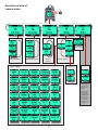
General over view of camera menu
48
View f inder display
8
Film loading
Self Timer
50
But tons and controls – details
9
Beeper26
Bracketing52
Film wind on and of f
26
Inter val54
Unloading a magazine
26
Custom Options
55
Image Info
61
Audio feedback
11
2 Camera Body
13
Carr ying strap
14
5Lenses
23
26
27
8 Custom settings
47
Tex t62
Removing & at taching the bat ter y holder 14
Par ts & Components
28
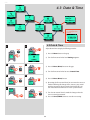
Date & Time
64
Fit ting the bat teries
14
At taching a lens
28
System status
65
Bat ter y life
14
Removing a lens
28
Digital66
Bat ter y status
15
Lens cap
28
Power15
Filter s28
On15
Lens shades
Standby15
View f inder screen
16
Accessor y connec tion
16
Shut ter and aper ture control
28
Integral f lash
69
Depth-of-f ield calculation
28
Flash measure
70
Depth-of-f ield / visual preview
29
Infrared focus set tings
29
Base plate
Focus assist
29
Manual focus
3View finder
67
General68
PC-connec tor16
16
9Flash/strobe
28
10 Optional accessories
71
30
11Appendix
76
17
Autofocus30
True E xposure
77
Par ts & Components
18
Single30
P & P v modes
78
At taching and removing the view f inder
18
Continuous31
Light metering sensitivit y
78
Eyepiece adjustment
18
True Focus
Technical specif ications
79
Eye cup
18
Default set tings
80
Integral f lash unit
18
Problems, Equipment care and ser vice
81
Quick index
82
4 Film magazine
19
31
6 Light Metering & Exposure Control 3
6
Metering method
38
Exposure method
38
Par ts & components
20
Manual exposure mode
39
LCD panel
21
Automatic exposure mode 39
LCD illumination
21
AE-L but ton
40
But tons21
Exposure compensation/Quick Adjust
42
Func tion selec tor
21
Drive43
Film plane index
21
Single43
Dark slide key
21
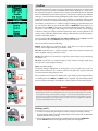
The images in this manual were not taken with a Hasselblad H4X. They are used for illustrative purposes only and are not intended to represent the image quality produced by a Hasselblad H4X. Unless otherwise stated, all images: © Jens Karlsson/Hasselblad, David Jeffery and Mats Bengtsson.
H4X
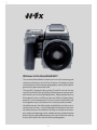
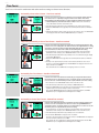
Welcome to the Hasselblad H4X!
The sensational Hasselblad H4 models are the result of unwavering and
continuous refinements to the H line of cameras. Developments have
raised the bar for medium format photography, retaining Hasselblad's
position in first place around the world.
The new H4X is designed to bring current H1 and H2 users up to a new
level of functionality. Most of the latest H4 developments are now available whether you use Hasselblad digital backs, 3rd party digital backs or
film magazines. Access to HCD lenses for use with film or 3rd party backs
and access to the revolutionary True Focus function with all backs and
film magazines are just two features in this extremely attractive model.
Hasselblad cameras, famed for quality and reliability, were chosen to record the lunar missions – there could hardly be better praise than that.
Hasselblad continues the tradition of building on well proven technologies, refining and improving to raise standards, always to produce a better
product. By using Hasselblad equipment you share the decision made by
of some of the world’s best and most famous photographers.
3
H4X
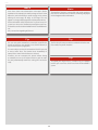
H4 features in abundance
Phocus
The H4X is a marked step up for previous H1 and H2 owners. Many
of the features from the H4 line are included, not least, True Focus.
It is a very versatile model that allows the freedom of choice between using Hasselblad CF/CFH digital backs, third party digital
backs as well as Hasselblad film magazines. The H4X is therefore
a very serious contender in the medium format world that should
appeal to a broad spectrum of photographers.
Hasselblad Phocus is the free RAW file processor to complete and
fine tune, primarily, Hasselblad raw (3FR) files from Hasselblad
digital backs. However it is capable of importing other raw formats
too, from a variety of manufacturers. You will find a copy of Phocus
on the included DVD, or you can download it directly from the
Hasselblad website.
Computer system requirements
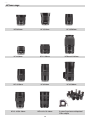
An impressive lens line
Digital files naturally end up on a computer for processing.
Image-storage and correction requires a certain minimum
standard regarding computer capabilities. Large images will require a high-performance computer with plenty of memory, advanced graphics capabilities and a recent operating system. In
most cases, the computer should include a FireWire connector,
which will enable you to load images directly from the camera.
To load images stored on the removable compact-flash card,
you could instead use a compact-flash card reader, but FireWire
is recommended for maximum flexibility.
The highly renowned HC/HCD lens line includes 11 Auto-Focus
lenses. The range is from 28mm to 300mm, 50-110mm zoom, 3590mm zoom and 1.7x converter. They all employ central shutters,
allowing flash to be employed at shutter speeds up to 1/500s. The
central shutter also improves image quality by reducing camera
vibration. And thanks to the large format of the H System cameras,
there is a considerably shallower depth of field range, making it
much easier to utilize selective focus to creative effect. In this way
the full HC/HCD lens program is even further enhanced, bringing
a new level of sharpness and resolution. (See under 'Lenses' for details about potential limitations concerning HCD lenses in combination with some digital/film backs).
Warnings and restrictions
Keep the H4X and computer equipment away from moisture wherever possible. If your camera becomes wet, disconnect from power and allow it to dry before attempting to operate again.
True Focus
True Focus helps solve one of the most lingering challenges that
faces serious photographers today: true, accurate focusing throughout the image field. The traditional solution for most DSLRs has been
to equip the camera with a multi-point AF sensor but it only resolves
some issues. To overcome this problem, Hasselblad has used modern
yaw rate sensor technology to measure angular velocity in an innovative way. The result is the new Absolute Position Lock (APL) processor, which forms the foundation of Hasselblad’s True Focus feature.
Always take great care when you remove a digital back
for cleaning as the exposed CCD sensor protective filter is
vulnerable to damage.
Keep all cables connected to or from your camera and
computer out of the way where they will not be tripped
over.
DAC (for CF/CFH users only)
Please keep purchase details and the warranty in a safe
place.
Available with Hasselblad CF/CFH digital back use exclusively,
'Digital Auto Correction' (DAC), is an APO-chromatic correction
of the images based on a combination of the various parameters
concerning each specific lens for each specific shot, ensuring that
each image represents the best that your equipment can produce.
Familiarise yourself with the various parts and components. Leave protective covers on as much as possible
and avoid touching glass surfaces and inserting fingers
into the camera body. Hasselblad cameras have a robust construction and are capable of withstanding fairly
rough treatment but nevertheless are precision instruments and will serve you longer if treated with respect
from the beginning.
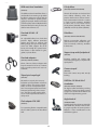
Optional Accessories
H system accessories include general items such as filters, straps
and lens shades etc., as well as specialist items such as the HTS 1.5
and the CF Adapter to really broaden your range. The HTS 1.5 tilt/
shift adapter (optional accessory) delivers an easy to use, portable
tilt/shift solution for five HC/HCD lenses ranging from 28mm to
100mm. The CF a dapter (optional accessory) allows use of the classic CF-lenses from the Hasselblad V System. Have a look at the list
towards the end of this manual for more details.
Finally, please check occasionally on the Hasselblad
website – www.hasselblad.com – for any firmware and
software updates, news, tips, user manuals or other information.
4
H4X
1
General overview
– controls
This section provides an introduction to the control buttons'
functions as well as the information provided on the display
screens.
Photo: Claudio Napolitan / Hasselblad Masters
5
H4X
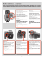
Button functions − overview
Below is an overview of the primary functions of the control wheels and buttons. Some controls have dual or triple
functions according to the state of the menu or setting. A full description can be found further on in this manual.
Shutter release button
MENU button
Releases shutter. Also activates came
ra from standby mode.
Accesses menu.
FLASH / (CONTROL LOCK) button
Illuminates grip display. Accesses
battery status and general informa
tion screen.
Locks settings to avoid inadvertent
change. Also accesses flash settings
as well as acting as Exit button.
AF button
Accesses focus modes.
DRIVE button
Accesses ISO and White Balance
settings. Also acts as Save button.
Front control wheel
Illumination/Battery status button
ON.OFF (PROFILES/ESC) button
Turns the camera on and off. Accesses
Profiles and acts as escape button for
other functions.
Rear control wheel
Accesses and changes various set
tings.
Accesses and changes various set
tings.
M.UP button
True Focus button
Eyesight correction adjustment wheel
Raises and lowers mirror. Can be
reassigned to another function.
Activates True Focus function. Can
be reassigned to another function.
Adjusts viewfinder image to suit
individual eyesight.
Remote release cord port
Format button
EV correction adjustment button
For attaching a remote release
cord (electrical).
Re-formats CF card.
Produces EV exposure compensation.
STOP DOWN button
AE-L button
EXP button
Locks light reading made in both
automatic and manual exposure
modes. Can be reassigned to
another function.
Accesses exposure mode and meter
ing method.
Stops down aperture to current
setting. Can be reassigned to
another function.
6
H4X
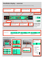
Grip display − overview
Example of typical camera grip display
Flash condition indication
(No exposure compensation,
normal flash synchronisation)
Focus setting
(Autofocus setting,
single shot mode)
Drive condition
(Single setting)
Aperture setting
(f/5.6)
Shutter speed setting
(1/400s)
Exposure Value display
(EV 13.8)
ISO setting
(100 ISO)
Low battery symbol
Exposure mode indication
(Aperture priority setting)
Metering method
indication
(Centre weighted)
White balance
(Daylight)
Capture counter
(28 shots remaining on chosen
storage medium)
Command indication
The upper row on the screens describes commands (which
change according to the setting). The button immediately above
each command effects the change. So in this case, for example,
you would press the FLASH button to ‘exit’ from the screen.
See note below.
Settings symbols
Symbolize the options available when settings are changed.
The active symbol is depicted by a drop shadow.
Control wheel description and direction
Arrowheads symbolize which control wheel should be used to
change the setting they are beside. In this case, the Bracketing
option is chosen by the front control wheel and the number of
captures in that option is chosen by the rear control wheel.
... = front control wheel
= rear control wheel
Setting information
The lower row on the screen displays information about the
current state of the setting. In short, the upper row displays
what you can do, and the lower row displays the current state of
settings or what you have done.
Typical camera grip display when changing
settings.
7
H4X
Viewfinder display − overview
Typical viewfinder display. Note the LEDs will only be visible when activated (by the camera or a setting).
Exposure method indication
(‘aperture priority’ mode)
Aperture setting
(f/5.6)
Exposure compensation
setting reminder symbol
Metering method setting
(Centre weighted)
Focus Assist LED
Flash LED
Warning triangle
LED
Exposure compensation
setting (+0.7 EV)
Shutter speed setting
(1/30 second)
Capture
counter
True Focus and HCD crop
icons appear on right
hand side of display
when functions are
activated.
Some examples of various viewfinder displays
Standard settings
Normal screen with True Focus
activated.
Normal screen with AE lock
activated.
Normal screen with exposure
compensation set.
Viewfinder display according to setting
Flash mode
Drive mode
Exposure method and
metering method mode
examples
Menu mode
etc. where:
AF mode
A = Aperture priority
S = Shutter priority
P = Program
Pv = Program (variable)
M = Manual
Exposure compensation
mode
Centre Weighted =
CentreSpot =
Spot =
8
H4X
Buttons and controls − details
A
Shutter release button
A
This button has half-press and full-press positions. By pressing half-way (or softly) the
camera, auto focus function and exposure meter can be activated. By pressing all the
way down (or more firmly) the shutter will be released (or the chosen exposure proce
dure for example, the self timer is activated with this button).
FLASH / (CONTROL LOCK) button / (EXIT)
B
This is a triple function button. If you press the button for one second, the beeper will
sound (if set) and a key symbol will appear on the grip display signifying that the con
trols (except the shutter release) have been locked and therefore cannot be altered unin
tentionally in use. Press the button for one second again to unlock (this function can be
altered to lock all controls or control wheels only in Custom Options #18).
Quickly clicking the button will access the flash settings information on the display from
the main screen. See under Flash /Strobe - controls and displays for full details.
BC DE
This button also acts as the EXIT button for many other settings including an EXIT but
ton when navigating the digital back menu.
AF button / (ON) / (SEL.)C
This is a triple function button. Press this button to directly access the autofocus/manual
focus choice screen from the main screen. See under Lenses for full details. It also acts as
the ON and SEL. (= select) buttons for many other settings.
Drive button / (SAVE) / (ENTER)D
This is a triple function button. It provides direct access to the Drive settings (see under
Lenses > Drive for full details).
It also acts as the SAVE and ENTER buttons for many other settings as well as an OK
button when navigating the digital back menu.
F
G
H
Front control wheel
E
The front and rear control wheels are used to make changes in exposure settings, access
the grip menu for settings as well as navigate the digital back’s menu. The effect of the
wheels’ direction is customizable.
MENU button
F
Accesses the first level of the menu for settings changes.
Illumination/Battery status button
G
Press to illuminate the display. Remains active until camera enters standby mode. Hold
down to access battery status/general information screen.
ON.OFF (PROFILES/ESC) button
I
H
Press the button for 1 second to activate the camera. The H4X start-up logo will appear
and then the main screen. After a few seconds (customizable) the camera will enter
Standby mode.
A long press of the button will turn the camera off completely (even from Standby
mode) signified by an audible signal (if set). A quick ‘click’ on the button will access the
Profiles section of the menu from the main screen.
Note the difference in results between a long press and a quick click of this button.
9
H4X
Rear control wheel
I
The front and rear control wheels are used to make changes in exposure settings, access
the various loop sections of the menu for settings as well as navigate the digital back’s
menu. The effect of the wheels’ direction is customizable.
J
On the rear of the grip, as well as the rear control wheel, there are a further
three control buttons:
K
True Focus
J
Activates the True Focus setting. See under Lenses / True Focus for explanation of this
function.
L
Format button
K
Re-formats a CF card. Purposefully recessed to prevent unintentional use. Dialogue
appears for confirmation.
AE-L button
Note
Reassignable buttons are parti
cularly useful and can save you a
great deal of time and effort. You are
advised to investigate their potential
fully. See Custom Options for full
details.
L
This button can lock a light reading made in both automatic and manual exposure
modes. It can also be used in Zone mode to take a new reading.
Can be reassigned in Custom Options to another function.
See under Light Metering & Exposure Control / AE-L button for full details.
On the front of the grip there are two more control buttons plus the remote
cord release port:
M.UP button M
Press this button to raise the mirror and press again to lower it (toggle function). A quick
double press of the button (two within a half second) will immediately access the Self
timer function.
Can be reassigned in Custom Options to another function.
M
N
O
Remote release cord port
N
For attaching a remote release cord (electrical). The Hasselblad accessory jack plug
socket is protected by a captive rubber plug.
STOP DOWN button
O
Press this button to make a visual check of the depth-of-field on the viewfinder screen at
the chosen aperture. The aperture will close according to the setting and remain closed
as long as the pressure is maintained. You can alter the aperture at the same time to see
the changes taking place.
Can be reassigned in Custom Options to another function.
10
H4X
There are also two control buttons on the viewfinder, as well as the eyesight
correction adjustment wheel:
Eyesight correction adjustment wheel P
The personal eyesight adjustment facility has a diopter range of -5 to +3.5, to suit most
users.
ON:
EV correction adjustment button Q
Press this button to access the EV compensation screen. Settings are made with either
the front or rear control wheels. An EV correction symbol appearsOFF:
on the grip and view
finder display as confirmation.
EXP button P
Q R
Error:
R
The EXP (Exposure) button accesses the exposure mode and metering method options
screen. Settings are made with the front and rear control wheels and the appropriate
Ready:
symbols appear on the grip and viewfinder displays accordingly.
Low battery:
ON:
Overexposure:
OFF:
Underexposure:
Error:
5 images left:
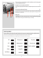
Audio feedback
There are 14 different sounds to help provide immediate information.Ready:
A button press has a normal mechanical ‘click’ sound while the remain1 image left:
ing actions listed here are more musical. For example, a capture rated as overexposed is signified by three rapid notes going up the musical
scale, whereas an underexposed capture has three rapid notes going down the musical scale, as illustrated here.
See later section about available options on the digital capture
unitbattery:
for activation and volume control.
Low
Media full:
ON:ON:
Overexposure:
Overexposure:
IAA
yellow:
IAA
yellow:
OFF:
OFF:
Underexposure:
Underexposure:
Overwrite
red:
Overwrite
red:
Error:
Error:
5 images
left:
5 images
left:
Transfer
complete:
Transfer
complete:
Ready:
Ready:
1 image
left:
1 image
left:
LowLow
Battery:
battery:
Media
Media
full:full:
Overexposure:
IAA yellow:
11
H4X
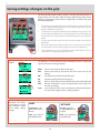
Saving settings changes on the grip
The basic principle behind making changes is that the appropriate button is
first pressed to access the menu and then settings altered by way of the control
wheels. The appropriate control wheel is designated by arrowheads alongside
the setting description.
·Some buttons have a toggle function, the ON.OFF button has a quick ‘click’ a ction
·
·
·
·
·
Examples
as well as a longer (half-second) ‘press’ action and the shutter release has two
positions: ‘half-press’ and ‘full-press’.
Several buttons on the grip are multifunctional, according to the state of the menu.
In the example illustrated here, the FLASH button functions as the EXIT button, the
AF button functions as the ON button and the DRIVE button functions as the SAVE
button.
The front and rear control wheels can also be used to navigate the menu on the
digital back.
At very low temperatures the displays require a few seconds to present new settings.
The control wheels are also used to navigate the menu on the digital back.
The FLASH button also acts as an EXIT button and the DRIVE button acts as an
OK button when navigating the digital back menu.
The following is a list of the various terms describing the various actions that
appear in the menu (on the grip display):
Enter:
Exit:
Off:
On:
Sel.:
ESC:
Save:
Remember the follow
ing groupings of ‘saved’
and ‘not-saved’ actions
when making settings
changes:
moves screen down one level on the menu.
moves screen back up one level on the menu. Does not save any
settings.
deactivates the particular function being set.
activates the particular function being set.
(Select) - selects the character marked for image info and profile name
(Escape) - terminates an action and returns to the main screen. Does
not save any settings.
saves a setting and also moves screen back up one level on the menu.
Can save many changes made in a setting sequence.
SAVED
NOT SAVED
‘Quick save’ - halfpress shutter release
button
Escape - press ESC
button (PROFILES /ESC
button)
Save - press save but
ton (DRIVE button)
Exit - press exit button
(FLASH button)
12
H4X
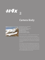
2
Camera Body
Aluminium cast in one piece
Stainless steel shell
Integral quick-coupling plate
Upgradeable firmware
Modular design
Integral ergonomic grip
Pixel based user interface
Photo: Bang Peng / Hasselblad Masters
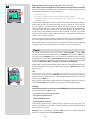
The H4X camera body is a robust construction of cast alu
minium with a stainless steel shell for extreme durability.
The integral ergonomic grip houses the main control interface
and also contains the battery holder. The camera body also
contains the viewfinder screen, which can be easily removed
or exchanged without the use of special tools or adjustment
procedures.
Please take extra care when handling the camera body with
out a protective cover or the digital back in place to pro
tect the auxiliary shutter. Likewise, the front opening of the
camera body reveals the mirror when unprotected by a cover
or lens. Do not touch or attempt to clean the mirror yourself
– marks or dust particles will not impair results in any case.
More noticeable problems, however, should be taken care of
by a Hasselblad Authorized Service Center.
13
H4X
1
Carrying strap
2
1, 2
The carrying strap is attached by firstly withdrawing the safety
collar. The hook is then freed and attached to the strap lug (fig. 1).
Slide back the safety collar (fig. 2) to ensure the hook remains in
the locked position between the small protruding lugs. The collar
is purposely a tight fit and might need some effort to slide.
Removing and attaching the battery holder
3
The H4X requires batteries for all actions. There is no mechanical
reserve facility so it advisable to always have a spare set of batter
ies. As is normal, you might want to keep a reserve set of batteries
in a warm place when working in very cold conditions.
4
Remove the battery holder by depressing the the battery holder
button (A) and simultaneously swinging the battery holder re
taining lever (B) down until it stops. Pull battery holder down
wards (C).
A
C
To attach ensure the battery holder is flat against the camera grip
and, aligning the two upper lugs with the slot in the grip, slide
it back into position as far as it will go. Swing back the battery
holder retaining lever until it clicks back into place.
B
5
3
Fitting the batteries 6
4, 5, 6
With the battery holder removed, press the red battery cassette
retaining button inwards on the holder to release the battery cas
sette . Load three CR-123 lithium (or equivalent) into the cassette,
ensuring the polarity of each battery is correctly oriented (see the
‘+’ markings on the batteries and the cassette). Re-insert the cas
sette into the battery holder, ensuring that it is seated properly in
place and that the red button returns fully into the locked posi
tion.
7
Battery life
8
7, 8
Battery life is dependent on a number of variable factors and
therefore cannot be exactly predicted.If the camera is left in the
active state instead of standby for long periods, for example, then
the battery will become exhausted much faster. A low-battery
state is indicated as a symbol on the grip LCD (fig. 7).
When the batteries are almost completely exhausted, a warning
message ‘Replace battery’ will appear on the grip LCD (fig. 8). The
camera will not function at all when this message appears and
battery change is essential.
Note
When the Low battery icon appears (as in illus 7), the camera automatically enters a temporary p ower-saving mode. This is recognizable by a slower pace for all the actions in a capture sequence.
The camera actions also sound differently.
This mode is designed so that you can continue working for a
while, even though the power remaining in the battery is too low
for working in the normal manner. Naturally, you should replace
the battery as soon as possible to restore normal action again.
14
H4X
9
Battery status (Battery grip rechargeable 7.2V Li-on only) 9
With a 'Battery grip rechargeable 7.2V Li-on' (optional accessory) fitted an immediate
full-screen information and battery status check appears on the grip display by holding
down the illumination button. This screen displays:
• the firmware version
• the number of captures taken since the last battery recharge / change.
• a rechargeable-battery status icon that provides a quick visual check as well as a figure
estimate in percent.
The information regarding the number of captures taken is intended to help you make an
estimate of the number of possible remaining captures according to your way of work
ing. For example, if you regularly browse a great deal when shooting or you leave the
camera in ON-mode with no standby, you would naturally expect to drain the battery
sooner than others who don’t. You should soon be able to build up a picture of how you
usually work and can therefore estimate that after X number of captures, you normally
expect to be able to take Y captures before the battery is exhausted (when working in a
similar manner in similar conditions).
The percentage information, however, provides another kind of estimate based more on
the amount of power left in the battery rather than on your normal way of working.
Remember that these are only estimates and that there are a number of factors affecting
remaining battery, ambient temperature for example, as well as general practice.
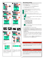
Power
The camera can be set at two active power modes − ON or Standby − as well as OFF.
In active modes, battery consumption is least in Standby mode and most in ON mode.
The camera enters Standby mode to conserve battery consumption after 10 seconds
(Default) but can be changed in Custom Options #1. Both the grip and the digital back
displays are dimmed accordingly. The digital back can be set to become independently
inactive in Power Down (Menu > Settings > User Interface > Power Down).
Note that after 1 hour of complete digital back inactivity in power down mode, the camera
body will automatically shut down too. Restart by pressing the ON.OFF button on the
grip as normal.
ON
To activate the camera press the red ON.OFF button until you see the start-up H4X logo
appear on the grip display. The logo is automatically followed by the main screen. The
camera is now in ON mode.
After a set period of inactivity (programmable in Custom Options) the camera automati
cally enters Standby mode, signalled by the appearance of the H4X logo again.
Standby
In this mode the camera is in a mainly inactive Standby mode and is ready to be imme
diately reactivated to the ON mode by:
• pressing the shutter release button half way
• pressing the Stop down button
• clicking the ON.OFF button
• pressing the Mirror up button.
In this mode, signalled by the standby H4X logo appearing on the grip display, the
demand on the batteries is very low. It is ideal for general use where intervals between
shots exceed a few seconds.
Standby mode is automatically set from the ON mode after 10 seconds (default) of
inactive use (programmable in Custom Options #1).
15
H4X
16
OFF
17
From the active screen, press (not click !) the red ON.OFF button
for a half second. All buttons (except the ON.OFF button) remain
ineffective, producing virtually no demand on the battery. This
is the normal mode when transporting or storing the camera
or where there might be a risk of inadvertently activating the
camera. (However, remove the batteries if you are going to store
the camera for a period of more than a few weeks).
In this mode neither the viewfinder display nor grip display infor
mation is available.
Viewfinder screen
16, 17
The H4X is fitted with a Spherical Acute-Matte D viewfinder screen
for extreme brightness, clarity and even illumination. An optional
accessory screen with a grid pattern is also available.
To change a viewfinder screen, remove the viewfinder to access
the viewfinder screen. To remove the screen, place the tip of a
ballpoint pen or similar in the viewfinder screen removal lug and
pull upwards. To replace the screen, position the right side of the
screen in place so that it sits correctly in the recess. Place the tip
of a ballpoint pen or similar in the viewfinder screen replacement
indentation and press downwards until the screen snaps into
position. Try to avoid touching either surface of the screen with
bare fingers.
Viewfinder screens showing the difference in masking and
composition frame marking. Type varies to match sensor size.
See under Accessories for other types (with grid pattern, for
example).
Note
18
Do not attempt to clean the screen by immersing it in water, or use
any kind of cleaning fluid. If the screen becomes damp, do not use
hot air to dry it. Use a soft cloth on the upper surface only. Seek
advice from an Authorized Hasselblad Service Center if the screen
becomes particularly soiled. Remember that particles or greasy
marks on the screen might impair the viewfinder image but have
no effect whatsoever on the recorded image
19
Accessory connection
20
18, 19
On the left hand side of the camera body are two accessory-
retaining screw threads (M5), as well as a databus connector,
protected beneath a cover.
The cover can be removed by inserting a pointed object, such
as a pen, in the small hole and then sliding it to the left, as in the
illustration. The cover-retaining clip can then also be removed to
access the connector.
21
PC-connector20
22
A PC connector for non TTL-flash synchronisation is located on
the left side of the body. It is protected by a captive rubber plug.
Protective base plate
21, 22
To attach the protective base plate, slip it over the camera foot
until it stops. To remove it, lift the securing catch while pushing
the plate back towards the lens.
16
H4X
3
Viewfinder
Multi-mode light metering
Full exposure information
100% image
90° viewing angle for eye-line composition
Full image for spectacle wearers
Integral diopter adjustment
Integral flash unit
Photo: Joao Carlos / Hasselblad Masters
The viewfinder provides a laterally corrected 100% image at
eye-line level. It features a wide-range diopter adjustment to
suit most users. The viewing distance is designed to provide
full frame view even for eyeglass wearers. The bright Spherical
Acute-Matte D focusing screens (located in the camera body)
are interchangeable to suit preference, each of them naturally
indicating the spot light-metering area for accuracy in expo
sure calculation. The information display located beneath the
viewing frame is continually updated and visible and is back
lit for optimum visibility. This display also duplicates much
information visible on the grip display for immediate check
ing. In addition to the display, there are four LEDs providing
general warnings, flash and focus information. The viewfinder
also features a pop-up fill-flash unit for added convenience.
See the Camera Body section for details about the view
finder screen. The exposure compensation button and expo
sure button are described in the Light Metering & Exposure
Control section.
17
H4X
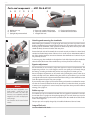
Parts and components – HVD 90x & HV 90 A
B
C
D
A. Rubber eye cup
B. Hot shoe
C. Eyesight adjustment wheel
E
F
G
D. Exposure compensation button
E. Exposure method / mode button
F. Integral flash unit
H
G. Flash unit release button
H. Viewfinder release button
Attaching and removing the viewfinder
1
1
2
1
While holding the viewfinder at a slight angle and resting it on the top of the camera,
slide the viewfinder forward until the front locating pin is in position in the recess in the
front edge of the viewfinder screen aperture on camera body. Press the rear part of the
viewfinder firmly downwards until it clicks into place.
Ensure that both sides of the viewfinder are seated correctly and that it has been firmly
attached and locked into position. Failure to do so could cause an intermittent malfunc
tion if the databus interface connections between the viewfinder and camera body are
not positively secured.
To remove, grasp the viewfinder in the right hand and while depressing the viewfinder
release button, lift the rear of the viewfinder up and away from the camera body.
Eyepiece adjustment
2
2
No corrective lenses are needed to adjust the eyepiece to suit most requirements. The
diopter range is from -5 to +3.5D. Eyeglass wearers can rapidly and accurately change
the settings according to whether they wish to wear eyeglasses for viewing or not.
Personal eyepiece adjustments can be carried out by pointing the camera at the sky or
similar smoothly toned area. While holding the camera in your left hand, you can with
your right thumb turn the adjustment wheel until the markings on the viewfinder screen
reach the optimum sharpness for your eyesight.
Note
There are three compatible viewfinder models – HVD 90x, HV 90x
and the HV 90X-II The HVD 90x,
however, is not compatible with film
magazines as it does not display the
whole image.
User functions are the same for both
models.
If you normally wear eyeglasses for distance viewing and intend to wear them for camera
use then do not remove them for the above procedure. If, on the other hand, you prefer
to remove your eyeglasses for camera work, then repeat the above procedure without
wearing your eyeglasses.
Rubber eye cup
Two rubber eye cups are available for the H4X. The one supplied is suitable for users who
do not intend to use eyeglasses when photographing. The second shorter eye cup is for
those who either prefer to position their eye further from the viewfinder and those who
wish to wear eyeglasses.
The eye cups can be rapidly changed by a Hasselblad Authorized Service Center.
Integral flash unit
See under Flash for full details.
18
H4X
4
Film Magazine
The 16-32 film magazines are sophisticated independent
units within the H system. They allow the use of 120 or 220
film. Features include automatic film advance, wind on and
wind off. A display provides information while some settings
data can be printed on the edge of the film for archival pur
poses.
Film magazines not only provide for special requirements in
technical applications but also allow a broader spectrum of
expression for creative work.
Photo: Mark Zibert / Hasselblad Masters
19
H4X
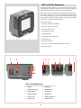
HM 16-32 Film Magazine
The HM 16-32 film magazine is a sophisticated semi-independent
unit within the modular H-system. It has its own power supply for
individual information storage, LCD panel, illumination, etc.
Much information is transmitted and received between the maga
zine and the camera body, so ensure the databus connection is kept
clean and not damaged in any way. It is advisable to fit the maga
zine protective cover when storing a film magazine to protect both
the databus connection and the darkslide.
The features include:
• Automatic 120/220 compatibility
• Automatic wind on / wind off
• Automatic film advance
• LCD information panel
• Integral darkslide
• Customizable data imprinting
• Illuminated LCD
• Barcode recognition
• Count-up or count-down film frame reminder choice
• Multi shot option
A
F G H
B
I
C
D
E
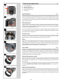
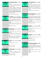
Parts and components
A.
LCD panel G.
B.
LCD illumination button H. Darkslide indicator
C.
Change up button I.
Film tab holder
D.
Change down button J.
Film holder key
E.
Function selector K.
Magazine settings lock
F.
Film plane index
L. Databus interface
20
Darkslide key
J
K
L
H4X
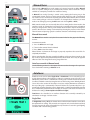
LCD panel
A
B
A
The various functions are accessed by repeatedly pressing the
function selector button (loop menu) and changes made by the
‘change-up’ and ‘change-down’ buttons. Any settings are auto
matically saved. At very low temperatures the LCD will require a
few seconds to display new settings.
LCD illumination button
C
D
B
The LCD can be illuminated by pressing the display illumination
button, which is accessible when the magazine is not attached to
the camera. The LCD will remain illuminated all the time you keep
the button depressed, up to a maximum of 10 seconds. After 10
seconds has expired, you must release the pressure on the button
and press again to obtain a further 10 second period of illumina
tion. Remember that using the illumination function very often
will noticeably shorten the life of the battery in the magazine.
When the magazine is attached to the camera, the button on the
magazine is inaccessible but you can still illuminate the LCD by
pressing the illumination button on the grip instead.
Change up button F
E
C
Can change the settings ‘upwards’. For example, to increase the
film speed setting. Toggle action.
Change down button D
Can change the settings ‘downwards’. For example, to decrease
the film speed setting. Toggle action.
Function selector
G
H
E
Selects the four functions that can be set on the magazine. The
functions are on a menu loop so that repeated pressing of the se
lector button will successively access all functions in turn. After a
time-out of five seconds of non-activity, the display returns to the
main screen.
Film plane index
F
Provides a measuring point for the actual position of the film plane
in the magazine. Used for calculations in critical applications.
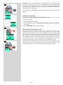
Darkslide key
G
Withdraws and replaces the darkslide. Fold out the key and turn it
counter-clockwise 360° (towards the open symbol) to withdraw
it and clockwise 360° (towards the closed symbol) to replace it.
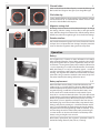
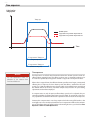
Darkslide indicator
Note
Changes can only be made when the settings lock switch is in
the unlocked position.
Note
The darkslide can only be withdrawn when the magazine is
attached to the camera. H
Indicates whether the darkslide is in place or withdrawn:
RED
=
WHITE =
stop ! =exposure CANNOT be made (magazine can be removed from camera)
ok ! = exposure CAN be made
(magazine cannot be removed from camera)
If you attempt to make an exposure when the darkslide is closed,
however, you will receive a warning message in the viewfinder and
grip LCDs – ‘The darkslide is closed’.
21
H4X
I
J
Film tab holder
I
Holds an ID tab from the film roll pack as a reminder of the type of
film loaded. Don’t forget to change it if you change film type!
Film holder key
J
Secures the film holder in the magazine. Fold out the key and turn
counter-clockwise 90° to remove the film holder and turn clock
wise 90˚ to lock the film holder in place.
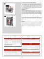
Magazine settings lock
K
L
K
All settings can be locked to avoid inadvertent changes. To change
the settings, slide the settings lock (see illus) to the right until it
stops. After the changes have been made, slide the settings lock to
the left (see symbol on magazine) again to secure the new settings.
Databus interface
L
Data interface between magazine and camera. Ensure the contacts
are kept clean and protected from damage. Keep the protective
cover on when the magazine is being stored or transported.
Operation
1
Battery
The magazine uses a battery to retain information and settings
when unattached from the camera. When attached to the camera
body, the magazine takes its power requirements from the cam
era batteries. The magazine battery will normally be effective for
1-2 years depending on use (off camera illumination, for example).
When the battery is in a very low condition, (approx. 1 month of
use left), a low-battery symbol appears on the magazine LCD as a
warning. The magazine will continue to function with no battery
power left as long as it remains attached to the camera body. How
ever, when detached, the settings will not be stored.
Battery replacement
2
1, 2
Release the film holder by folding out the film holder key and
rotating it 90° in a counter-clockwise direction. Withdraw the film
holder completely. On the bottom plate on the inside of the film
magazine housing you will find a slotted circular battery cover.
Insert a small coin or similar into the slot and rotate the cover
about 20° in a counter-clockwise direction. The cover will be freed
and the battery can be removed. Replace with a fresh CR2032 / 3V
lithium (or equivalent) battery. Observe the polarity and ensure
the positive (+) face is uppermost and replace the cover (ensure
the retaining lugs are inserted in the battery compartment slots),
locking it into place by rotating it in a clockwise direction until it
stops. If you inadvertently insert the battery incorrectly, the film
magazine will not be damaged though it will not function. Try to
avoid touching the surface of the battery with your bare fingers
as sweat residue can decrease the electrical conductivity of the
battery casing and might cause corrosion.
After battery replacement, the magazine’s parameters return to
the default settings (Barcode, 120, Data-on, Count up).
22
H4X
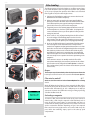
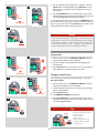
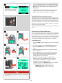
Attaching and removing the magazine
3
3, 4
You cannot remove a magazine from the camera body if the mag
azine darkslide is not in place, (when the magazine darkslide in
dicator on the magazine shows white). Neither can you withdraw
the magazine darkslide when the magazine is not attached to the
camera. Both these restrictions therefore prevent accidental film
loss caused by fogging.
Attachment
Position the magazine retention groove onto the magazine sup
port on the camera body ensuring that they are correctly posi
tioned. Swing the magazine towards the camera body and firmly
press into place with a click. If there is resistance, the magazine
retaining catch on the camera has probably been inadvertently
released. In that case, push the release button again to reset the
catch.
4
You can attach and remove the magazine with or without the film
holder in place. If you just want to change to a new film, you can
remove and reload the film holder without having to remove the
whole magazine.
1
Removal
Ensure that the darkslide indicator on the magazine shows red (sig
nifying that the darkslide is closed). Firstly push the lever of the
magazine release button to the right (fig. 4/1) and while maintain
ing that position press the centre of the button firmly inwards to
wards the camera body (fig. 4/2) to finally release the magazine.
2
Note
Note
If the film holder is inadvertently removed mid-film, then
exposed frames will naturally be lost due to light fogging.
However, if the film holder is re-inserted, the film will automatically be advanced by three frames to position fresh
unexposed film. The film counter will also correspondingly
add on three frames to the original number recorded before
the film holder was removed. You cannot remove a magazine if the darkslide is not closed. Note
Film settings (ISO / film length) are automatic only if the
magazine is set at Barcode automatic. That is, a barcoded
film cannot override a manual film speed setting but a manual setting can override the film speed of a barcoded film.
Note
Films without a barcode must have their speed set manually. A manual setting must also be made if you want to
override the speed setting of a barcoded film.
Note
Ensure you press on the centre of the button, not on the lever.
23
H4X
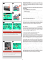
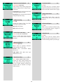
Magazine settings
Press the function selector (
access:
button ) repeatedly to successively
A. Film speed (ISO / Bar Code)
C
A
B. Film length (120/220/ Number of frames)
C. Data (on/off)
B
D
E
1
3
E. Low-battery warning symbol
Film speed setting / barcode
The film speed (ISO / ASA) can be set automatically or manually.
Automatic setting uses a barcode (only some films have this fea
ture, notably Fujifilm). This is the default setting.
2
4
D. Frame counter (count down / count up)
To access Manual setting:
EXAMPLE
1) Ensure the magazine settings lock is in the unlocked position.
2) Press the button until a figure (or barcode symbol) appears
together with ISO.
3) Press either the or the button to reach the required setting.
4) The new setting will be saved automatically after a time out of
five seconds.
5) Return the LCD settings lock to the locked position.
Film length/number of frames
Both 120 and 220 films can be used. 120 film will produce 8 (for
use with ‘half-length’ 120 films only) or 16 frames and 220 film will
produce 32 frames.
If the film has a barcode, then film length setting (and film speed
setting) is automatic. The LCD will automatically show the barcode
symbol and the appropriate film length. (Note that film speed can
be overridden with barcoded films, but not film length).
5
Film speed
Film length
Data
Frame counter
If, however, the film has no barcode then proceed as follows:
To access film type setting:
1) Ensure the magazine settings lock is in the unlocked position.
2) Press the button until the 120 or 220 symbol appears.
3) Press either the or the button to change the desired
setting.
4) The new setting will be saved automatically after time-out.
5) Return the magazine settings lock to the locked position.
Data imprint setting
Data imprinting can be activated or deactivated through the mag
azine menu.
Note
If you use both standard and barcoded films (or overridden
barcoded films), check that you have changed the settings
accordingly.
To access data setting:
1)
2)
3)
4)
Ensure the magazine settings lock is in the unlocked position.
Press the button until the Data symbol appears.
Press either the or the button to reach On or Off.
The new setting will be saved automatically after a time out of
five seconds.
5) Return the magazine settings lock to the locked position.
24
H4X
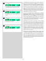
Frame counter setting
The frame counter can be set to show either how many unex
posed frames remain on a film or how many frames have already
been exposed. The LCD shows your choice of setting by adding
the word Remain as a reminder of the number of frames remaining or ‘countdown’. Absence of this word implies the opposite,
namely, ‘count-up’, so it denotes the number of the next frame
to be used (for example, the figure 4 means three frames have
already been exposed). This information is also automatically dis
played on the grip LCD and viewfinder LCD though only as a fig
ure above a symbol.
220 film length
setting.
Manual film
speed setting.
To access frame counter setting:
Data imprinting
setting.
1) Ensure the magazine settings lock is in the unlocked position.
2) Press the button until Remain appears.
3) Press either the button or the button to reach the desired
setting (toggle function).
•‘on’ will show the number of frames remaining on the roll.
•‘oFF’ will show the number of the next frame in the series.
4) The new setting will be saved automatically after a time out
of five seconds.
5) Return the magazine settings lock to the locked position.
‘Frames remaining’
counter setting.
Note
Low-battery symbol
Operation and changes made to the data imprinting function are accessed through the camera menu. Please see separate section in camera User Manual for full details.
The low-battery symbol only appears on the magazine LCD when
the battery needs changing.
Example
In the example shown here:
25
• 120 film length set manually
• the film speed (ISO160) has been set manually
• 5 frames have already been exposed (therefore with regular 120 film, 11 frames remain)
• the battery is functional
H4X
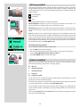
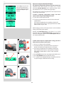
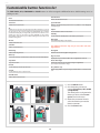
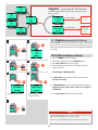
Film loading
1
2
1
2
3
4
5
1
The film magazine can be loaded either on or off the camera. Regu
larly check the interior of the magazine and remove dust, particles
or any scraps of paper from previous rolls of film. Load and unload
film magazines away from direct light sources.
1) Fold out the film holder key and turn it counter-clockwise 90°.
Withdraw the film holder completely.
2) Place an empty take-up spool in the upper spool holder by
placing one end over the fixed stud in the holder and the other
end underneath the sprung spool retaining arm. Rotate the
spool a little if necessary until it clicks into position.
3) Completely remove the retaining paper band from a new roll
of film and place it in the lower spool holder. See diagram for
correct orientation. Ensure you do not place the film spool the
wrong way around!
4) Pull 8–10 cm (3–4 in.) of paper backing from the film roll and
insert the tongue of the backing paper into the slot in the
take-up spool. Turn the spool one complete turn to ensure the
tongue is firmly held in place by the overlying paper backing.
5) Re-insert the film holder into the main body of the film magazine ensuring the correct orientation. Press firmly inwards
towards the magazine and pay particular attention to see that
both sides are level with the magazine body before turning the
film holder key clockwise 90˚ to lock the film holder in place
and fold the key back into its stored position. You might find
that increased pressure on the left hand side of the film holder
will more easily ensure a positive and correct positioning in the
magazine.
If the camera is active or in standby mode the film will be
wound automatically by the camera to position the first frame
(this function can be changed in Custom Options so that the
film is advanced only when the shutter release button is pressed
the first time).
Beeper
The beeper sounds immediately after the last-but-one frame has
been exposed. This function can be turned off in Custom Options.
2
Film wind on and off
6, 7
Wind on: See ‘Film wind-on’ under Custom Options for a setting
choice.
6
7
Wind off: When the last frame has been exposed, the film will au
tomatically be wound off. However, to wind off a film sooner, press
the film wind off button (fig. 6). Use a ballpoint pen or similar to
activate it. You must also confirm the message on the grip LCD (fig.
7) before the film winds off.
Unloading a magazine
To remove a film, remove the film holder in the same manner as
when loading a film. Grip the exposed roll of film firmly and re
move. Ensure the paper backing is wound tightly and that it is
sealed with the band properly (the band may need to be moist
ened to activate the adhesive depending on type). Store exposed
films away from strong light sources and contact with sharp ob
jects. Move the remaining empty spool to the take-up spool
compartment.
26
H4X
5
Lenses
Rapid and accurate automatic focusing capability
Central electronic shutter
Instant manual focus override with natural friction
Instant automatic-focus access in manual mode
Non-rotation of filter or accessory when focusing
Non-rotation of focus ring in automatic focusing mode
Flash sync at shutter speeds from 256s to 1/800s
Automatic detection of extension rings and converters
C type lenses from the V system can be used in combi
nation with CF Adapter (optional accessory)
All HC lenses have been specially formulated for the H system
to produce the extremely high performance expected from
Hasselblad. In addition to exceptional sharpness, the design
also incorporates a very pleasing bokeh. All lenses feature an
electronically controlled central shutter designed to extreme
ly fine tolerances for supreme accuracy. To ensure reliable and
fast autofocus in low contrast and low light conditions, an AF
focus assist light (on the grip) is automatically activated.
Photo: Stephan Zirwes / Hasselblad Masters
As a general rule, lens shades should always be fitted to
achieve optimum performance. Protective filters (UV / Sky)
should also be considered at least when working outdoors in
harsh conditions.
For CF/CFH users only, DAC lens corrections can be applied in
Phocus for outstanding results to markedly reduce chromatic
aberration, distortion and vignetting.
27
H4X
Parts and components
1
A.
B.
C.
D.
E.
A
B
C
D
E
Lens shade index
Manual focus ring
Focusing distance scales
Depth-of-field scales
Lens index
Attaching a lens
2
1
2
1
2, 3
Remove the front protective cover on the camera body by depressing the lens release
button and keeping it depressed while turning the cover counter-clockwise. Remove the
rear lens cap by unscrewing it in a counter-clockwise direction. Align the index on the
lens with the index on the camera body and rotate the lens clockwise (bayonet fitting)
until it clicks into place.
Removing a lens
Depress the lens release button and keep it depressed while rotating the lens counterclockwise until it stops and lift it out. Replace protective caps on the lens immediately
and on the camera body if necessary.
3
o
o
If you try to rotate the lens before you press the lens release button, it might lock. In this
case, rotate the lens clockwise a little first and then re-attempt removal with the correct
procedure: button first, then lens.
Front lens cap
4
Front lens caps are released for removal and attachment by inserting a thumb and index
finger into the recesses and pinching in the direction of the arrows.
Filters
Filters have a screw thread fitting (67 / 77 / 95 mm, according to lens) and are screwed
clockwise into place. As there is no rotation of the front section of the lens when focus is
changed, filters do not rotate either. This is particularly useful when using polarizing or
graduated filters where the orientation is normally critical.
4
Lens shades
5, 6
All lenses are supplied with lens shades that additionally provide extra protection for
transport and storage when mounted in reverse. Lens shades have a bayonet fitting
and are turned clockwise into place after ensuring the index on the lens shade aligns
with the index on the front of the lens. When mounted in reverse, they are attached by
matching the indexes and turning clockwise.
5
o
o
Shutter and aperture control
Both the shutter and aperture are electronically controlled and are adjusted by the
control wheels on the grip. There are no separate manual setting rings on the lenses or
camera body.
The chosen settings are displayed both on the grip display and in the viewfinder display.
See under Light Metering & Exposure Control / Exposure Method for a complete ex
planation.
6
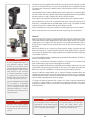
Depth-of-field calculation
7
There are two distance scales (in feet and metres) visible through the focus distance
window on the upper part of the lens barrel. There is also a central lens index mark and
a depth-of-field scale. The focusing distance is read off the chosen scale from the central
lens index.
28
H4X
Depth-of-field can be calculated as follows:
7
1. Focus the lens as required.
2. Make an exposure reading (auto or manual) and note the aperture setting.
3. Find the markings on either side of the central index that correspond to the chosen
aperture.
4. From these two markings, read off on the required lens distance scale the two
corresponding distances.
5. The depth-of-field (at that particular aperture and focus setting) will be the area
included between these two distances.
In the example given here, the focusing distance is set at nearly 3 metres. At an aperture
of f/22, the depth-of-field would therefore extend from just over 2 m to approximately
4.5 m. Note that depth of field is not an absolute. Perception of it depends on several
factors and so it should be seen only as a rough guide.
8
Stop down / depth-of-field
8
A visual depth-of-field preview can be made by depressing the STOP DOWN button
while viewing the image on the viewfinder screen.
Infrared focus settings
9
10
As infrared rays form an image at a different plane to that formed by visible light, the
normal focus settings do not apply. Proceed as follows in manual focus mode:
Lens focus setting too far
beyond the distance of the
subject framed by the central
section in the viewfinder
1. Focus the lens in the conventional manner until satisfied.
2. Note the distance setting against the central lens index.
3. Re-align this distance setting against the infrared mark (coloured red) instead of the
central lens index.
Alternatively if you have already calculated the required distance, you can make a
manual distance setting by using the distance scales together with the infrared mark
instead of the central lens index.
For specialists, please contact your Hasselblad dealer for information about digital backs
adapted solely for infrared photography.
Focus assist 11
9
Focus setting too close for the
distance of the subject framed
by the central section in the
viewfinder
10, 11, 12
As well as the conventional view on the focusing screen to ensure a sharp image, the H4X
also features an LED focus assist capability appearing as two arrowheads to the right of
the viewfinder display (except for lenses with a maximum aperture of f/6.7 or smaller).
The arrowheads provide confirmation of a precision focus setting and are a useful aid
when making a setting with eyesight alone.
Manual focus setting
12
Focus setting correct
When the left arrowhead alone appears it means the focus setting is too far beyond
the chosen distance (the area framed within the central zone in the viewfinder) and
when the right arrowhead alone appears it means the focus setting is too close. Focus is
correct when both arrowheads appear together. If the focus cannot be established, then
both arrowheads flash.
Automatic focus setting
Focus is correct when both arrowheads are visible together. Focus is incorrect if only
one arrowhead is visible. If the focus cannot be established, then both arrowheads flash.
29
H4X
Manual focus
1
There is both a Manual focus mode setting and a manual override capability. Manual
focus is a specific setting that you actively make, whereas manual override is always
available as a temporary override of an autofocus setting.
AF
In Manual focus mode, focusing is carried out by rotating the focusing ring in the
conventional manner. The focus setting remains until changed as with a conventional
non-autofocus lens. This means that pressing the shutter release button will not activate
a focus setting change as it does in autofocus. To change back to autofocus, you must
make a new setting (by pressing the AF button and choosing AF S or AF C).
With manual override you can manually alter a focus setting that has been made in the
autofocus mode, by rotating the lens barrel in the conventional manner and without
having to change modes. As long as the shutter release button is kept at the half-press
position, the new focus setting is maintained. By releasing the pressure on the shutter
release button and pressing again, the autofocus function is immediately reactivated.
2
F
Manual focus mode
The Manual focus mode is set by the front control wheel on the grip in the following
manner:
In camera active mode:
3
DRIVE
Save
1) Press the AF button on the grip.
2) Turn the front control wheel to: Manual
3) Press Save to store the setting.
Natural friction is inherent in the design to purposely reproduce the secure feel of a
completely manual lens.
Please note that when focusing manually, the infinity and closest distance marks on the
lens scale can appear to be positioned beyond the central index. This is only an apparent
effect and does not change the focusing range of the lens.
Autofocus override in Manual mode
See the following section for a description of how to use the advantages of a rapid auto
focus check while remaining in Manual mode.
Autofocus
4
Autofocus mode can be either Single Shot or Continuous and is activated by press
ing the shutter release to the half-press position. Its operative range is from EV1–19 at
ISO100. The point of focus is determined according to the vertical and horizontal areas
(see illus 4.) within the central rectangular zone on the focusing screen. When light levels
are too low or the contrast of the subject is too low, auxiliary illumination (situated on
the top of the grip) is automatically activated if desired. The operative distance is ap
proximately six metres from the camera. Alternatively, a suitable attached flash unit that
has a similar facility (a Metz 54/70, for example) can also be used instead. This feature can
be altered in settings (Custom options #16/AF assist light).
True Focus is also classified as an autofocus function and is normally activated by its
own button on the grip. See later section.
Single Shot
At Single Shot setting (AF S), the shutter release will be blocked until the camera finds
the optimum focus setting. This ensures that no captures can be made that are not finely
focused. However, this delay will normally be only a fraction of a second in good lighting
conditions with a clear focusing pattern.
30
H4X
Note though that in this mode the lens will focus at a distance and will remain focused
at that distance while pressure remains on the shutter release button. In this way, you
can focus on a nearby object for example, temporarily positioned within the focusing
zone on the viewing screen and then without releasing pressure on the shutter release
button, recompose knowing that the focus remains on the object chosen even though
it is now outside the focusing zone. Releasing the pressure on the shutter release button
and pressing again half way would now change the focus setting to the distance of the
object within the focusing zone.
See Manual override in autofocus mode for a useful way of working with manual and
autofocus settings in a combined manner.
Continuous
At Continuous setting (AF C), the shutter can be released rapidly before the lens is
focused in order to capture a split-second shot (in Single Shot, a capture cannot be
made until the camera has had time to focus). However, the camera will continue to fo
cus if a moving subject is within the focusing zone or if you recompose, even though the
shutter release button is half pressed.
One method to exploit this feature when photographing in a rapidly changing situa
tion such as photojournalism, for example, is to keep the shutter release button pressed
down. In this way the lens focuses constantly (according to the focusing zone) and by
momentarily releasing the pressure on the shutter release and then immediately press
ing again, you minimize the amount of time needed for the lens to check focus, thus
ensuring a split-second shot at optimum focus.
True Focus
The True Focus setting (AF T) is generally used in specific circumstances to automati
cally correct for camera angle/focus setting discrepancies but it can also be combined
with other autofocus settings.
To be able to exploit True Focus correctly, a few important points should be studied in
order to obtain a full understanding of how and when to use it. Basically, there are four
variables to pay attention to listed below: (a) proximity of camera to subject, (b) focal
length of lens, (c) aperture setting and (d) movement of camera and/or subject after
setting. The closer you remain to the ideal situation with regard to these variables, the
more noticeable the effect of True Focus will be.
a.The closer you are to the subject, the worse the original problem becomes. Conse
quently, the need for True Focus solution becomes greater and its application thereby
becomes more noticeable.
b.Short focal length (wide-angle) lenses naturally decrease camera to subject distances
and therefore, following the point in (a), produce a greater need for True Focus adjust
ments.
c.Smaller apertures increase the depth of field and therefore would lessen the need for
a True Focus solution. However, smaller apertures produce a different visual effect, so
True Focus therefore allows the exploitation of the shallow depth of field (produced
by larger apertures) without the fear of unwanted focus restrictions.
d.The mechanics of True Focus use, amongst other things, camera to subject distances
to calculate the required amount of adjustment. It therefore follows that if the camera
or the subject move after the initial setting has been made, the calculations will not
be applicable anymore. So, to ensure the optimum correction, both the photographer
and the subject should restrict movement as much as possible. Please note that with
some lenses (particularly longer length lenses) just a few centimeters movement can
essentially ruin the result.
31
H4X
1
AF
True Focus can be used with longer lenses, smaller apertures etc but the further you
come from situations similar to the 'ideal' as described above, the less the effect will
be until it has no visible effect at all. Please remember that although True Focus can
noticeably improve a demanding shoot it will only work effectively in the specific
circumstances it was designed for.
See an explanation of True Focus and further details about use towards the end of this
chapter.
Autofocus mode setting
Focus mode is set via the control wheels in the following manner:
In camera active mode:
1) Press the AF button on the grip.
2) Turn the front control wheel to: Single Shot, Continuous, True Focus or Manual
as required.
3) Press Save (DRIVE button) to store the setting.
2
F
Manual override in autofocus mode
Manual override is always possible in automatic focus mode without any need to make a
new setting; just rotate the focusing ring in the conventional manner. As the lens barrel
does not rotate in autofocus mode, you can hold the focusing ring for instant manual
adjustments as you would with a conventional lens. However, to retain the new manual
focus adjustments, you must maintain the pressure on the shutter release button. You
can instantly return to the automatic focusing mode by releasing the pressure on the
shutter release button first and then pressing the release button halfway again.
The instant manual override function produces a convenient way of working. You can
take advantage of autofocus while retaining an instantly adjustable manual focus check
if preferred for pin-point accuracy without making any changes in the settings.
3
DRIVE
Save
32
H4X
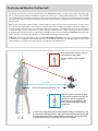
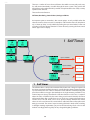
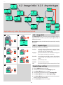
True Focus and Absolute Position Lock
The obvious situation that would most benefit from using True Focus would be a fashion shoot with a fairly wide angle
lens at a large aperture setting and where the central area of the image is clothing while retaining focus on the model's
face. Ideally, a fairly controlled and static flow should be planned on (this means a change of pose by the model should take
place only after captures and the photographer must resist crouching down, or leaning forwards or backwards too much
before capture).
With the lens at its widest aperture setting, a normal autofocus setting is made on the model's face (A), and the camera
focus locked. The composition is then changed to include more of the clothing (B), but the locked focus setting now
extends beyond the model's face at (B) according to the laws of geometry. This will naturally result in an image where
much of the subject closest to the camera and the model's face will be unsharp. Solutions involving manual focus/focus
lock/resetting of multi-point sensors are distracting to workflow and prone to error. Making a True Focus setting at (A) will
ensure that focus is automatically adjusted in accordance with the change of camera angle.
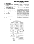
True Focus uses yaw rate technology and by way of the Absolute Position Lock (APL) processor, logs camera movement
as the basis for an extremely rapid compensatory focus reset without any shutter lag. The H4X’s firmware then further
perfects the focus using the precise data retrieval system found on all HC/HCD lenses.
A normal autofocus setting is made on
the model's face and locked.
A
The focus setting is approximately
2.5m.
A - ca
. 2.5 m
B - ca.2.5 m
Distance when camera perpendicular ca. 2.4 m
B
B A
A
B
When the camera is swung back down,
B, the locked focusing distance of 2.5m,
according to the laws of geometry,
extends beyond a perpendicular line
drawn down from the face, creating
unsharpness.
If a True Focus setting instead of a normal autofocus setting is now made at A and
the composition changed back to B again, the camera will automatically calculate
and adjust the focus of 2.5m to approximately 2.4m, which is the actual camera
to perpendicular distance. The model's face is now sharp again.
33
H4X
True Focus
True Focus can be used in combination with other autofocus settings to achieve various functions.
Activated by shutter release button – True Focus retained
1
MENU
2
3
1/2 !
4
In this mode the autofocus function is effectively converted into the True Focus function. That is, focus is set by half-pressing the shutter release button. Remember,
though, that the True Focus function is retained until turned off in Custom Options.
1. In Custom Options, select # 32 (True Focus in AF-S) with the front control wheel.
Select 'ON' with the rear front control wheel. Save.
2. Aim camera at important area in subject and half-press the shutter release button.
3. Wait for the True Focus icon to appear (in the viewfinder) and the audio confirmation
signal.
4. Maintain the half-press and recompose the picture. Press fully to expose. The True Focus
icon disappears from the viewfinder. True Focus function is retained.
Temporarily activated by a selected 'User' button – Autofocus retained
1
MENU
2
3
4
In this mode the True Focus function is activated by pressing an assigned button. This
produces a 'one-shot' setting where the camera reverts to its original Autofocus setting
after capture. Useful if you want to quickly switch back and forth between True Focus
and normal Autofocus. Works with or without a Custom Options #32 setting.
1. In Custom Options, select the desired button to reassign with the front control wheel
(M.UP button in this example). Select 'True Focus' with the rear control wheel. Save.
2. Aim camera at important area in subject and press the selected button (the grip display
now indicates AF-T mode).
3. Wait for the True Focus icon to appear (in the viewfinder) and the audio confirmation
signal.
4. Recompose the picture and press shutter release button (camera does not re-focus
because it is temporarily in AF-T mode). The True Focus icon disappears from the viewfinder. Camera reverts to AF-S.
Note that camera reverts to AF-S if the focusing ring on the lens is moved.
Activated by True Focus button – Autofocus deactivated
1
AF
On
2
3
In this mode the True Focus function is activated by pressing the True Focus button.
Normal autofocus is de-activated, therefore, pressing the shutter release button will
not reset the focus. Useful when many shots are required with the same focus setting.
1. Press AF button. Select 'True Focus' with the front control wheel. Save.
2. Aim camera at important area in subject and press True Focus button.
3. Wait for the True Focus icon to appear (in the viewfinder) and the audio confirmation
signal. Recompose the picture and press shutter release button.
Note that the True Focus adjustment is applied to all following captures until True
Focus button is pressed again (when a new adjustment is made).
Activated by a selected 'User' button – Manual focus retained
1
MENU
2
3
In this mode the True Focus function is activated by pressing an assigned button. This
produces a 'one-shot' setting where the camera reverts to its original Manual focus
setting after capture. Pressing the shutter release button will not reset the focus. Useful
when many shots are required with the same focus setting.
1. In Custom Options, select the desired button to reassign with the front control wheel
(M.UP button in this example). Select 'True Focus' with the rear control wheel. Save.
2. Aim camera at important area in subject and press the selected button.
3. Ensure that the True Focus icon appears in the viewfinder.
Recompose the picture and press shutter release button. The True Focus icon disappears
from the viewfinder. Camera reverts to AF-S.
Note that the True Focus adjustment is applied to all following captures until the True
Focus button is pressed again (when a new adjustment is made).
34
H4X
Note
Note
Some lenses have extra characteristics that require further
explanation. For example, the autofocus range on the HC 4/120
Macro lens can be limited by a specific setting on the camera
allowing for near range, far range or full range. This only
appears on the grip display together with that particular lens.
The autofocus function is not possible with certain combinations of lenses and accessories. However, a warning is displayed
which disappears after confirmation.
Further information can be found in the "H-system Lenses & Hsystem Lens Accessories" booklet that accompanies each lens.
The booklet can also be downloaded from the Hasselblad website.
Also, see note here regarding HCD lenses!
Tip
Tip
For users who prefer manual focus control but would like the
benefits of autofocus, one method is to set the AE-L button (or
any user button) to AF (Single) drive.
The True Focus function can also be combined with other autofocus modes for specific situations.
The main subject can then be centered and the AE-L pressed,
to ensure correct focus. The camera reverts immediately to
manual focus control when the button is released.
Therefore, you can recompose the picture without having
to maintain pressure on the release button in order to retain
the newly automatically made focus setting (AF-T can also be
used).
Tip
To expand your range of lenses, consider using a CF adapter
to allow you to use most of the lenses from the Hasselblad Vsystem.
35
H4X
6
Light Metering &
Exposure Control
Three metering methods
Five exposure methods
Extremely accurate light metering
The light metering system of the viewfinder is capable of
selective sensitivity producing three reflective metering
methods: Average, CentreSpot and Spot. All methods are
measured in increments of 1/12 EV. Information transfer is
rapid and automatic ensuring consistently correct exposure
settings even in difficult and changeable lighting situations.
Light measurement is made through the lens (TTL) and
exposure is controlled manually or automatically by the con
trol wheels and/or settings. The information is visible on both
the grip display and the viewfinder display.
Photo: Lyle Owerko / Hasselblad Masters
A great deal of control is available ranging from 100% manual
through to sophisticated fully automatic by way of the various
exposure methods: Manual, Aperture priority, Shutter prior
ity, Program and Program variable.
36
H4X
Light metering and exposure control
Two primary factors have to be considered when making exposure control choice,
namely, metering method and exposure method:
Metering method determines in which manner the light measurement is made and
how much of the image is taken into account (Centre Weighted, CentreSpot and Spot).
Exposure method involves the parameters and deciding factors about how the light
measurement is translated into aperture and shutter speeds. Here the choice is about
the camera controls and their effect on the result or suitability for the subject. Included
in this choice is the type of automation too (Manual for 100% user control, Aperture
priority, Program, etc for automated control).
Some methods and modes are much more suited to various situations and applications
than others, while some depend to a greater degree on personal preference and ways
of working. A discussion of the points to consider in this context is beyond the scope of
this manual.
Since the light measuring system is TTL, filter factors, lens extension/extension ring fac
tors, etc, are automatically taken into account for average purposes. However, some
combinations of methods and equipment can cause slight discrepancies for various
reasons and therefore for critical work you should make alternative captures to suit per
sonal preference.
Note
Exposures are displayed on the grip display to within 1, 1/2 and 1/3 EV tolerances (dependent on setting). This means that ‘half-stops’ are shown in a form that can differ from more
traditional displays. For example, the position between f/ 8 and f/11 is displayed as f9.5 and
likewise the position between 1/30s and 1/60s is displayed as 45. Therefore a display showing ‘f 9.5 45’ simply means ‘f/9.5 at 1/45 second’. The appearance of an ‘s’ after the shutter
speed signifies whole seconds so, for example, ‘32s’ on the display signifies an exposure
time of 32 seconds, not 1/30.
37
H4X
Metering method
1
There are three metering modes available. All three are reflective methods (measuring
the light reflected off various selected parts of the subject according to method) and
are through the lens (TTL). These have the following designations (with their respective
display symbols):
EXP
– Centre Weighted
– CentreSpot
– Spot
See under 'Appendix' for details of sensitivity distribution.
2
Centre Weighted: Commonly used for ‘average’ light situations where there is no
particular dominance of light or dark areas across the tonal range.
R
CentreSpot: Emphasizes the central section of the focusing screen. This provides a bal
anced assessment and is a typical choice where the main subject is in the centre of the
image.
Spot: The sensitive area is marked by the central spot on the viewfinder screen. Any
parts of the image outside of this area will not affect the exposure reading. This provides
a very accurate measurement of specific tones. Typically used in the zone system and
similar light measuring situations where maximum control is required. Also excellent for
tonal comparison measurements. The spot mode can display ‘zones’ instead of EVs in
the viewfinder display (see Custom Options #14).
Selecting metering method
Proceed as follows with the camera in active mode:
DRIVE
1. Press the EXP button on the viewfinder.
2. Turn the rear control wheel (in either direction 2a) to successively access the three
choices: Centre Weighted, Centre Spot and Spot 2b.
3.Press Save (DRIVE button) to retain the setting.
Save
Exposure method
3
Exposure can be controlled either manually or by using one of four automatic modes.
These have the following designations on the grip display:
M – Manual
A – Aperture (priority)
S – Shutter (priority)
P – Program
Pv – Program variable
In each mode you can see both the aperture and the shutter speed information on the
grip display and on the viewfinder display.
In manual mode, aperture is set by the front control wheel and the shutter speed by the
rear control wheel unless set otherwise in Custom Options #27.
In the automatic modes, the aperture and shutter speed settings are controlled by the
camera, either partially or completely according to setting. Within this mode there are
four choices.
(Please see the Appendix for P and Pv mode charts that describe the aperture and shut
ter speed setting combinations.
38
H4X
1
Manual Exposure – M
2
Manual mode will provide total user control of the shutter and
aperture settings.
EXP
To set the Manual mode, proceed as follows with the camera in
active mode:
R
1) Press the EXP button on the viewfinder.
2) Turn the front control wheel in either direction until you reach
M (Manual).
3)Press Save (DRIVE button) to retain the setting.
3
In this mode the shutter speed and aperture settings are manually
chosen by turning the front and rear control wheels.
The standard exposure setting is obtained when the pointer over
the exposure scale is positioned above the central index (in the
viewfinder display).
DRIVE
Any deviation from this standard setting is displayed by:
Save
• the pointer appearing elsewhere than above the central index
and
4
• by figures above the scale representing the amount of adjustment in EVs.
A ‘+ 0.7’ above the scale in the display, as in illustration 4
for example, would indicate a ‘0.7 EV overexposure’ setting.
Conversely, a ‘-2’ , for example, would indicate a ‘2EV under
exposure’ setting. Note that the appearance of a +/- symbol on
the grip and viewfinder displays in manual mode means that a
change has been made to the exposure compensation setting.
See later section on Exposure compensation.
The actual aperture settings and shutter speeds are indicated
to the right of the exposure scale in the conventional manner.
(Note: ‘full-stops’, ‘half-stops’ and ‘third-stops’ are also displayed,
according to setting (see ‘increment setting). For example, a
setting between f/8 and f/11 will appear as f/9,5 if ‘half-stop’ is
chosen).
Automatic Exposure – A, S, P, Pv
Automatic exposure provides a choice of two ways of controlling
shutter speed and aperture settings semi-automatically and two
ways fully automatically:
Aperture priority: A - The aperture is manually chosen by you
by turning the front control wheel, and the shutter speed is auto
matically chosen by the camera.
Shutter priority: S - The shutter speed is manually chosen by
you by turning the front control wheel, and the aperture is auto
matically chosen by the camera.
Programmed: P - In this mode, an aperture / shutter combi
nation is chosen by the camera according to the EV measured
(metering method remains as your choice), though only within
pre-set appropriate limitations to suit various requirements and
applications.
39
H4X
1
Programmed variable: Pv - This mode is very similar to Pro
grammed, except with the additional parameters of lens focal
length being automatically taken into account. For example,
long shutter speeds will automatically be avoided with a long fo
cal length lens.
2
EXP
F
To set one of the modes, proceed as follows with the camera in
active mode:
1) Press the EXP button on the viewfinder.
2) Turn the front control wheel (either direction) until you reach
the required setting.
3) Press Save (DRIVE button) to retain the setting.
3
DRIVE
In Automatic mode the front control wheel selects alternative
aperture /shutter combinations while maintaining the same EV
and the rear control wheel alters the amount of exposure com
pensation. The compensation appears as a +/- symbol on the grip
display and viewfinder display (illus. 4).
Save
4
Variations (chosen by using the front control wheel) from the
specific combination selected by the P or Pv mode are signified
by a double arrow symbol appearing between the aperture and
speed settings (illus. 5) on the grip display. These new variations
provide the correct exposure but in different combinations.
5
AE- L button
1, 2, 3, 4, 5, 6
This button has two main functions that can be incorporated
in various working methods involving exposure locking. It also
has an extra function for the flash measure capability (see AE-L
section under Flash). The AE-L button can:
Tip
a) lock an EV setting in manual and automatic modes.
b) be used as a Zone System placement button.
a) When the button is pressed (fig 1), the light metering facility is
locked to the EV setting at that moment. An L (= locked) symbol
appears between the shutter speed and the aperture indication
(fig 2) on the grip display and viewfinder display to confirm the
status. Press the AE-L button again to unlock (toggle function).
Aperture and shutter speed settings can both be changed
even while the busy light on digital back is flashing.
1
In the locked setting, the aperture and shutter speed become
interlocked. In this way, a new aperture/shutter combination that
still represents the same EV, can be rapidly chosen. For example,
if you set the shutter at 1/125s and the aperture at f/8 and lock
them together, you can access new EV-equivalent combinations
of, for example, 1/30s a f/16 or 1/500s at f/4 just by moving the
front control wheel.
2
In practice this means you could, for example, in auto mode, posi
tion the metering area (spot setting) over an area in the subject
that you determine to be equivalent to a mid-grey and lock it with
the AE-L button. You can then recompose the picture with the
metering zone positioned over an area much brighter or darker
while still retaining the original exposure setting and choose a
new combination of aperture and shutter speed settings.
Tip
Access to the B and T shutter speed settings can be temporarily hidden. See Custom Options #35.
40
H4X
b) The AE-L button also allows the spot metering function to
make zone placements. When the AE-L button is pressed, the
metered area is saved as a mid-grey (Zone 5). When the spot area
is then placed over another part of the scene, the new area is then
compared to the saved area and the difference can be read off
the scale seen in the viewfinder. For example, in a landscape situ
ation you could meter the foreground, lock the reading with the
AE-L button (thereby locking that area to be reproduced as the
equivalent to a mid-grey 18%), point the camera at some rocks to
see by how much darker they are compared to the foreground by
the EV difference read off the scale (illus 3).
3
New metered area is 1.8 EV lower than the area
metered when the AE-L button was pressed.
4
If you have chosen Spot together with Zone display (see Custom
options #14 for settings) as well as one of the automatic modes
A, S, P or Pv, point the spot marking at an area that you decide
should be a Zone 5 and click the AE-L button (illus 4). The meter
will now display different parts of the subject as zone values (illus
5) in the viewfinder display, instead of EV deviations, as you move
the spot marking over the subject. (Included are Lo and Hi (illus 6)
to signify areas beyond the range of the sensor).
AE-L button pressed to call the metered area
‘Zone 5’.
5
Alternatively you can choose to re-classify an area as another
zone and then check the rest of the subject to see how other
areas fall on the zone scale. Do this by following the above pro
cedure and then turning the rear control wheel until you see the
new desired zone value in the viewfinder display. You will also
see the new exposure that will now produce that new zone. For
example, you might have measured a rock at zone 5 but wish
to make it darker. By moving the rear control wheel you could
re-classify it as zone 4. You will then be able to see, for example,
whether white clouds are now falling within the exposure range
by their new zone classification.
Metered area reads ‘Zone 8’.
6
Metered area above ‘Zone 10’.
Alternatively, you can also pre-set the initial zone reading in order
to save time and effort where there is no freely available ‘zone
5’ subject for light measuring. For example, you might be on a
sandy beach where you know that sand is normally classified as
zone 6. You can pre-programme the zone placement by hold
ing down the AE-L button while choosing the new zone value
and turning the front control wheel until zone 6 appears. All new
placements will then be zone 6.
41
H4X
Exposure compensation/Quick Adjust The exposure compensation function, for both manual and
automatic modes can be set from -5 to +5 EV, in 1/3, 1 or 1/2 EV
increments (Custom Option #3) and is visible above the scale in
the viewfinder and as a ± symbol on the grip display.
Custom Options #3, #17 and
#23 used to deactivate and
alter the settings for the rear
control wheel/Quick Adjust
function.
The quickest way to make an adjustment in auto-exposure mode
is use the rear control wheel.
To make a temporary compensation setting in an auto-
exposure mode using the Quick Adjust function:
a) Select chosen auto exposure mode.
b) Turn the rear control wheel to select the chosen amount of
compensation.
The amount is displayed in the viewfinder as both an EV
figure complete with a ‘minus’ or ‘plus’ prefix and as a marker
above a ‘minus’ to ‘plus’ scale.
Default settings provide 1/3 EV compensation and an immediate
clearing of the setting after capture.
However, in Custom Options #3 you can select 1/3, 1 or 1/2 EV
increment changes, in Custom Options #23 you can choose to
retain the setting after capture and in Custom Options #17 you
can deactivate the function.
1
2
+/-
To make a fixed exposure compensation setting, proceed as
follows with the camera in active mode:
F
1) Press the +/- button on the viewfinder.
2) Turn either the front or rear control wheels to increase or
decrease the amount of compensation in 1/3 EV steps.
3) The amount is displayed in the viewfinder as both an EV
figure complete with a ‘minus’ or ‘plus’ prefix (A in illustration), and as a marker above a ‘minus’ to ‘plus’ scale (B in
illustration).
4)Press Clr (AF button) to reset any compensation back to zero.
5) Press Save (DRIVE button) to retain the setting.
6) A ‘±’ symbol is then displayed between the aperture and shutter speed setting as confirmation of the setting.
R
3
A
B
4
AF
Clr
5
6
DRIVE
Save
42
H4X
Drive
There are two drive modes, Single and Continuous, accessed by pressing the DRIVE button on the grip.
Single
2
1
F
DRIVE
In Single mode, an exposure is made when the shutter release
button is pressed and the camera is made ready for the next ex
posure. To make the next exposure however, you must first re
lease the shutter release button and then press again.
In camera active mode:
Save
1) Press the DRIVE button on the grip.
2) Turn the front control wheel to: Single
3)Press Save to store the setting.
3
Continuous
DRIVE
In Continuous mode, the camera automatically makes exposures
and makes ready for the next exposure in a continuous manner as
long as you maintain pressure on the shutter release.
Save
In camera active mode:
1) Press the DRIVE button on the grip.
2) Turn the front control wheel to: Continuous
3)Press Save to store the setting.
Multi exposure (Applies to film magazine use only)
Film magazine use only
2
1
F
DRIVE
Save
Enter
3
4
DRIVE
Save
R
In Multi exposure mode, the camera does not advance the film af
ter the first exposure, only at the end of the pre-determined num
ber of exposures. The frame options are: 2, 3, 4, 5 and ‘No limit’.
In camera active mode:
1) Press the DRIVE button on the grip.
2) Turn the front control wheel to: Multi exp.
3) Turn the rear control wheel to select the number of frames
required.
4) Press Save (DRIVE button) to store the setting.
5) The LCD will display firstly that no frames have been exposed
in the multi-sequence (For example, in the case of a three
exposure setting the display will be Exp:0/3).
6) Press the shutter release button to make the first exposure.
7) The LCD will display how many frames have been exposed
in the sequence (In the case of a three exposure setting the
display will now be Exp:1/3. After the next exposure, the LCD
would then display 2/3 etc)
8) You can change your mind at any time to exit the sequence
by pressing the DRIVE button to advance the film to the next
frame. The camera is then prepared for another new multi
exposure sequence according to the initial setting.
43
H4X
7
Profiles
Profiles not only allow for rapid setup in changing working
environments but also ensure an element of security.
Photo: Mark Holthusen / Hasselblad Masters
44
H4X
Profiles
The profiles feature allows rapid access to pre-determined combinations of settings that
increase the speed and security of workflow. One example might be in a social situa
tion where there might be a need for formal outdoor portraiture followed by informal
indoor handheld flash-assisted wide-angle shots, both situations requiring very different
settings in a stressful environment. By predetermining the relevant settings required be
forehand for each situation, they can be saved collectively as a profile. By calling up the
profile, you can then be assured that all the settings are correct at the press of one button.
For example, you might choose – autofocus single, bracketing, programmed exposure,
etc – for outdoors. Once set, you would click on the red PROFILES button, select a pro
file name and press SAVE. A new name can be entered for the new profile - ‘Outdoors’,
for instance - and saved again. New settings are made for the indoor shots changing
to flash, Pv setting, etc and the procedure repeated. By simply accessing ‘Outdoors’ or
‘Indoors’ in the profile list, all the relevant settings will be instantly and correctly imple
mented to match the situation.
There are eight profiles: Default, Full auto, Studio, Fill flash. and four Spare reserved
for customization. All except Default can be changed and renamed.
The pre-set profiles feature the following:
Default: normal flash sync, autofocus (single), single drive, auto exposure (aperture
priority), centre weighted metering, user button - None.
Full auto: normal flash sync, autofocus (single), single drive, programmed exposure,
centre weighted metering, user button - None.
1
Studio: normal flash sync, manual focus, single drive, manual exposure, spot metering,
user button - AF.
DRIVE
Fill flash: normal flash sync (adjusted output -1.7EV), autofocus (single), single drive,
auto exposure, centre weighted metering.
Save
Spare: customized profiles.
The default setting is highlighted on the display for easy and rapid access. Access to
profiles lower on the list is via a scroll bar visible on the right of the display. Rotate the
rear control wheel to bring them into view.
2
ON•OFF
PROFILES/ESC
All user profiles can be restored to default values again simply by removing the battery
and holding down the MENU and DRIVE buttons together and while keeping them
depressed, replace the battery. There will be an audible signal that denotes the restoration.
3
Note
F
R
4
All settings are stored when a profile is created. This includes the ISO, white balance, color
temperature and color tint settings that were current at the time the profile was created.
These profile settings will override the settings in use at the time the profile button was
pressed. In other words, remember to check for unintentional ISO, white balance or color
temperature changes when using profiles. (Color tint is not a user setting but is stored after
a manual white balance has been made).
Making a profile
DRIVE
Save
1) Activate the camera and go through the various settings (for example, autofocus,
aperture priority, fill flash exposure compensation, etc.) you require for the particular
purpose and save them as you go.
2) When all the required settings have been made, click (not press!) the PROFILES
button (ON.OFF button) on the grip and the profile screen will appear.
45
H4X
1
3) Use the scroll bar to go through the list of profiles. Choose a
Spare profile or a named profile (except Default). You can
either save the new profile under the original name or you
can change it
4)Press Save (DRIVE button). The Profile name screen is then
displayed where you can rename the profile to what suits you
(see under Image Info 4.2 for procedure details).
To use a profile from the main screen, press the PROFILES button
to reach the profiles screen again. Scroll down the list to the pro
file you want and then press the Load (AF) button. All the saved
settings will then be automatically implemented.
2
ON•OFF
PROFILES/ESC
3
Note
If you decided to change the settings but nevertheless keep the
Profile name on the list, the new set of parameters will be retained
under that name. That is to say, the settings will not be the same
as listed here, despite the name. It might be safer practice to
always change the profile name to avoid later confusion.
AF
Load
Using profiles
1
2
1) From the main screen, click PROFILES (ON.OFF button) on
the grip and the profile screen will appear.
2) Use the scroll bar to go through the list and highlight the
desired profile.
3)Press Load (AF button). The camera is now set according to
all the parameters stored according to the name.
F
R
ON•OFF
PROFILES/ESC
3
Changing a profile name
You can change a profile name (except ‘Default’) at any time.
4
Proceed as follows:
1) From the main screen, click PROFILES (ON.OFF button) on
the grip and the profile screen will appear.
2) Scroll through the list (front or rear control wheels) and highlight the desired profile.
3)Press Load (AF button).
4)Click PROFILES (ON.OFF button) again.
5)Press Save (DRIVE button) The Profile name screen is then
displayed where you can rename the profile to what suits you
(see under Image Info 4.2).
AF
ON•OFF
Load
PROFILES/ESC
5
Tip
DRIVE
ISO/WB
Save
MENU
46
To quickly reset all profiles back to the
original factory settings:
1. Remove battery.
2. Wait 5–10 seconds.
3. Replace the battery while keep
ing both the Menu and IS0/WB
buttons pressed.
H4X
8
Custom settings
– controls and displays
This section describes the features that can be exploited to
obtain the optimum in customized workflow.
The custom options are designed to work for you in the back
ground, ensuring security and also helping to bring down the
barriers between you and capturing the image. Each one can
be changed to suit your preferences so that the whole camera
becomes a reflection of the way you like to work.
Photo: Alexandfelix / Hasselblad Masters
47
H4X
General overview of
camera menu
MENU
Text setting
Self timer options
Bracketing options
Interval
options
Settings options
System status
Custom Options
Digital
This section is
primarily only
accessible with
Hasselblad CF/
CFH use.
3rd party digital
backs, may or
may not initiate
the Digital screen
and its settings.
Please refer to
the appropriate
user manuals for
information.
48
H4X
The H4X features the advantage of multiple customization
of settings. This means that your personal choice of settings,
and thereby appearance of various combinations of symbols
on the display at any time, will not necessarily be the same
as many of the screens illustrated in this manual.
Menu charts – general
Throughout this manual you will find charts to explain the
steps and procedures required to alter the various settings.
These charts are laid out to graphically illustrate in a simple
manner how to navigate through the menus. While they
include all the information that would be presented on the
display relevant to that section, they cannot illustrate all
the possible combinations of the various symbols seen on
a screen at one time as that would be impractical and too
confusing. If you are familiar with mobile/cell phone menus,
for example, then the design of the layout and working
practice will not be unfamiliar.
To simplify the descriptions, reference is often made to a
‘main’ or standard screen. Apart from default settings, there
is no actual standard setting in the normal sense and there
fore you create your own ‘standard’, which of course can be
changed at any time.
The ‘main’ screen is therefore the one you have currently
created and is the one visible on the display when photo
graphing (except where a particular mode is in actual
operation, such as self-timer, for example).
You should find that, in practice, working your way through
a menu on the camera is a good deal simpler and more
obvious than the written explanation implies!
In the descriptions, various terms are used regarding menu
navigation. Menus have ‘trees’, for example, which describes
their imaginary graphical layout where you could trace a
navigational path along its ‘branches’. Each new section, or
stopping off point on the branches, seen on the display is
called a ‘screen’. Therefore a screen is the graphical display
of where you are on the menu and represents the current
state of settings.
Symbols used in the illustrations
F
R
Use front control wheel
ISO/WB
(direction depends on user setting)
Save
Use rear control wheel
(direction depends on user setting)
Press button or turn wheel
Choose ON
Main direction of path through menu
ISO/WB
Choose ENTER
On
Functions in loop on menu
(by pressing DRIVE button on grip)
MENU button on the grip
AF
(by pressing the DRIVE button on grip) The
new setting will be saved and chosen action
can be carried out. Setting will be retained
until changed.
A loop means that the available functions on
that particular branch of the menu can be
successively accessed in either direction of
the control wheels without a break in flow.
That is, you could turn the wheel clockwise
or anti-clockwise to arrive at the desired func
tion.
MENU
Enter
Choose Save
(by pressing AF button on grip)
The main path traces step-by-step the path
that has to be taken through the various
branches of the menu tree as they appear on
the display to reach the relevant functions.
49
H4X
There are a number of more advanced features that while not necessarily used every
day still remain immediately accessible through the menu system. They provide the
integral finesses that make the H4X a powerful and sophisticated tool to satisfy a variety
of professional demands.
There are five main functions:
Self timer, Bracketing, Interval timer, Settings and Drive.
An important point to remember is that certain options are only available when the
relevant screen has been accessed. For example, in Self Timer the choice of ‘delay/mirror
up’ or ‘mirror up/ delay’ is only available (by turning the rear control wheel - lower row
on display) when the relevant function has been chosen (by turning the front control
wheel - upper row on display)
1 Self Timer
options available
2 - 60 s
options available
DELAY / MIRROR UP
or
MIRROR UP / DELAY
options available
MIRROR GOES DOWN
or
MIRROR REMAINS UP
1 Self timer
The self timer allows a delay in the activation of the shutter and a change in sequence of
the mirror movement. Normally the mirror is raised before the shutter is tripped creating
a pause between the two actions to minimize camera vibration. However, during this
pause there will be no image in the viewfinder and no light metering available for any
eventual exposure change. Therefore the Self timer function can be set to a sequence
where the delay is followed by the mirror being raised instead. Normally the mirror
will instantly return after a capture but you can also choose a setting where the m
irror
remains raised. The Self Timer can be set to provide virtually vibration-free shutter
release. It can be used instead of a remote release cable/cord/device when split-second
timing is not critical. The camera’s exposure settings (Manual or Auto) will be according
to the light metering requirements just prior to the mirror being raised so choose the
method accordingly with long delays in very changeable lighting conditions.
50
H4X
1
Self timer setting
2
The Self timer function is set in the following manner:
F
MENU
1) Press the Menu button on the grip.
2) Turn the front control wheel until Self Timer appears.
3)Press Enter (Drive button) on the grip.
4) Turn the front control wheel to access the options, that are:
Delay 3
4
DRIVE
Mirror sequence
F
Mirror Up / Mirror Goes Down
Enter
5
6
R
5)When Delay is highlighted - turn the rear control wheel
to choose a delay range from 2 - 60s in 1s intervals.
6) Turn the front control wheel again to choose Delay / Mirror
Up, Mirror Up/ Delay sequence . When highlighted
turn the rear control wheel to choose.
R
‘Delay’ highlighted with drop
shadow. 10 seconds chosen.
Mirror sequence highlighted.
‘Delay first, then mirror raised’
chosen as option.
7
8
Delay / Mirror Up sequence =
Delay for set amount of time – mirror raised – capture made.
Mirror Up/ Delay sequence =
Mirror raised – delay for set amount of time – capture made.
7) Turn the front control wheel again for
Mirror goes down / Mirror remains up - .- choice. Turn
the rear control wheel to choose.
Mirror goes down =
Mirror returns to its normal position and the camera is made
ready for the next capture.
Mirror raised =
Mirror remains in raised position. No image is visible in the
viewfinder until M UP button pressed.
8)Press On (AF button). Note that this now reads Off and the
line of text at the bottom of the screen reads ‘Self timer on’.
9)Press SAVE (DRIVE button) to save the setting.
10)Press ENTER (DRIVE button) again from the Self Timer
screen to activate the function.
11)Click On (AF button).
12)Half-press the shutter release button to standby mode for this
function (press the shutter release button again (full press)
for activation) or full-press the shutter release for immediate
activation.
F
AF
On
Mirror down /up highlighted.
‘Mirror down after capture’
chosen as option.
9
DRIVE
10
Save
11
(A drop shadow will be displayed beneath the selected symbol,
for example
)
DRIVE
Enter
12
AF
On
Tip
Check the lower text-row on the screen for ON or OFF
status.
51
Note
Tip
You can halt the sequence by
clicking the ON / OFF ( ESC)
button.
Press the Mirror Up button
twice within 0.5s to access the
self timer mode directly.
H4X
2 Bracketing
options available
2 frames
or
3 frames
or
5 frames
options available
options available
1/3 EV or 1/2 EV or
1 EV or 2 EV or 3 EV
Tip
A bracketing sequence can be
stopped mid-sequence by pressing
the ESC (ON.OFF) button.
Tip
Check the lower text-row on the
screen for ON or OFF status.
2 Bracketing
The bracketing function provides an automatic series of captures; one at the standard
exposure setting (Manual or Auto) and the others with pre-determined deviations in EV
from the standard exposure. This is particularly useful for images containing a very wide
tonal range, for example.
Firstly you make an assessment concerning the number of extra frames required, the
order in which they should be taken, and by how much the EV deviation there should be
and the setting made accordingly. The first metered exposure (Manual or Auto) is the EV
that determines the calculations for the bracketing sequence.
Note the difference in operation between Single and Continuous drive settings:
• In Single you must press the shutter release button separately for every separate
capture until the sequence is finished.
Note
• In Continuous you can either maintain the pressure on the button to take all frames
without stopping or you can release the pressure on the button and press again to
continue to the end of the sequence without losing any frames within the set sequence.
See note at the beginning of this
section regarding the difference
between Single and Continuous
drive settings. In both cases, the
bracketing function is automatically
reset for a new sequence.
52
H4X
1
Bracketing setting
2
The Bracketing function is set in the following manner:
1) Press the Menu button.
F
MENU
2) Turn the front control wheel until Bracketing appears
3)Press Enter (Drive) button on the grip
4) Turn the front control wheel to access the options, that are:
Number of Captures (the number of captures required in the sequence)
3
DRIVE
Sequence (the sequential order of the over- or underexposures)
4
F
Step (the amount of EV variation from the standard exposure setting)
(A drop shadow will be displayed beneath the selected symbol, for
)
example
Enter
5
6
R
Number of captures highlighted.
3 captures chosen as option.
5)In
turn the rear wheel to choose the number of frames
required: 2, 3, 5, 7 or 9.
R
6)In
Sequence highlighted.
‘Standard, over, under’ chosen
as option.
turn the rear wheel to choose one of four sequences:
A: Standard, Over, Under
B: Standard, Under, Over
C: Over, Standard, Under
D: Under, Standard, Over
7)In
turn the rear wheel to choose the amount of EV variation
required: 3, 2, 1, 1/2, 1/3 EV.
8)Press Save (Drive button) to save the setting.
A
B
C
7
9)Press Enter (Drive button) again from the Bracketing screen to
activate the function. Press On (AF button). Note that this now
reads Off and the line of text at the bottom of the screen reads
‘Bracketing on’.
D
8
DRIVE
R
Half-press the shutter release button to standby mode for this
function (press the shutter release button again (full press)
for activation) or full-press the shutter release for immediate
activation.
To escape from this mode press Menu, then Enter (Drive button
on the Bracketing screen, then Off (AF button).
Save
9
Step highlighted.
1/3 EV variation chosen as
option.
AF
On
DRIVE
Enter
EXAMPLE
EXAMPLE
Screen after Bracketing setting
activated indicating 3 frames
remaining in a Standard, Over,
Under, sequence with no adjust
ment to the next frame.
Viewfinder display indicating
no adjustment to next frame
and three frames left in the
sequence.
Note
As an example, a 5 frame sequence with an EV 1 variation
setting at ‘Standard, Over, Under’ would produce: Standard (O EV
variation), +1EV, -1EV, +2EV, -2EV.
Note
The default setting is a shutter speed change in a bracketing
sequence. However, if the camera is set in Manual mode, you can
choose an aperture change instead (Custom Options - Bracket
param. in Manual #26)
53
H4X
3 Interval
options available
2 frames –
255 frames
options available
1 second −
1 hour
1
3 Interval
2
F
By using the interval setting, you can allow the camera to take
a series of captures automatically over a set period. This is often
required for time and motion studies, security surveillance, n
ature
study, etc. The exposure and focus settings (Manual or Auto) will
be according to the camera settings at the time of capture.
MENU
Interval setting
3
DRIVE
1)
2)
3)
4)
4
F
Enter
5
R
Number of captures (the number of captures required)
6
Interval duration (the time interval between the captures)
R
Number of captures highlighted.
2 frames variation chosen as
option.
Interval duration highlighted.
5 seconds variation chosen as
option.
7
8
DRIVE
Save
EXAMPLE
(The chosen symbol is indicated by a drop shadow)
5) In Number of captures, turn the rear wheel to choose the
number of captures required: 2 – no limit
6) In Interval duration, turn the rear wheel to choose:
1 second – 1 hour
7)Press Save (Drive button) to save the setting.
8)Press Enter (Drive button) again from the Interval screen
to activate the function. Press On (AF button). Note that this
now reads Off and the line of text at the bottom of the screen
reads ‘Interval on’.
Half-press the shutter release button to standby mode for
this function (press the shutter release button again (full
press) for activation) or full-press the shutter release for
immediate activation.
AF
On
DRIVE
Enter
Tip
Screen after Interval setting acti
vated indicating 3 shots remain
ing at 30 second intervals.
Press the MENU button on the grip.
Turn the front control wheel until Interval appears.
Press the ISO/WB (Enter) button on the grip.
Turn the front control wheel to access the options, that are:
Check the lower text-row
on the screen for ON or OFF
status.
54
Note
Tip
In Custom Options #29 you
can select an initial delay of
None, 2, 10, 60 seconds or the
interval time.
An Interval setting can be
stopped mid-sequence by
pressing the ESC button.
H4X
4 Settings / 4.1 Custom Options
options available
CUSTOM OPTIONS
1
4 Settings
2
F
From the Settings screen you can access four main sub-settings:
Custom options, Image info, Date & Time and System status
by turning the front control wheel. From each of these sub-
settings you can access further items for setting changes. Look at
the main menu chart to get an idea of where all the options are
on the menu tree.
MENU
4.1 Custom options
3
DRIVE
4
Press the Menu button on the grip.
Turn the front control wheel until Settings appears.
Press the ISO/WB (Enter) button on the grip.
Turn the front control wheel to access 4.1 Custom options.
Press the ISO/WB (Enter) button to access the 34 choices
available.
6) Turn the front control wheel to the desired Option.
7) Turn the rear control wheel to the desired Setting.
8)Press Save (Drive) button.
1)
2)
3)
4)
5)
F
Enter
5
DRIVE
6
F
Enter
7
R
8
DRIVE
In the following list, the options marked in red are the default
settings. So, in the case of the User button, for example, as None
is the default there will be no reaction from the camera until you
make a specific choice and save it.
Save
If you want to reset the camera to the default setting for all
options, press the ON.OFF button quickly to enter Profiles,
select Standard and then press Load.
Tip
Tip
As a shortcut to a specific user button (True Focus, AE-L, M.UP,
Stop Down) setting in Custom Options, press the MENU and
then the desired button with camera in active mode. After
making any changes, press the shutter release button to save
the new setting.
As a shortcut to Custom Options level, press the MENU button
twice with camera in active mode. The latest setting will auto
matically appear. After making any changes, press the shutter
release button to save the new setting.
55
H4X
Stop down button function
4.1 Custom options
• Stop Down
The following is a description of all thirty four Custom Options.
They are accessed by Menu > Settings > Custom Options. The
words and figures in red signify the default setting for that option.
Standby timeout
6
but can be reassigned to:
• B mode • T mode • Flash Measure •
Interval timer • Cycle LM mode • Expose •
Standby • Histogram • IAA toggle • Digital focus check • Delete last image • Grey
balance exposure • None • AF Drive • AElock • Self Timer • Bracketing • Mirror up
1
• 10s • 5s • 15s • 30s • None
Determines the amount of time the
camera remains active before it auto
matically reverts to standby mode (indi
cated on the grip display by the H4X logo).
Minimizes battery consumption.
M.UP button function
7
• Mirror up
but can be reassigned to:
EV increment
• Stop Down • B mode • T mode • Flash
Measure • Interval timer • Multi Exposure
• Cycle LM mode • Expose • Standby • Histogram • IAA toggle • Digital focus check •
Delete last image • Grey balance exposure
• None • AF Drive • AE-lock • Self Timer •
Bracketing
2
• 1/2 Step • 1 Step • 1/3 Step
Determines the amount of EV change
applied (per click of either the front or
rear control wheels) to either aperture or
shutter speed.
Exp adjust increment
Control wheel direction
3
8
• 1/3 Step • 1 Step • 1/2 Step
• Clockwise • Counter clockwise
Determines the amount of EV change ap
plied (per click of the rear control wheels)
when making fixed exposure adjustment
settings.
Determines the effect the direction of the
controls wheels have on a setting.
True Focus button function For example, by moving the front control
wheel to the left you can alter the aperture
setting from f/8 to f/6.8 to f/5.6 and so on.
By changing the wheel direction s etting
however, the same action of turning the
wheel to the left would then produce
the opposite effect, that is, the aper
ture settings would change from f/ 8 to
f/ 9.5 to f/ 11, and so on.
4
• True Focus
but can be reassigned to:
AF Drive • AE-lock • Self Timer • Bracketing
• Mirror up • Stop Down • B mode • T mode
• Flash Measure • Interval timer • Multi Exposure • Cycle LM mode • Expose • Standby
• Histogram • IAA toggle • Digital focus
check • Delete last image • Grey balance
exposure • None
AE-Lock button function
Flash ready exposure lock
9
• Yes • No
Allows you to make a capture before the
flash is fully charged. For use with integral
flash unit or other TTL compatible flash
units connected to the hot-shoe. Not valid
for flash units connected by the PC con
nector.
5
• AE-lock
but can be reassigned to:
Yes blocks the shutter until flash is ready.
Self Timer • Bracketing • Mirror up • Stop
Down • B mode • T mode • Flash Measure
• Interval timer • Multi Exposure • Cycle
LM mode • Expose • Standby • Histogram
• IAA toggle • Digital focus check • Delete
last image • Grey balance exposure • None
• AF Drive
No allows shutter release before flash is
ready.
56
H4X
Magazine exposure lock
Spot mode
10
14
• Yes • No
• Normal • Zone
Allows you to release the lens and auxiliary
shutter in camera body without a digital
back attached.
Determines how the camera behaves
when set to Spot Mode.
Normal makes the camera behave in the
same fashion as when set to Average or
Centre Weighted.
Yes blocks the lens shutter and auxiliary
shutter in camera body if the digital back is
not attached. Generates message on grip
display if attempted.
Zone makes the camera behave in the same
fashion as the Hasselblad 205FCC. That is,
the central spot is placed over a particular
area of the subject and the AE-L button is
pressed. The exposure is then calculated
assuming that the metered area is 18% grey
or Zone 5 and is indicated on the display
as Zone 5. Alternatively, the area can be
reassigned to another zone by turning the
rear control wheel.
No allows the lens shutter and auxiliary shutter in camera body to be released without the
digital back attached.
Lens exposure lock
11
• Yes • No
Allows you to release the auxiliary shutter
in camera body without a lens attached.
Then, when the camera is moved, the areas
within the central spot are indicated by their
zone values.
Yes blocks the release of auxiliary shutter
in camera body if there is no lens a ttached.
Generates message on grip display if
attempted.
Focus aid in MF
No allows a release of auxiliary shutter in
camera body without a lens attached.
Out of range exposure lock
Sets how the focus aid arrowhead LED
symbols appear in the viewfinder display
in manual focus mode.
12
Half press makes them visible when the
shutter release button is pressed half way.
• No • Yes
Always makes them visible all of the time
when camera is active.
Allows you to release the camera when ei
ther the aperture or shutter speed setting
is beyond the working range (indicated on
the displays by “–”).
Off disables them completely.
Yes blocks the shutter if beyond the working
range.
AF assist light
No allows the shutter to be released (1/800s
or 32s) if beyond the working range.
True exposure
15
• Half press • Always • Off
16
• Camera • Off • Ext flash
Allows projection of light pattern to assist
the autofocus system in poor light or low
contrast situations.
13
Camera sets the integral AF assist illumination to be always active.
• On • Off
Determines whether the exposure is
automatically adjusted to create a true
exposure setting. (See Appendix for full
explanation).
External flash activates the AF assist illumination projected by a suitable attached
external flash unit. When detached, however, the integral system is automatically used.
On allows the adjustment.
Off sets the AF assist illumination to remain
always inactive.
Off retains the normal setting.
Note
If using flash/strobe as the main light source
and 1/800s shutter speed, re-member to turn
off the True Exposure option.
57
H4X
Rear wheel quick adjust
Interval & Self Timer
17
22
• Yes • No
• Exit • Stay
Allows rear control wheel to make a rapid
EV adjustment (or EV compensation) in
auto-exposure mode.
Allows either the Interval or Self Timer
mode to remain active after a capture or
immediately return to standard setting.
Yes turns the setting on. By turning the rear
control wheel, the adjustment is made and
appears on both displays as a ± symbol between the shutter speed and aperture values.
The amount of deviation also appears above
the scale to the left of the aperture value on
the viewfinder display.
Exit clears the setting and produces an
automatic return to standard setting after a
capture.
Stay retains the setting after a capture.
AE lock / Quick adjust
No turns the function off completely.
Control lock
23
• Exp reset • Saved
Allows either the AE-Lock or Quick adjust
mode to remain active after a capture or
immediately return to standard setting.
18
• All controls • All except user • Wheels • Off
Sets the amount of locking used when the
Control Lock (FLASH) button is pressed.
Exp Reset clears the settings and produces
an automatic return to standard setting
after a capture.
All controls locks control wheels and
buttons.
Saved retains the AE-Lock or Quick adjust
settings after a capture.
Wheels locks only control wheels. They
remain operable in any setting mode, however.
Show EV
Off disables lock function.
24
• Yes • No
Film wind on
Allows the display of EV settings on the
grip display.
19
• Half Press • Direct
Yes enables the display.
Sets when the film will be advanced to the
first frame.
No disables the display.
Half Press advances the film only when the
shutter release is pressedto half press position.
Show ISO
25
• Yes • No
Direct advances the film automatically to
the first frame when the film holder is inserted or when the magazine is attached.
Allows the display of ISO settings on the
grip display
Yes enables the display.
No disables the display.
Beeper20
• On • Off
Sets the audible beeper signal.
Bracket param. in Manual
26
• Shutter speed • Aperture
On enables the signal.
Selects either the shutter speed or the
aperture as the parameter which changes
in a bracketing sequence when in Manual
exposure mode.
Off disables the signal.
Show histogram
21
• Yes • No
Shutter speed selects changes in shutter
speed.
Sets whether a histogram of a capture
appears on the display after exposure.
Aperture selects changes in aperture
settings.
Yes enables the setting.
No disables the setting.
58
H4X
Aperture control in Manual
27
True Focus in AF-S
32
• Front wheel • Rear wheel
• Off • on
Selects which control wheel changes the
aperture setting when in Manual expo
sure mode.
Re-assigns half press of shutter release
button to activate True Focus function in
stead of standard automatic focus (single)
Front wheel selects the front control wheel
to change the aperture setting.
Always return mirror
Rear wheel selects the rear control wheel to
change the aperture setting.
Low flash warning
33
• No • Yes
Automatically lowers mirror again for
viewing at the end of every mirror-up
sequence.
28
• On • Off
Controls the display of the ‘Low flash’
warning message and triangle.
AE lock at half press
• Off • On
ON enables the function.
Allows access to AE-lock without having
to use customizable button assigned to
other required functions.
OFF disables the function.
Interval timer initial delay
29
Hide B/T mode
• None • 2s •10s • 60s • Interval time
Hides access to B and T shutter speeds
allowing smoother transition from 1s to
1.4s when making shutter speed changes.
30
• Normal • Light meter
Allows choice of aperture indication
display (in Manual mode only).
Normal selects
(f5.6, f8, etc)
conventional
display
Light meter selects ‘light meter’ type
display (f5.6⁰, f8.⁵, etc)
Extra mirror-delay
35
• Off • On
Allows an initial delay before the first
capture of an interval timer function
operation.
Aperture indication
34
31
50 ms • 100 ms • 200 ms • None • 25 ms
Extends the delay period between the
mirror being raised and the opening of
the lens shutter thereby reducing the
negative effect of vibration on longer
exposure times.
59
H4X
Customizable button function list
The TRUE FOCUS, AE-L, STOP DOWN and M.UP buttons can all be reassigned to different functions. Default settings are as ac
cording to name.
None
Interval timer
The button has no function.
Initiates interval timer function.
True Focus
Cycle LM mode
Activates True Focus function.
Changes the light-metering method in a loop manner: Centre Weighted/
CentreSpot/Spot.
AF
Expose
Activates the AF system in any focusing mode. When the button is pressed
the AF system sets the correct focusing point automatically. This is a rapid,
accurate and handy way of using the AF system when the camera is set to
manual focus mode. In this manner you take advantage of the accuracy
and certainty of the autofocus system while retaining the control inherent in
manual focusing mode.
Acts as alternative shutter release button.
Standby
Sets the camera in standby mode to save battery consumption.
IAA toggle
AE-lock
Allows IAA rating change of last capture.
Activates AE lock function.
Self timer
Initiates self timer function.
The following functions may only be accessible with some
digital backs.
Bracketing
Histogram
Initiates bracketing function.
Recalls the last shown histogram on the grip LCD.
Mirror up
Dig. foc check
Controls the mirror up or down function (same function as the M-UP button).
Displays last exposure taken at 100% scale on digital backs with LCD.
Stop down
Delete last image
Stops the lens down.
Activate the delete function for the last image in a digital back.
(to be implemented at a later stage).
B mode
Sets the shutter speed to B exposure mode.
Grey balance exp.
T mode
Initiates a grey balance exposure using the marker frame to select the desired
tone.
Sets the shutter speed to T exposure mode.
Flash Measure
Initiates flash measure function.
1
MENU
3
1) Press the Menu button.
2) Press the button you want to
reassign (True Focus, AE-L, M.UP
or Stop Down).
This directly accesses the particular
button you chose at the Custom
options level in the menu.
3) Rotate the rear control wheel to
select the function you want the
button to activate.
4) Press the Save button.
2
4
DRIVE
Save
R
60
H4X
4.2 Image Info / 4.2.1 Imprint type
Applicable only when film magazine attached.
1
4.2 Image Info
2
The Imprint type facility controls the text that will appear along the
edge of each frame on a film. It is possible to imprint approximately 40
characters at one time.
F
MENU
Imprint Type records technical information automatically created by
the camera.
4.2.1 Imprint type
The following can be chosen as an option:
4
3
DRIVE
• Imp. Type 1 F
Enter
5
• Imp. Type 2 prints the relevant basic information only: aper
ture, shutter, and exposure correction.
6
DRIVE
prints the relevant information: aperture, shutter,
metering mode, exposure mode, exposure com
pensation and flash compensation.
F
DRIVE
Enter
Enter
7
• Date & Time
prints date & time only (the correct date and time
is set through the Settings menu under ‘Date &
Time’.)
• Text & Date
prints text plus date
• Text & Info
prints text plus basic info
• Text
prints text only (that you have created in 4.2.2 Text)
Imprint type setting
1) Press the Menu button on the grip.
2) Turn the front control wheel until Settings appears.
3)Press Enter (Drive button) on the grip.
4) Turn the front control wheel to access 4.2 Image info.
5)Press Enter (Drive button) to 4.2.1 Imprint type.
6)Press Enter (Drive button) again and turn the front control
wheel to select the desired option.
7)Press Save (Drive button) on the grip.
DRIVE
Save
61
H4X
4.2 Image Info / 4.2.2 Text
1
4.2.2 Text
2
MENU
3
In Text you can compose your own combination of letters, words, symbols, etc to be included in the metadata. The same procedure is also used
to change a Profile name.
F
1)
2)
3)
4)
5)
4
DRIVE
6) On the left side of the screen there is a small box frame containing an X symbol and two arrow symbols. By turning the
front control wheel, the selector cursor will enter the box and
by turning the rear control wheel the selector cursor will move
up and down.
• When the X in the box is highlighted and the Sel.(AF) button is pressed, the character highlighted in the text line lower
down the screen will be deleted.
• When an arrow in the box is highlighted, the text line cursor
moves along the text line in the arrow’s direction, moving
past every character with every click on the Sel.(AF) button
to the desired position. The highlighted character in the text
line can then be replaced by a new character chosen by moving the selector cursor out of the box, positioning it over the
new character to highlight it, and then pressing the Sel.(AF)
button.
• By turning the front control wheel, the cursor moves horizontally.
• By turning the rear control wheel, the cursor moves vertically
and introduces all available characters by scrolling the screen.
F
Enter
5
Press the Menu button on the grip.
Turn the front control wheel until Settings appears.
Press the Enter (Drive) button on the grip.
Turn the front control wheel to access 4.2 Image info.
Press the Enter (Drive) button to 4.2.2 Text.
6
DRIVE
Enter
62
H4X
1
2
3
4
5
6
Changing text - an example
Here is an example of how to change existing text (in this case the
word ‘Text’ to a copyright symbol plus a photographer’s name
-’Jens Karlsson’). See previous section 4.2 Image info for proce
dure description.
1) Start by accessing the Image info screen. On the text row
towards the bottom of the screen, the text line cursor is automatically placed to the right of the character that is to be
changed. Turn the front and rear control wheels to move the
selector cursor until the X symbol is highlighted.
2) Press Sel. (AF button) and the character will be erased.
3) Repeated pressing of Sel. will progressively erase all the
characters in the line.
4) After erasing unwanted text, turn the front and rear control
wheels until the desired character is highlighted by the selector cursor (in this case the copyright symbol) and press Save.
Note that more symbols have automatically appeared as you
scrolled down the screen.
5) Choose the next character in the same manner
(in this case a space) and press Save.
6) The capital letter ‘J’ has been highlighted and saved in this
example.
7) Repeat the procedure until all the letters and characters you
want appear. As you progress with more characters, those
to the left will temporarily disappear from the screen so that
you can see what you are adding. Don’t forget there is a
maximum of approximately 40 characters.
If you make a mistake you must remove each character singly
(see steps 1-3 above) until you reach where you want to make
a change and then return to the ‘Adding text’ procedure
again.
8) This example shows a completed 15 character text line with
symbols, spaces, upper and lower case (large and small)
letters.
7
8
63
H4X
4.3 Date & Time
Alert message when a
CF / CFH digital back is
attached
1
4.3 Date & Time
2
Adjust date and time settings by the following procedure:
F
MENU
1) Press the Menu button on the grip.
2) Turn the front control wheel until Settings appears.
4
3
DRIVE
3) Press the Enter (Drive) button on the grip.
F
Enter
5
4) Turn the front control wheel to access Date & Time.
6
DRIVE
5) Press the Enter (Drive) button.
F
6) By turning the front control wheel you can move the cursor to
mark the following for change: hours, minutes, year, month
and day respectively. By pressing the 24 h button (AF), you
can choose between a 24 hour or 12 hour system for time.
Enter
7
8
DRIVE
R
7) Turn the rear control wheel to make the changes when the
cursor is correctly positioned.
8) Press the Save (DRIVE) button to store the new setting.
Enter
64
H4X
4.4 System status
1
4.4 System status
2
Check component usage and general servicing information as
follows:
F
MENU
1) Press the MENU button on the grip.
2) Turn the front control wheel until Settings appears.
3) Press the Enter (DRIVE button) on the grip.
3
DRIVE
4
F
4) Turn the front control wheel to access System Status.
Enter
5
DRIVE
5) Press the Enter (DRIVE button).
6
6) The display now shows a list of camera components InfoUsage and to the right of each individual component a
figure that represents the number of actions taken by that
component. Please note that even a completely new camera
will have registered actions as these occur during testing
before delivery.
Enter
7
DRIVE
7) Press the Next (ISO/WB) button to display Info-Version to
display the software version for each item. Press the Next
(ISO/WB) button again to display Info-Calib for focus
calibration information.
Enter
65
H4X
Digital – primarily for CF/CFH use
(3rd party digital backs may or may not initiate any of
these screens)
options available
options available
1
ISO 50, 100,
200 or 400
Daylight, Cloudy,
Shade, Flash,
Fluorescent,
Tungsten and
Manual.
5 Digital (primarily for CF/CFH use)
2
From the Digital screen you can choose between various white balance
and ISO settings. These camera settings will override any such settings
made on the digital back and will show up on the digital back display as
new settings.
F
MENU
ISO & White Balance settings
1) Press the MENU button on the grip.
2) Turn the front control wheel until Digital appears.
3)Press Enter (Drive button) on the grip.
4) Turn the front control wheel to access either of the two
options, that are:
4
3
DRIVE
F
Save
Enter
5
6
R
ISO setting and White Balance
5)In ISO setting, turn the rear wheel to choose between:
50, 100, 200 or 400.
R
6)In White Balance, turn the rear wheel to choose between:
Daylight, Cloudy, Shade, Flash, Fluorescent, Tungsten
and Manual.
ISO setting. ISO 400 chosen.
7)Press Save (Drive button) to save the setting.
White balance setting.
‘Tungsten’ chosen.
7
DRIVE
Save
Note
3rd party digital backs, may or may not be able to initiate the appearance of the Digital screen and its settings.
Please refer to the appropriate user manuals for information.
66
H4X
9
Flash / Strobe
– controls and displays
Sync at all shutter speeds to 1/800s
Integral fill-flash
SCA 3002 compatible
Flash measure capability
Rear sync capability
The H system meets professional demands for a variety of
situations where flash is required.
It includes an integral flash primarily intended for fill-flash use
but strong enough for simple close work.
Combined with an adapter and a portable unit, H cameras
can exploit the automatic features offered by Metz and other
top names in the field for powerful and reliable solutions
When in the studio, the H system is capable of providing flash
metering for maximum control and security.
Photo: Mark Holthusen / Hasselblad Masters
67
H4X
The H4X can be used together with most flash units in manual mode. However, to make
use of a TTL automatic function, you must ensure the flash unit is compatible with the
SCA 3002 system. Connection is either by the PC socket or by the hot shoe (see warning
note below).
The viewfinder houses an integral fill-flash with a guide number of 12 and features OTF/
TTL flash control. This unit is capable of providing enough illumination for many fill flash
functions outdoors as well as simple indoor shots at shorter distances.
Flash output can be adjusted separately from ambient exposure for optimum control.
Separate flash units can be used in dedicated mode when connected to the hot shoe
if the unit is compatible with the SCA3002 (Metz) system using a Hasselblad SCA3902
adapter. This provides a cable free link up for information transfer.
Flash synchronisation can be set to normal or rear (the beginning or end of a capture).
Please see the relevant user manuals for information regarding separate flash units.
General
When using the A or S setting together with flash, the exposure requirements of the
camera will dominate which might produce slow shutter speeds indoors, for example,
requiring the use of a tripod. If, on the other hand, you select P or Pv instead, then a
shutter speed of 1/60 or faster is automatically chosen by the camera enabling you to
hand hold.
When using flash close up or when using larger aperture settings, remember that the
flash unit’s output has a specific minimum duration which might still be too great for
correct exposure. Read the unit’s output specifications for further information regarding
any potential restrictions.
Note
As with all strobe/studio flash use,
very particular attention should
be taken to ensure correct connections and general handling practice.
Potential dangers might increase
when cameras are also connected
to electronic peripherals (computers, lighting units, etc) and should
diminish when IR and similar wireless flash release devices are used.
Victor Hasselblad AB and Hasselblad
A/S can accept no responsibility
whatsoever for accidents that might
occur or damage caused when
Hasselblad equipment is used in
combination with third-party units
of any description.
Note
Only flash units specially adapted
for use with the H4X should be
connected to the hot shoe on the
camera.
You can use the flash metering capability with external flash units of all kinds (TTL fl ashes
must be set to Manual mode).
Rear sync is a useful feature used either for effect or to produce a more ‘natural’ look
when combining long exposures involving light trails and flash.
When using suitable dedicated units (compatible with SCA3002), adjustments are made
automatically and governed by the settings on the camera. This applies to whether the
flash unit is set to TTL or whether it is set to its own integral metering system (A).
Control of either the integral flash unit or separate SCA3002 compatible flash unit
regarding the two functions, exposure compensation and shutter sync, is via the grip.
The flash measure function can be used for flash units that are not SCA 3002 compatible
or for SCA 3002 compatible units at manual setting.
To change the balance between flash output and camera exposure requirements
to produce a variety of effects, use the exposure compensation function. For various
long exposure effects use the sync function. To make flash exposure tests use the flash
measure function.
Note
Note
Do not attempt to connect a flash unit
dedicated for use with another camera
brand via the hot shoe. The flash unit
and / or camera could be damaged.
If using flash/strobe as the main light
source and 1/800s shutter speed,
remember to turn off the True Exposure
function (Custom Option #13).
68
H4X
To access the controls:
1
2
1) Activate the camera and press the FLASH button once.
2) Turn the front control wheel to set the amount of compensation required:
• from +3EV through -3EV
• press Clr (AF button) to clear the setting quickly if required.
3) Turn the rear control wheel to set:
• normal sync (flash triggered just after the shutter opens)
• rear sync (flash triggered just before the shutter closes)
• flash measure (with non-TTL flash units or TTL units in
Manual mode)
4) The grip display shows the flash mode - Normal or Rear - in
the standard display.
5) When set to Flash Measure, a specific screen requests you to
press the AE-L button in order to make a reading. See below
for details.
F
FLASH
AF
Clr
3
4
R
5
Integral flash
Example of viewfinder display
showing Flash set to Rear sync
as well as '- 1EV' exposure com
pensation.
1
The integral flash unit features the following specifications:
Guide no.12
Coverage56º horizontal,
44º vertical
Maximum light fall-off at side centres- 1EV (50%)
Color temperature (full flash)
5,000 – 5,600º K
To raise the flash unit into its operative position, slide the flashunit catch backwards in the direction of the flash symbol. To
return the flash unit into its closed position, push down on the
top of the unit until it clicks back into place. The flash unit is
automatically activated when it is in the operative position and
de-activated when returned to its stored position.
2
FLASH
The green LED flash symbol blinks in the viewfinder when the
flash unit is charging and remains stationary when fully charged.
The flash output can also be adjusted for optimum light balance
in fill-flash situations.
Using the integral flash:
3
1) Slide the flash-unit catch backwards in the direction of the
flash symbol.
2) Press the FLASH button.
3) Choose between Normal or Rear sync by turning the rear
control wheel and the amount of compensation (if required)
by turning the front control wheel.
4)Press Save (ISO/WB ) button. Make an exposure.
4
F
DRIVE
Save
R
Note
Note
Do not use the integral flash together when another external
TTL flash unit is connected (and used in TTL or A mode).
For full coverage with the integral flash, use 80mm or longer
lenses (without a lens shade).
69
H4X
5) If the settings were incorrect to match the output of the flash
unit, the viewfinder display shows a red triangle alongside a
flashing green ‘flash’ symbol plus a warning message - ‘Low
flash’. The grip display will also show a warning message ‘Low flash’.
Conventional measures should then be taken to correct the
situation. (That is: move closer to the main subject, use a
larger aperture setting or use a higher ISO setting).
1
Red warning triangle and green LED flash
symbol to left of viewfinder LCD display.
Separate flash unit connection and use
Separate flash units can be electrically connected either by way
of the hot shoe accessory holder (see previous warnings) on the
top of the viewfinder or via a cord to the PC connection port on
the left hand side of the camera body. Slave unit switches/ trans
mitters can also be connected similarly dependant on unit (see
specific user manuals for details).
Keep the plastic safety cover in place in the hot shoe when not
in use.
1
Flash measure of separate flash unit
2
FLASH
You can measure the effect of an attached flash unit (with PC
connected flash units and SCA3902 compatible flash units set to
M mode), where the camera acts much as a flash meter would.
The aperture setting can be adjusted and more trial exposures
made until the information on the grip display is satisfactory.
R
3
To use flash measure:
1) Press the FLASH button on the grip to access the flash option
screen.
2) Turn the rear control wheel until Flash measure appears.
3)Press Save (DRIVE button) to access the flash exposure
screen.
4) Make preliminary required aperture setting by turning the
front control wheel.
5) Press the AE-L button. The camera will close the aperture,
raise the mirror and fire the flash. Light reflected from the
flash lit subject will be reflected off a white spot on the
auxiliary shutter to the meter sensor.
6) Deviations from a normal exposure are displayed as
differences in EV on the grip display and the viewfinder
display. If ‘high’ or ‘low’ appears, change the aperture
accordingly and make a new test reading.
Change the aperture until Diff EV: 0 appears, or the desired
amount of deviation from the normal exposure.
Diff EV: Low signifies more than 2 EV under
Diff EV: High signifies more than 2 EV over
4
DRIVE
F
Save
5
6
AE-LL
Tip
The ‘Low Flash’ warning can be turned off in Custom Option
#26 if preferred.
70
H4X
10
Optional
Accessories
Optional accessories provide the opportunity to extend the
capabilities of your system or just to add extra convenience to
suit your way of working.
Photo: Mark Holthusen / Hasselblad Masters
71
H4X
HVM waist level viewfinder
UV-sky filters
(3053328)
(3053470, 3053474 and 3053478)
The HVM waist level viewfinder allows a
comfortable lower viewing angle either
for effect or where eye contact with the
subject is desirable in portrait photo
graphy, for example. Autofocus function
of all lenses fully retained. Optimized for
horizontal format shooting and not suit
able for vertical format use.
Absorbs UV radiation and reduces blue
haze without affecting colors. Also
protects the front lens surface. Particu
larly recommended when the camera
is used in harsh conditions. Available
in three sizes to suit various lenses:
UV-sky 67mm (3053470), UV-sky 77mm
(3053474) and UV-sky 95mm (3053478).
Proshade V/H 60 – 95
Pola filters
(3040740)
(3053482, 3053486 and 3053490)
An adjustable bellows lens shade that
provides highly efficient protection
against stray light. Its compact, flat
folding design saves space in the equip
ment case. With adapters fits all HC
lenses and virtually all V system lenses.
Also features a filter holder for glass,
gelatin, or plastic filters.
Reduces non-specular reflections and
glare. Increases color saturation in gen
eral. Can intensify a blue sky. Available
in three sizes.
Support strap with Quickplate H
(3045154)
Proshade adapters
Improves comfort and security with
hand-held photography. Complete with
quick plate H.
(3043415, 3043417, 3043419)
67mm, 77mm and 95mm adapters with
bayonet mount for HC lenses. Features
lock to provide positive and secure at
tachment.
Camera strap H
(3053616)
Extra wide camera strap with anti-slip
backing.
Tripod quick coupling H
(3043326)
HVD 90x / HV 90x & 90x-ll
viewfinders
Mounted on a tripod, this accessory
facilitates rapid attachment and remov
al of the camera. The camera is firmly
held in an exact and repeatable posi
tion. Two integrated spirit levels make
horizontal positioning of the camera
easy. The Tripod quick-coupling H fits
1/4” and 3/8” tripod threads and has a
safety catch.
(3053330, 3053326, 3053334)
90 degrees reflex viewfinder, providing
100% field of view even when wearing
eyeglasses. Includes built-in fill flash and
multi-mode light metering system.
Angle finder H
Flash adapter SCA 3902
(S100A12359A00)
Angle finder for the HV 90x and the HVD
90x viewfinders. Enables vertical view
ing angle regardless of camera position.
Requires a minor modification to the
viewfinder eyepiece.
(3053393)
For connecting flashes compatible with
the SCA 3002 system to the Hasselblad
H4X.
72
H4X
DC power grip
Release cord H
(3043350)
(3043370)
Removable H-camera grip with AC p
ower
adapter for supplying camera power from
domestic mains supplies.
Remote release cord with a cable length
of 0.5 m.
Focusing screens
Battery grip rechargeable
7.2V Li-on
All focusing screens are of the Spheri
cal Acute-Matte D type with or with
out grid and central markings for spot
(ø 7.5) and AF metering area. Grid
patterns provide aid in technical,
architectural, documentation and other
similar fields.
(3043348)
Removable H-camera grip containing re
chargeable Li-ion battery with capacity of
up to 1850 mAh.
Available with or without masking for
the sensor format.
Battery charger for Li-on battery
(3053568)
Removable H-camera grip containing re
chargeable Li-ion battery with capacity of
up to 1850 mAh.
HVM correction lens holder
(3053348)
Lens holder for custom made eyesight
correction (lenses available from opti
cians). To be used for optimal viewing
comfort and accuracy.
HC lens accessories
HTS 1.5
H 13, 26 and 52 Extension tubes
(3043400)
(3053513, 3053526 and 3053542)
The HTS 1.5 is a shift and tilt adapter
designed for the HCD28mm, HC35mm,
HC50mm, HC80mm and the HC100mm
lenses. It not only solves technical
challenges but also provides exciting
opportunities for creative solutions.
The Extension tubes attach between the
lens and the body to reduce the close
focusing distance for close up photo
graphy. They are available in three sizes:
13 mm, 26 mm and 52 mm. As the H4X
has a TTL light metering system, expo
sure compensation is automatic.
Converter H 1.7X
CF Adapter
(3023717)
(3043500)
The Converter attaches between the
lens and the body to increase the focal
length by a factor of 1.7. This provides
a convenient way to expand your
range of lenses. The Converter H 1.7 X
features the same outstanding opti
cal and mechanical quality as all the
lenses in the Hasselblad H system. The
optical design consists of 6 elements in
4 groups.
The CF adapter allows virtually all lenses
from the V-system to be used on H-
system camera bodies. This automati
cally expands the potential lens range
for H cameras by more than a dozen
different focal lengths.
Check www.hasselblad.com for further details about lens shades, endcaps, lens pouches etc or news of new accessories.
73
H4X
HC lens range
HCD 4/28mm
HC 3.5/35mm
HC 3.5/50-IImm
HC 2.8/80mm
HC 2.2/100mm
HC Macro 4/120-IImm
HC 3.2/150mm
HC 4/210mm
HC 4.5/300mm
HC 3.5–4.5/50–110mm
HCD 4.0–5.6/35–90mm
74
V system C type lenses with optional
CF lens adapter
H4X
Connectivity diagram
Optional viewfinders
Tilt/Shift
HV 90x / HVD 90x viewfinders
Accessories
HTS 1.5.
For use with HCD28,
HC35, HC50, HC80
and HC100 (including
extension tubes)
HVM waist-level
viewfinder
H4X Camera
Optional V system lenses
SCA3902 TTL Flash
Adapter
CF lens adapter
Lenses
Camera body
75
All HC/HCD
lenses, including
extension tubes
and converter
H4X
11
Appendix
P and Pv explanatory charts
Technical specifications
Problems, Equipment Care & Service
This section provides an insight into the more technical
aspects as well as some important reference information.
Photo: Lyle Owerko / Hasselblad Masters
76
H4X
True exposure
Light level at
image plane
T fully open
Maximum aperture
Stopped down one stop with True Exposure mode ON
Stopped down one stop with True Exposure mode OFF
Time
T stopped down = T fully open
(using True Exposure)
T stopped down > T fully open
(without True Exposure)
Note
You can download a fuller explanation of this situation from
www.hasselblad.com.
True exposure
True Exposure is an HC/HCD lens function that allows the shutter speed to remain unaffected when stopping down. This effect is perhaps not so commonly understood as
it is restricted specifically to integral lens shutters as opposed to focal plane shutters.
When a lens is stopped down, the effective shutter speed becomes longer, consequently
affecting the set exposure. At slow shutter speeds the effect is minimal but at faster
speeds, e.g. 1/500s, the effect becomes clearly visible. As Hasselblad knows exactly how
the shutters behave in HC lenses, automatic compensatory measures in speed setting
adjustments are therefore employed.
As compensation can only be put into effect where speeds can be adjusted, this pre
vents the possibility of adjusting the fastest speed of 1/800s. To counter this, compensa
tory adjustments are therefore made to the aperture instead to retain the set exposure.
However, this compensation is not always required and when using flash/strobe as the
main light source it is actually undesirable because compensation will result in underex
posure. Therefore, when using flash/strobe as the main light source, you should set True
Exposure to OFF in Custom Options #13.
77
H4X
Automatic exposure – P & Pv Mode
P Mode
-5
-4
35
50
50-110 @ 50
35
50
50-110 @ 50
80
120
50-110 @ 110
80
120
50-110 @ 110
210
150
210
150
-3
-2
-1
1
0
2
3
4
5
6
7
8
9
10
1. 4
17
11
18
16
19
22
16s
8s
4s
2s
1s
2
4
8
15
30
60
125
250
3
4
5
6
7
8
9
10
13
14
15
16
8
17
11
18
16
90
64s
500 1000
Shutter speed
19
20
21
22
23
32s
16s
8s
4s
2s
1s
2
4
8
15
30
60
125
250
Shutter speed
Shutterspeed
Light metering method sensitivity distribution – (example from HVD-90x)
Centre Weighted
(23 x 20 mm)
≈ approx. 25% of a
37 x 49 mm sensor.
CentreSpot (23 x 20 mm)
≈ approx. 25% of a
37 x 49 mm sensor.
Spot
(diameter 7.5mm)
≈ approx. 2.5% of a
37 x 49 mm sensor.
78
11
12
64
23
32s
2
45
22
64
1
0
32
21
45
-1
22
20
32
-2
5. 6
16
8
-3
4. 0
15
5. 6
-4
2. 8
14
4. 0
-5
2. 0
13
2. 8
Aperture
EV
1. 4
12
2. 0
90
64s
11
Aperture
Aperture
EV
Pv Mode
500 1000
H4X
Technical specifications
Camera Type
Auto-focus, auto-exposure digital SLR camera with interchangeable viewfinders and lenses.
Construction
One piece stainless steel shell. Die-cast aluminium internal structure. Tripod sockets (1/4 and 3/8”) and quick
coupling tripod plate for rapid mounting.
Lenses
Hasselblad HC/HCD lenses with built-in electronically controlled shutter and aperture. Automatic or manual
focusing with instant manual focus override. All HC/HCD lenses meet the exacting requirements of digital photo
graphy. Lens shades can be mounted in reverse for transport. V- system lenses can be used with a CF adapter.
Lens factor
HC – 1.0 / HCD –1.0 (marginal crop).
Viewfinder (HV 90x-II)
A 90° reflex viewfinder, providing 100% field of view even when wearing eyeglasses, and built-in multi-mode light
metering system. Image magnification 3.1x. Integrated fill-in flash with guide number 12. Hot-shoe for automatic
flash (Metz SCA3002 system / adapter SCA3902). Dot matrix display with presentation of all relevant information.
Built-in diopter adjustment from -5 to + 3.5D. Interchangeable.
Focusing
Automatic and manual focusing with electronic focus aid in manual mode. Instant manual focus override.Automatic
focusing using passive central cross type phase detection sensor. AF metering range EV 1 to 19 (ISO 100).
Shutter
Electronically controlled lens shutter with speeds up to to 1/800. Flash sync at all speeds.
Flash control
TTL centre-weighted system. Can be used with the built-in flash or a wide variety of flashes compatible with the
SCA3002 (Metz) system using adapter SCA3902. ISO range16 to 6400. Flash output can be adjusted (-3 to +3EV) for
fill-in purposes independent of ambient light. Synch at all shutter speeds.
Flash measurement
Built-in measurement system that measures flash light from non-TTL flashes, such as studio flashes.
Exposure metering
Multi-mode exposure metering using 90° reflex viewfinder. Metering options are: Spot (diameter 7.5 mm),
Centre Weighted, and CentreSpot. Metering range at f/2.8 and ISO100: Spot: EV2 to 21, Centre-weighted: EV1 to 21,
CentreSpot: EV1 to 21.
Auto bracketing
Bracketing using predetermined number of captures (2, 3, 5, 7 or 9) in 1/3, 1/2, or 1 EV step difference intervals.
Interval timer
Number of captures from 2 to ‘no limit’ and interval from 1 second to 1 hour.
ISO range
ISO range: according to digital back model.
Displays
Two dot-matrix displays that provide clear and easy-to-understand information to the user. One is located on the grip
and the other in the 90° viewfinder.
Focusing screen
Bright Spherical Acute-Matte type D with sensor format markings. Grid marked type also available as option.
Compatibility
All H System lenses and most accessories. V system C type lenses with optional CF lens adapter.
Accessory connection
Provided with two M5 threads and an electrical connector for accessories.
Customization
A large number of the H4X’s functions can be customized by the user to suit specific styles or situations through the
built-in menu system.
User interface
Both basic and advanced functions are set using buttons and control wheels in conjunction with the grip display
and viewfinder display.
79
H4X
Default Settings ('Default' profile)
Exp.mode
LM mode
Exp. adjust
Focus mode
Drive mode
Flash sync
Flash adjust
Self timer
Bracketing
Interval timer
Custom options
A (Aperture priority)
Centre weighted
0
AF-S
S
Normal (beginning of exp.)
0
delay
Sequence
Mirror mode
Frames
Sequence
EV diff
Frames
Interval
1
2
3
4
5
6
7
8
9
10
11
12
13
14
15
16
17
18
19
20
21
22
23
24
25
26
27
28
29
30
31
32
33
34
10 sec
Mirror up / Delay
Mirror goes down
3
Normal - over - under
0,5 EV
3
0 min 30 sec
Standby timeout
EV increment
Exp adjust increment
True Focus button function
AE-Lock button function
Stop Down button function
M.UP button function
Control wheel direction
Flash ready exposure lock
Magazine exposure lock
Lens exposure lock
Out of range exposure lock
True exposure
Spot mode
Focus aid in MF
AF assist light
Rear wheel quick adjust
Control lock
Beeper
Show histogram
Interval & Selftimer
AE-lock & Quick adjust
Show EV
Show ISO
Bracket param. in Manual
Aperture control in Manual
Low flash warning
Interval timer initial delay
Aperture indicator
Extra mirror-delay
True Focus in AF-S
Always return mirror
AE lock at half press
Hide B/T mode
80
10 sec
1/2 step (0.5 EV)
1/3 step (0.3 EV)
True Focus
AE-lock
Stop down
Mirror up
CW
Yes
Yes
Yes
No
On
Normal
Half press
Camera
Yes
All controls
On
Yes
Exit
Exp. reset
Yes
Yes
Shutter speed
Front wheel
On
None
Normal
50ms
Off
No
Off
Off
H4X
SERVICE
Problems, Equipment Care & Service
Return your equipment to a service centre for occasional checking and
preventive maintenance to ensure optimal reliability. You can easily keep a
check on service intervals by looking under ‘Info’ in the menu. If your camera
is used constantly and intensively, regular periodic check-ups are recom
mended at one of the Hasselblad Authorized Service Centers. They have the
expert staff and specialised equipment necessary to ensure that your equip
ment remains in perfect working order.
The H4X is a very sophisticated camera that relies on much information b
eing
passed and processed to and from each modular unit to produce the correct
behavior. It is therefore essential that reasonable care is taken in a ttaching,
detaching and storing the viewfinder, lenses, extension tubes, etc to ensure
that the databus connections are not damaged or soiled in any way. Also
when lifting or handling the camera try to always use the grip or strap and
avoid holding the camera just by the digital back or viewfinder.
Warning messages are normally easily addressed and remedied but ‘Error’
messages require further attention as they denote a fault, temporary or
otherwise. You should methodically investigate the situation to see for ex
ample whether the recent attachment of an accessory has coincided with
the appearance of an error message. Standard procedure is to detach and
re-attach the viewfinder, lens etc ensuring that they are positioned firmly
and correctly to see whether the problem disappears. Failing that, removal
of the battery grip for about ten seconds or so will reset the camera’s proces
sors. Persistent error messages might well signify a more complex problem
and you are advised to contact your nearest Hasselblad Authorized Service
Center for advice. You may receive a feedback report on either the grip dis
play or the capture unit display. Please note this message carefully as it can
facilitate support response greatly, as well as improve on firmware updates .
As well as the error message, a description of the camera’s behavior and an
account of what action you were trying to take when it happened could be
also beneficial. Also, please remember that if a hardware check is to be made,
the Center will almost certainly want to inspect all of the items that were
involved when the error message first appeared.
CAUTION
• Keep all equipment and accessories out of the reach of small children.
• Do not place heavy objects on the equipment.
• Do not use the batteries except as specified.
• Use only the batteries specified for use with the camera.
• Remove the batteries when cleaning the camera or if you intend to
leave the camera unused for a long period.
• If you use spare (standard or rechargeable) battery packs be particu
larly careful to use the supplied protective cap when storing. There is
a potential fire risk if the contacts are short circuited across a conduc
tive object (such as keys in a pocket, for example).
• Take particular care when working with strobe / studio flash units to
prevent damage to equipment and personal injury.
In certain situations, it is possible that the camera can be affected by a
discharge of static electricity particularly if the area around the control but
tons on the grip comes into contact with a conductive cord or material that is
connected to earth, directly or indirectly (a lighting stand, for example). This
might temporarily deactivate the camera though it does not cause any dam
age. Press the red ON.OFF button on the grip again to reactivate the camera.
• Do not attempt to open the digital back.
• Keep the digital back and all other computer equipment away from
moisture. If the digital back becomes wet, disconnect from power
and allow it to dry before attempting to operate again.
If a problem does occur you are advised not to attempt any repairs yourself.
Some service operations require very sophisticated instruments to check,
measure and adjust and there is a real danger of creating more problems
than solving them if such attempts are made in any other way.
• Never cover the ventilation openings on the digital back.
• Always replace the protective CCD/filter cover when the digital back
is not connected to the camera.
• Never try to remove the glass IR filter from the front of the CCD; this
will probably ruin the CCD. If dust manages to get between the CCD
and IR filter, please contact your Hasselblad dealer for assistance.
EQUIPMENT CARE
A Hasselblad camera is designed to withstand the rigors of professional use
in most environments. To avoid the possibility of damage however, it should
be protected from harsh conditions and in particular avoid oil fumes, steam,
humid conditions and dust.
Extremes of temperature: High temperatures can have an adverse effect
equipment. Try to avoid frequent and severe temperature changes. Be par
ticularly careful in humid environments. Allow the equipment to acclimatize
before assembly. Try to ensure the storage conditions in such environments
are as dry as possible.
Dust and grit: Take care to prevent dust and grit from getting into your
equipment. In coastal areas take measures to protect your equipment from
sand and salt water spray. Dust on the lens glass and focusing screen can be
removed with a blower brush or very soft lens brush if necessary. Smears on
the lens glass should be treated with great caution. In some cases they may
be removed with a high quality lens cleaning solution on a tissue but be care
ful not to scratch the lens or touch any of the glass surfaces with your fingers.
If in any doubt, do not attempt to clean lens glass surfaces yourself but allow
a Hasselblad Authorized Service Center to treat them.
Disposal
Disposal of Waste Equipment by Users in Private Households in the European Union
This symbol on the product or on its packaging indicates that
this product must not be disposed of with your other household
waste. Instead, it is your responsibility to dispose of your waste
equipment by handing it over to a designated collection point for
the recycling of waste electrical and electronic equipment. The
separate collection and recycling of your waste equipment at the time of
disposal will help to conserve natural resources and ensure that it is recycled
in a manner that protects human health and the environment. For more
information about where you can dispose of your waste equipment for recycling, please contact your local city office, your household waste disposal
service or the retailer where you purchased the product.
Impact: Your equipment can be damaged by severe physical shocks so prac
tical protective precautions should be taken. Some form of protective case or
camera bag is advised for transportation.
Loss: Hasselblad equipment is much sought after and you should take
obvious steps to prevent theft. Never leave it visible in an unattended car,
for example. Separate and specific camera insurance cover should be con
sidered by professional users.
81
H4X
Q U I C K I N D E X
A
E
P
Accessories71
Eyepiece adjustment
Accessor y connec tion
16
Exposure compensation/Quick Adjust 42
P & P v modes
AE-L but ton
40
Exposure method
Prof iles4 4
Appendix76
Automatic exposure mode 39
PC-connec tor16
38
F
Autofocus30
B
18
S
Flash67
Saving set tings
12
Focus assist
Self timer
50
Shut ter and aper ture control
28
29
G
Base plate
16
Bat ter y14
Grip display 7
Standby15
I
Strobe67
T
Bracketing53
Image info
62
But tons and controls
9
Infrared focus set tings
29
Technical specif ications
But ton func tions
6
Integral f lash
69
Tex t set ting
C
Inter val54
Carr ying strap
Control Lock
14
9
39
ISO & white balance True Focus
66
L
True E xposure
79
62
31, 33
77
V
Connec tivit y diagram
75
Lenses27
View f inder17
Custom set tings
48
Light metering & exposure control
36
View f inder display
8
Customizable but tons
60
Light metering sensitivit y
78
View f inder screen
16
White balance / grey balance
66
D
M
Default set tings
80
Depth-of-f ield29
W
Manual focus
30
Metering method
38
Drive43
82
H4X
The information in this manual is furnished for informational use
only, is subject to change without notice, and should not be con
strued as a commitment by Victor Hasselblad AB & Hasselblad A/S.
The images in this manual were not taken with a Hasselblad H4X.
They are used for illustrative purposes only and are not intended
to represent the image quality produced by a Hasselblad H4X.
The text in this manual cannot be reprinted or reused without the
express permission of Victor Hasselblad AB & Hasselblad A/S.
The images in this manual cannot be reprinted or reused without
the express permission of the photographers who took them.
All text in this manual : © Victor Hasselblad AB & Hasselblad A/S.
All images in this manual not credited to the specific photogra
pher: © Jens Karlsson/Hasselblad and David Jeffery. Cover shots:
Mats Bengtsson.
Victor Hasselblad AB & Hasselblad A/S assumes no responsibility
or liability for any errors or inaccuracies that may appear in this
manual.
Victor Hasselblad AB & Hasselblad A/S assumes no responsibility
or liability for loss or damage incurred during or as a result of us
ing Hasselblad software or products.
Hasselblad, Imacon, Ixpress, Phocus and FlexColor are trademarks
of Victor Hasselblad AB & Hasselblad A/S. Adobe and Adobe Pho
toshop are trademarks of Adobe Systems, Inc. Macintosh, Mac OS
and FireWire are registered trademarks of Apple Computer, Inc.
InfoLithium is a registered trademark of Sony Corporation.
Copyright © 2011
Victor Hasselblad AB & Hasselblad A/S
All rights reserved.
H4X
Hasselblad A/S
Hejrevej 30, DK - 2400 Copenhagen,
Denmark
Victor Hasselblad AB
Box 220, SE - 401 23 Göteborg,
Sweden
10.2011 - UK v1
84