1
Version 1.3
1
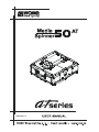
MediaSpinner 50 AT
Table of contents
1. Safety instructions ......................................................................................................... 3
2.Operating determinations............................................................................................... 4
3. Description of the device............................................................................................... 5
4. Installation....................................................................................................................... 6
4.1 Connection to the mains ............................................................................................ 6
4.2 Changing the power supply settings .......................................................................... 6
4.3 Rigging the fixture ...................................................................................................... 7
4.4 DMX-512 connection/connection between fixtures .................................................... 9
5. MediaSpinner 50 AT- DMX Protocol-version 1.0 ....................................................... 10
6. Operating modes ......................................................................................................... 11
6.1 Controller mode........................................................................................................ 11
6.2 Stand-alone mode.................................................................................................... 11
7.Control menu map......................................................................................................... 12
8. Control menu ............................................................................................................... 14
8.1 Fixture Address ....................................................................................................... 14
8.2 Slave control ........................................................................................................... 14
8.3 Fixture informations.................................................................................................. 14
8.4 Personality ............................................................................................................... 15
8.5 Load On/Off ............................................................................................................. 16
8.6 Manual mode ........................................................................................................... 16
8.7 Test sequences........................................................................................................ 17
8.8 Stand-alone setting ................................................................................................. 17
8.9 Reset function .......................................................................................................... 18
8.10 Special functions .................................................................................................... 18
9. Low power mode .......................................................................................................... 18
10. Error and information messages .............................................................................. 19
11. Technical specifications ............................................................................................ 19
12. Maintenance and cleaning......................................................................................... 20
2
CAUTION!
Keep this device away from rain and moisture!
Unplug mains lead before opening the housing!
FOR YOUR OWN SAFETY, PLEASE READ THIS USER MANUAL CAREFULLY
BEFORE YOU INITIAL START - UP!
1. Safety instructions
Every person involved with installation and maintenance of this device have to:
- be qualilfied
- follow the instructions of this manual
CAUTION!
Be careful with your operations.
With a high voltage you can suffer
a dangerous electric shock when touching the wires!
This device has left our premises in absolutely perfect condition. In order to maintain this condition and to ensure a safe operation, it is absolutely necessary for the user to follow the safety instructions and warning notes
written in this manual.
Important:
The manufacturer will not accept liability for any resulting damages caused by the non-observance of this
manual or any unauthorized modification to the device.
Please consider that damages caused by manual modifications to the device are not subject to warranty.
Never let the power-cord come into contact with other cables! Handle the power cord and all connections with
the mains with particular caution!
Make sure that the available voltage is not higher than stated on the rear panel.
Always plug in the power plug least. Make sure that the power-switch is set to Off-position before you connect
the device to the mains. The power plug has to be accessable after installing the device.
Make sure that the power-cord is never crimped or damaged by sharp edges. Check the device and the powercord from time to time.
Always disconnect from the mains, when the device is not in use or before cleaning it. Only handle the powercord by the plug. Never pull out the plug by tugging the power cord.
This device falls under protection class I. Therefore it is essential to connect the yellow/green conductor to
earth.
The electric connection, repairs and servicing must be carried out by a qualified employee.
Do not connect this device to a dimmer pack.
During the initial start-up some smell may arise. This is a normal process and does not necessarily mean that
the device is defective.
3
2.Operating determinations
This device was designed for indoor use only.
If the device has been exposed to drastic temperature fluctuation (e.g. after transportation), do not switch it on
immediately. The arising condensation water might damage your device. Leave the device switched off until
it has reached room temperature.
Do not shake the device. Avoid brute force when installing or operating the device.
Always hold the device at the transport handles.
When choosing the installation-spot, please make sure that the device is not exposed to extreme heat, moisture
or dust. There should not be any cables lying around. You endanger your own and the safety of others!
Make sure that the area below the installation place is blocked when rigging, derigging or servicing the fixture.
Always fix the fixture with an appropriate safety rope. Fix the safety rope at the correct holes only.
Only operate the fixture after having checked that the housing is firmly closed and all screws are tightly fastened.
The maximum ambient temperature 40°C must never be exceeded.
Operate the device only after having familiarized with its functions. Do not permit operation by persons not
qualified for operating the device. Most damages are the result of unprofessional operation!
CAUTION!
The maximum load of the device is 50 kg !
Please use the original packaging if the device is to be transported.
Please consider that unauthorized modifications on the device are forbidden due to safety reasons!
If this device will be operated in any way different to the one described in this manual, the product may suffer
damages and the guarantee becomes void.
4
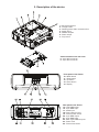
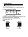
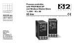
3. Description of the device
1- Quick-lock fastener
2 - Omega holder
3 - Rotating plate+video connection box
4 - Audio output
5 - RGBHV outputs
6 - Power output
7 - Top covers
Video connection box-rear side:
8 - 3-pin XLR connector
9 - 5-pin XLR connector
Front panel of the fixture:
10 - Mode-button
11 - Enter-button
12 - Up-button
13 - Down-button
14 - Display
Rear panel of the fixture
15- 5-pin DMX output
16 - 5-pin DMX input
17 - Audio input
18- Fuse holder for load
19 - Fixture power switch
20 - 3-pin DMX output
21 - 3-pin DMX input
22 - BNC Type RGBHV inputs
23 - Power cord
24 - Fixture fuse holder
5
4. Installation
4.1 Connection to the mains
Verify the power supply settings before applying power!
If you wish to change the power supply settings,see the chapter below.
Connect the fixture to the mains with the power cord.
If the plug on the flexible cord is not the right type for your socket outlets,do not use an adaptor,but remove the
plug from the cord and discard.Carefully prepare the end of the the supply cord and fit a suitable plug.
The earth has to be connected!
The occupation of the connection-cables is as follows:
Cable (EU)
Cable (US)
Pin
International
Brown
Black
Live
L
Light blue
White
Neutral
N
Yellow/Green
Green
Earth
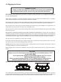
4.2 Changing the power supply settings
The transformer must be connected correctly for the local AC voltage.
The wrong settings can cause poor performance or demage of the MediaSpinner 50 AT . The factory settings
are printed next to the power cord.
If you want to change the power supply settings, follow the instructions:
1. Disconnect the fixture from AC power.
2. Remove the top base cover (closest to the power cord) by loosening the 9 screws.
3. Move the wire 1 on the transformer connection block to the position according to the desired voltage.
5. Close the base before applying AC power.
Examples:
EU-version:
US-version:
AC 230V/50Hz
AC 120V/60Hz
6
4.3 Rigging the fixture
DANGER TO LIFE!
Please consider the respective national norms during the installation!
The installation must only be carried out by an authorized distributor.
The installation must always be secured with a secondary safety attachment, e.g. an appropriate catch net.
This secondary safety attachment must be constructed in a way that no part of the installation can fall down if
the main attachment fails.
When rigging, derigging or servicing the fixture staying in the area below the installation place, on bridges,
under high working places and other endangered areas is forbidden.
The operator has to make sure that safety-relating and machine-technical installations are approved by an expert
before taking into operation for the first time and after changes before taking into operation another time.
The operator has to make sure that safety-relating and machine-technical installations are approved by an
expert after every four year in the course of an acceptance test.
The operator has to make sure that safety-relating and machine-technical installations are approved by a skilled
person once a year.
IMPORTANT! OVERHEAD RIGGING REQUIRES EXTENSIVE EXPERIENCE, including (but not limited to)
calculating working load limits, installation material being used, and periodic safety inspection of all installation
material and the device. If you lack these qualifications, do not attempt the installation yourself, but instead use
a professional structural rigger. Improper installation can result in bodily injury and.or damage to property.
The device has to be installed out of the reach of people.
If the device shall be lowered from the ceiling or high joists, professional trussing systems have to be used.
The device must never be fixed swinging freely in the room.
Caution: Devices may cause severe injuries when crashing down! If you have doubts concerning the safety of
a possible installation, do NOT install the device!
Before rigging make sure that the installation area can hold a minimum point load of 10 times the device’s
weight.
CAUTION !
Alvays secure the fixed object to the rotating plate of the Media Spinner 50 AT
by the safety cable.
Use 2 appropriate clamps to rig the Media Spinner 50 AT on a truss.
Maximum load of the fixture is 50 kg.
Make sure that the Media Spinner 50 AT is fixed properly! Ensure that the
structure (truss)to which you are attaching the fixtures is secure.
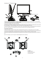
The device can be placed only in 2 positions:horizontally on a plain surface or upside down on a truss:
For overhead use, always install a safety-rope that can hold at least 10 times the weight of the device. You must
only use safety-ropes with screw-on carabines. Pull the safety-rope through the two apertures on the bottom of
the base and over the trussing system etc. Insert the end in the carabine and tighten the fixation screw.
7
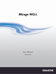
Installing the LCD display holder:
.
Detail-rotating plate:
1.Bolt two clamps (1) to the omega holders (4) with M12 bolts and lock nuts through the hole in the holders.
Note:Clamps are parts of the LCD display holder.
2.Fasten the omega holders into the rotating plate (5) by inserting both quick-lock fasteners (3) into the holes
in the plate and tighten them fully clockwise.
3.Fasten the LCD display holder (6) with installed a LCD display (9) into clamps (1).Instructions how to install
the LCD display on the LCD display holder is included in the LCD display holder set.
4.Fasten the safety cable (2) through the aperture in the LCD display holder (7) and through the two apertures
(8) in the rotating plate.The holds (10) are reserved for fixing of the LCD display lead-wires.
Overhead installation:
1.Bolt each clamp (1) to the omega holder (4) with M12 bolt and lock nut through the hole in the holder.
2.Fasten the omega holders on the bottom of the base by inserting both quick-lock fasteners (3) into the holes
of the base and tighten fully clockwise.Fasten the fixture by means of clamps a trussing system.
3.Fasten the safety cable (2) through the two apertures on the bottom of the base and over the trussing system.
Note: The clamps (1) are not a part of the MediaSpiner 50 AT delivery.
1-Clamp
2-Safety cable
3-Quick-lock fastener
4-Omega holder
8
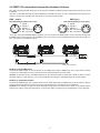
4.4 DMX-512 connection/connection between fixtures
The fixture is equipped with both 3-pin and 5-pin XLR sockets for DMX input and output.The sockets are wired
in parallel.
Only use a shielded twisted-pair cable designed for RS-485 and 3-pin or 5-pin XLR-plugs and connectors in
order to connect the controller with the fixture or one fixture with another.
DMX - output
DMX-input
XLR mounting-sockets (rear view):
XLR mounting-plugs (rear view):
1 - Shield
2 - Signal (-)
3 - Signal (+)
4 - Not connected
5 - Not connected
1 - Shield
2 - Signal (-)
3 - Signal (+)
4 - Not connected
5 - Not connected
If you are using the standard DMX controllers, you can connect the DMX output of the controller directly with
the DMX input of the first fixture in the DMX-chain. If you wish to connect DMX-controllers with other XLR-outputs, you need to use adapter-cables.
Controller operation
Master/slave operation
Building a serial DMX-chain:
Connect the DMX-output of the first fixture in the DMX-chain with the DMX-input of the next fixture. Always
connect one output with the input of the next fixture until all fixtures are connected.
Caution: At the last fixture, the DMX-cable has to be terminated with a terminator. Solder a 120 Ω resistor
between Signal (–) and Signal (+) into a 3-pin XLR-plug and plug it in the DMX-output of the last fixture.
Building a master/slave-chain:
Connect the DMX-output of the master fixture in the data-chain with the DMX-input of the first slave. Always
connect output with the input of the next slave until all slaves are connected (up to 9 fixtures).
Caution:It’s necessary to insert the XLR termination plug (with 120 Ohm) into the input of the master fixture
and into the output of the last slave fixture in the link in order to ensure proper transmission on the data link.
9
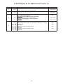
5. MediaSpinner 50 AT- DMX Protocol-version 1.0
Channel
Value
1
0 - 255
Pan coarse
Coarse control of pan movement by 450°
proportional
2
0 - 255
Pan Fine
Fine control of pan movement
proportional
0
3
1 - 255
1 - 255
4
0 - 129
130 - 139
140 - 208
210 - 219
220 - 229
230 - 239
240 - 255
Function
Pan speed
Max. speed (tracking mode)
Type of control
step
Pan speed-set Speed Mode in menu: Pan Mode
Speed from max. to min. (vector mode)
proportional
Time from 0.1 s to 25.5 s.
proportional
Pan time - set Time Mode in menu: Pan Mode
Special functions
Standard operation (fixture is controlled by channels 1, 2 and 3)
Reset of pan
Reserved
Switching On power supply of load
Reserved
Switching Off power supply of load
Reserved
10
step
step
step
step
6. Operating modes
6.1 Controller mode
The fixtures are individually addressed on a data link and connected to the controller.The fixtures respond to
the DMX signal from the controller.
The control panel on the front panel of the fixture allows you to assign the DMX fixture address, which is defined
as the first channel from which the MediaSpinner 50 AT will respond to the controller.
If you set, for example, the address to channel 5, the MediaSpinner 50 AT will use the channel 4 to 8 for control.
Please, be sure that you don’t have any overlapping channels in order to control each MediaSpinner 50 AT
correctly and independently from any other fixture on the DMX data link.
If two, three or more MediaSpinner 50 AT are addressed similarly, they will work similarly.
For address setting, please refer to the instructions under "Addressing"(menu "A001").
After having addressed all MediaSpinners 50 AT , you may now start operating these via your DMX controller.
Note:After switching on, the MediaSpinner 50 AT will automatically detect whether DMX 512 data is received
or not.If there is no data received at the DMX-input, the display will start to flash "A001" with actually set address.
This situation can occur if:
- the 3 PIN (5pin) XLR plug (cable with DMX signal from controller) is not connected with the input of the MediaSpinner 50 AT
- the controller is switched off or defective, the cable or connector is defective or the signal wires are swap in
the input connector.
6.2 Stand-alone mode
The fixtures on a data link are not connected to the controller but can execute pre-set programs which can be
different for every fixture.To set the program to be played,see the "Stand-alone setting" ( menu "St.AL.").
"Stand-alone operation" can be applied to the single fixture (the fixture may be set to the master /slave mode
or controller mode ) or to multiple fixtures operating synchronously.
Synchronous operation of multiple fixtures requires that they must be connected on a data link and one of them
is set as a master (master mode) and the rest as the slaves (slave mode).The slaves are assigned to SLA1SLA9 and on the certain slave address can be connected only one fixture.To set the fixture as the master or
slave , see the "Addressing" (menu "A001").Only one fixture can be set as the master.
If the master fixture runs a reset,all slaves will execute these acts too.
The master fixture starts simultaneous program start in the other slave fixtures.All fixtures have a definite, synchronized starting point when playing back their programs.The number of running program is the same in all
slaves and depends on the master's choice (menu "St.AL." ).Every fixture runs its program repeatedly ,starting
the program step No.1 when requested by the master .
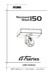
For example:
If the slave fixture has a shorter program length, it will continously repeat its program until the master fixture
finishes its own program and restarts its program running (slave 1- prog.step 3 will not be finished).
If the slave fixture has a longer program length, it will restart at prog. step 1 before it completes all its
prog.steps
(slave 2 - prog.step 5 will not be played)- see the picture bellow.
Restart
Starting point
Note:Disconect the fixtures from the DMX controller before master/slave operating ,otherwise data collisions
can occur and the fixtures will not work properly!
11
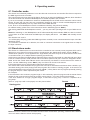
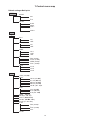
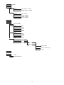
7.Control menu map
Default settings=Bold print
A001
dM.Ad.
MA.SL.
001
:
512
d.AbL
MASt.
SLA.1
:
SLA.9
SL.Ct.
InFo
Po.ti.
LA.ti.
tEMP.
DM.In.
VErS.
PErS.
r.PAn (On,Off)
LA.Pr.
dISP.
totl
rSEt
totl
rSEt
Cur.t.
Hi.tE.
rSEt
PAn (0-255)
F.PAn (0-255)
SPEd (0-255)
Func. (0-255)
IC1.b.
IC2.b.
IC3.b.
LA.Au.(On,Off)
d.L.OF.(On,Off)
dM.On (On,Off)
dM.OF.(On,Off)
LA.dE. (0..1..90)s
turn (On,Off)
d.On (On,Off)
d.Int.(20...100)
FEEd. (On,Off)
MI.SE(1...10...20)
FAn.S. (Auto,HIGH)
PA.Mo. (SP.Mo.,ti.Mo.)
ACCE (0...16...255)
In.Po.
PAn (0-255)
:
Func.(0-255)
Stor.
dF.SE.
12
LAMP
MAn.M.
(On,Off)
PrE.C.
MAn.C.
Pan (Pan.1...Pan3)
SPEd (SPd.1...SPd.5)
Pan (0-255)
F.PAn (0-255)
SPEd (0-255)
Func. (0-255)
tESt
St.AL.
Audi.(On,Off)
Auto
PLAY
Edit
Off
tESt
PrG.1
PrG.2
PrG.3
tESt
PrG.1
PrG.2
PrG.3
PrG.1
PrG.2
PrG.3
St.01
:
St.99
rESE.
SPEC.
CodE
uPd.M.(No,Yes)
13
Pan (0-255)
:
S.tim.(0.1-25.5) (s)
COPY
8. Control menu
The control panel situated on the front panel of the base offers several features. You can simply set the DMX
address,read the number of unit hours, run test, make a reset and also use many functions for setting fixture
behaviour.
Control elements on the control board:
[MODE] button-leaves menu without saving changes.
[ENTER] button- enters menu,confirms adjusted values and leaves menu.
[UP] button and[DOWN] button- moves between menu items on the the same level, sets values.
After switching the fixture on,the display shows the initial screen:
Use [UP],[DOWN] to browse through the menu. To select a function or submenu,press [ENTER].
8.1 Fixture Address
Use this menu to set the DMX address of the fixture or set the fixture as a Master (Slave).
dM.Ad. --- DMX addressing.Select this submenu to set DMX start address.
MA.SL. --- Master/slave addressing.Select this submenu to set the fixture as a Master or Slave (Slave1Slave 9).Option "d.AbL" deactivates master/slave setting.
8.2 Slave control
This function allows you to control the slaves from the master's control panel in a master/slave operation.
Select this function from the main menu and press [ENTER].Browse the list of all connected slaves ("SL.C.1"
- "SL.C.9") by pressing [UP] or [DOWN].Select the desired slave and press [ENTER]-button.The matching slave
control panel is available from the master control panel.
Note:This function is available from the master fixture only.
8.3 Fixture informations
Use this menu to read an useful information about the fixture.
Po.ti. ---Power on time.Select this submenu to read the number of operation hours of the MediaSpinner 50
AT.
totL --- The function shows the total number of the operation hours since the MediaSpinner
50 AT has been fabricated.
rSEt --- The function shows the number of the operation hours that the MediaSpinner 50 AT
has been powered on since the counter was last reset.In order to reset
this counter to 0 you have to hold [UP] and[DOWN ] and press the [ENTER].
La.ti. --- Lamp on time.Select this submenu to read the number of the operation hours of the switched on
load (e.g.projector).
totL --- The function shows the total number of the operation hours of the switched on load
14
since the MediaSpinner 50 AT has been fabricated.
rSEt --- The function shows the number of the switched on load since the counter was last
reset.In order to reset this counter to 0 you have to hold [UP] and[DOWN ] and
press [ENTER].
Cur.t. --- Current fixture temperature.
Current temperature on the main board in the base of the MediaSpinner 50 AT .
If the temperature exceeds 66°C,the fixture will go to the "Power down" mode.
Hi.tE. --- Maximum fixture temperature.
The function shows the max.temperature on the main board since
the MediaSpinner 50 AT has been fabricated.
rSEt --- Maximum resetable temperature.
The function shows the maximum temperature on the main board
since the counter was last reset.In order to reset the counter to 0 you have
to hold [UP] and[DOWN ] and press the [ENTER].
DM.In.--- Readout of DMX values.Select this function to read DMX values (0-255) of each channel received
by the fixture.
PAn
a coarse pan movement
F.PAn a fine pan movement
SPEd a pan speed
Func Special functions
VErS. --- Software version.Select this function to read the software version of processors:
IC1.b.--- Main processor on the main board in the fixture base
IC2.b.--- Pan processor on the main board in the fixture base
IC3.b. --- EEprom on the main board in the fixture base
8.4 Personality
Use this menu to to modify the MediaSpinner 50 AToperating behavior.
r.PAn --- Pan reverse.Select this function to invert the pan movement.
LA.Pr. --- Lamp presetting.Select this menu to change the "behaviour" of power supply of the load .
LA.Au. --- Select this function to switch on the the load automatically after switching on
the MediaSpinner 50 AT.
d.L.OF. --- Select this function to switch off the load via DMX.
dM.On --- This function allows you to switch on the load automatically after 26 seconds if
DMX signal is present on the data link.
dM.OF. --- This function allows you to switch Off the load automatically after 2 minutes if
DMX signal is missing on the data link.
LA.dE. --- Load power supply delay.This function allows you to set the time delay ( 0-90s)
before the load will be switched on.This setting will not affect switching the load
on direct from the control panel(menu "Lamp On/Off").
DiSP. --- Display adjusting.This function allows you to change the display settings.
turn --- Select this function to turn the display by 180°.
d.On --- This function allows you to keep the display on or to turn off automatically 2 minutes
after last pressing any button on the control panel.
d.Int. --- Select this function to adjust the display intensity (20-min.,100-max.).
bL.Co. --- Blackout during movement correction.Select this function to enable the blackout during the
head movement correction (if the moving head lost its right pan/tilt position for a short moment).
FEEd --- Pan feedback.This function allows to return the moving plate to the required pan position after changing the position by external force (e.g.by stroke).
15
Be careful, the Pan Feedback OFF is not the standard operation and the fixture can be demaged!
Note: If the feedback was switched off ,the pan-position is changed by an external force and the feedback is
switched on again,the fixture might not to be synchronized with the DMX signal.You have to make a reset in
order to synchronize the fixture with the DMX signal.
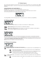
Mi.SE. --- Microphone sensitivity.Select this function to adjust the microphone sensitivity from 1(maximum) to
20(minimum).If the sensitivity is correctly adjusted,the upper segment of the first digit blinks in the bass beat.
Examples:
underexited
right level
overexited
(upper segment blinks via a bass rhythm)
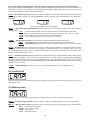
Fan.S. --- Fan speed operating modes.By using this function you can choose 2 types of the fan speed operating modes.
Auto --- The fan automatically raises its speed in order to control inside temperature
of the fixture, if the temperature inside increases about certain level.This cycle can repeat
several times until the temperature inside is on a suitable level.
HIGH --- The cooling fan works on max. speed (max. cooling).
PA.Mo. --- Pan movement mode.Use this menu to set the character of the pan movement.
ti.Mo. --- Time mode.The pan will pass its track in time that is set on the channel 3.
SP.Mo. --- Speed mode.The pan will pass its track with the speed that is set on the channel 3
ACCE --- Acceleration.Select this function in order to change the accelaration of the pan movement (0-min.
,255- max.).Default value is 16 and this value matches load about 50 kg.If you use lighter load,you can set
value greather than 16. If you want to change the acceleration of the pan movement,the pan has to be in static
position to take this change in action.
In.Po. --- Init effect positions.Select this function to adjust all effects to the desired initial positions.After switching the fixture on (if DMX is not connected),all effects will move to initial positions. Use the [UP] and [DOWN]
buttons to select desired channel and press [ENTER].Set the effect to the desired position using [UP] and
[DOWN] buttons and confirm by pressing [ENTER].After having adjusted required effects,select "Stor." to save
all values to the memory.
dF.SE. --- Default Settings .Select this option to set all fixture personalities to the default values.
8.5 Load On/Off
Use this option in order to switch on/off the power supply for load.The maximum current for load is 10 A.Do not
exceed this value.
8.6 Manual mode
Select this menu to call up presetted positions of channel effects or direct control channel effects.
PrE.C. --- Presetted effect control.Select this menu to call up presetted positions of the channel effects.
Man.C. --- Manual effect control.Select this menu to control effects by control buttoms on the control board.
PAn
a coarse pan movement
F.PAn a fine pan movement
SPEd a pan speed
Func. Special functions
16
8.7 Test sequences
Use this menu to to run a special demo-test sequences without an external controller, which will show you some
possibilities of using MediaSpinner 50 AT.
8.8 Stand-alone setting
Use this menu to set options for stand-alone mode as a selection of the playing program,programming and
modifying current programs.
Audi --- Music trigger.Select this function to enable the sound control of the running programs via the built-in
microphone.
Auto --- Presetting playback.This function allows you to select the program which will be played in the standalone mode
after switching the fixture on.Selected program will be played continuously in a loop.
d.Abl --- The option disables "Auto" function.
tESt --- The option will start built-in test program.
PrG. 1 --- The option will start created program No.1
PrG. 2 --- The option will start created program No. 2
PrG. 3 --- The option will start created program No. 3
Note:If the fixture operates in the controller mode ( DMX controller is connected) and any program from this
menu is selected ,in this case the fixture will not respond to the DMX controller after switching on and will play
selected program.
PLAY --- Playing program.Select this menu to run a bilt-in program or the 3 freely-programmable programs
in a loop.
tESt --- The option starts built-in test program.
PrG.1 --- The option starts created program No. 1
PrG.2 --- The option starts created program No. 2
PrG.3 ---The option starts created program No. 3
Select the program you wish and press [ENTER].The selected program starts running.By pressing [ENTER]
is possible to pause the program running.
Edit --- Editing program.Select this menu to edit or create the program.The MediaSpinner 50 AThas one
built-in program (test) and the 3 free programs,each up to 99 steps.Each program step has a step time.Step
time-the time,during which effects last in the current step.
If the fixture is set as a master ,then you may edit any program in the slaves.You can't edit programs on the
slave fixtures from their control panels if the master fixture is switched on and connected to the slaves (editing
is possible from the master control panel only).
Procedure:
1. Press [UP] or [DOWN] to select the program you want to edit ("PrG.1" - "PrG.3") and press [ENTER].
2. Press [UP] or [DOWN] to select the desired fixture ("MASt." - "SLA.9") and press [ENTER]-button.
3. Press [UP] or [DOWN] to select the desired program step ("St.01" - "St.99") and press [ENTER]-button.
4 Press [UP] or [DOWN] to select the desired item and press [ENTER]-button.Now you can edit by [UP] or
[DOWN] buttons the DMX value (0-255) for selected item:
P.End. - a total number of the program steps (value 1-99).This value you must set before start
programming(e.g. if you want to create program with the 10 steps,set P.End=10).
PAn
a coarse pan movement
SpEd a pan speed
Func. special functions
S.tim. a step time,value 0,1-25,5 seconds
COPY. - copying the current prog. step to the next prog. step .If the last prog.step is copied to the
next prog. step ,parameter "P.End" is increased about one automatically (except step 99).
5. Press [ENTER]-button to confirm adjusted value .
6. Press [MODE]-button,select next prog. step and repeat this procedure (steps 4 - 6).
17
8.9 Reset function
This option enables the MediaSpinner 50 AT to index all effects (functions) and return to their standard positions.
8.10 Special functions
Use this menu for special services:
CodE --- Code.This function contains identification hexadecimal code (0000-FFFF) for the fixture, which is
used for the master/slave operation.
uPd.M. ---Updating mode.Using this function you can update software in the fixture via PC and serial link.
The following are required in order to update software:
- PC running Windows 95/98/2000/XP or Linux
- DMX Software Uploader
- Flash cable RS232/DMX (No.13050624)
Note1:Software update should execute a qualified person.If you lack qualification, do not attempt the update
yourself and ask for help your ROBE distributor.
Note 2:DMX address, IP address ,programs 1-3 and all functions in menu "PErS" will be set to their default
values.
To update software in the fixture:
1.Installation of DMX Software Uploader.
1.DMX Software Uploader program is available from the ROBE web site at WWW.robe.cz.
2.Make a new directory ( e.g. Robe_Uploader) on your hard disk and download the software to it.
3.Unpack the program from the archive. If the Robe fixture is produced in magnetic and electronic
ballast version, name of DMX Software Uploader is the same for both versions.
2.Fixture software updating.
1.Determine which of your COM port is available on your PC and connect it with to the DMX input
of the fixture using the uploading cable. Do not extend this cable! Disconnect the fixture from the
other fixtures in DMX chain! Turn on the computer and the fixture.
2.Switch the fixture to the update mode by selecting the option Updating mode in menu Special
Functions on the fixture control panel:SPEC-->UPd-->yES.(From this option you cannot return back
to the main menu. If you do not want to continue in software update, you have to switch off and on
the fixture to leave this option!)
3.It is recommended that you exit all programs before running the Software Uploader.
4.Start the Software Uploader program. Select desired COM and then click Connect button.
If the conection is OK, click Start Uploading button to start uploading. It will take several minutes to
perform software update. If the option "Incremental Update"isn´t checked ,all processors will be
updated (including processors with the same software version).
If you wish to update only later versions of processors, enable the Incremental Update check box.
Avoid interrupting the process. Update status is being displayed in the list window.
When the update is finished, the line with the text “The fixture is successfuly updated‘ will appear in
this window and the fixture will reset with the new software.
Note: In the case of interruption of the upload process (e.g. power cut), the fixture remains in the update mode
and you have to repeat the software update again.
For example: The fixture was switched off before finishing software upload. After switching the fixture on again,
the fixture is still in the update mode and the display is dark. Restart the Software Uploader program and repeat
software update from your PC.
18
9. Low power mode
This mode omits fixture reset after switching the fixture on and lowers motor powers of the fixture."Power down
mode" is useful in special cases,e.g. if the fixture is in a flight case and you want to set its DMX address without
taking it out from the case.To enter "Power down mode",press and hold [UP] and [DOWN] and at the same time
switch on the Power switch.The following message appears on the display:"P.d.Mo."
Press [ENTER] to activate "Low power mode" without fixture reset.Now you can set features and behaviour
of the fixture by using "A001" and "Pers." menu.If you want to go to the "normal operation mode",execute a
fixture reset.
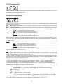
10. Error and information messages
Mb.Er.
This messsage informs you that the main PCB does not communicate correctly with the Control Board.
Fr.Er.
This message will appear if the frequency of the main is not standard 50 or 60 Hz.This message can appear as
a result of the interference during the lamp starting (if the lamp or igniter is old) or as a result of the interference
by neighbouring devices. In these cases the message does not affect the fixture operating!
Po.Er.
This message will appear if the fixture was shortly disconnect from the mains.
PA.Er. (Pan movement error)
This message will appear after the reset of the fixture if the pan plate’s magnetic-indexing circuits malfunction
(sensors failed or magnet missing) or the stepping motor is defective. (Or its driving IC on the main PCB). The
pan plate is not located in the default position after the reset.
MA.Er.(Master error)
The message informs you that the fixture was addressed as a master and DMX signal is connected to its
input.Disconnect the DMX controller from fixture's input and address the fixture as the master again.
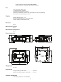
11. Technical specifications
Power supply:
EU-model:
Voltage:...........................208/230/240V AC, 50/60Hz ~
Fuse:...............................T 630mA@230V
US-model:
Voltage:...........................100/120/208/230/240V AC, 50/60Hz ~
Fuse:................................T 1.25@120V
Power consumption:.........30 VA
Fuse for load:.............................................T 10 A
Electronics:
-Addressing,special functions setting via control panel with 4-digit LED display
-Readout fixture usage,receiving DMX values,temperature, etc
-Built-in analyzer for easy fault finding,error messages
-Bilt-in demo sequences
-Silent cooling,
-Master/slave operation
-Digital serial input/output DMX-512
-4 control channels
Data input/output
base:
- 3-pin/5-pin XLR male sockets for DMX data input
- 3-pin/ 5-pin XLR female sockets for DMX data output
- 5 x BNC for RGBHV
- Audio connection (Neutrik NC3 MD-L-1)
load: Video connection RGBHV(5x BNC connector)
Audio connection ( Neutrik NC3 FD-L-1)
19
Power supply connection (Neutrik NAC3MPB)
DMX connection (3-pin/5-pin XLR female sockets)
Pan
-Pan movement range 450°
-16 bit movement resolution
-Automatic pan position correction
-Remotely controllable speed of pan movement for easy programming
-Movement control:tracking and vector
Rigging
-Stands directly on the floor
-Mounts horizontally with 2 Omega brackets
-Safety chain/cord attachment point
Max.load
50 kg
Max.current for load
10 A
Max.ambient temperature
40°C
Dimensions(mm):
Weight (net):
13.4 kg
Accessories
Omega holder No.99010420........................4 pieces
Neutrik NAC3FCB plug No.13050735..........1 piece
Optional accessories
LCD display holder set No.10980036
20
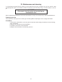
12. Maintenance and cleaning
It is absolutely essential that the fixture is kept clean.Dust must be cleaned from the fan and air vents
periodically.The interior of the fixture should be cleaned at least annually using a vacuum-cleaner or an airjet.
DANGER !
Disconnect from the mains before starting any
maintenance work
More complicated maintenance and service operations are only to be carried out by authorized distributors.
Replacing the fuse
Only replace the fuse by a fuse of same type and rating.Before replacing the fuse, unplug mains lead!
Procedure:
1) Unscrew the fuseholder on the rear panel of the base with a fitting screwdriver from the housing
(anti - clockwise).
2) Remove the old fuse from the fuseholder.
3) Install the new fuse in the fuseholder.
4) Replace the fuseholder in the housing and fix it.
21