1
SystemCORP
Embedded Technology Pty Ltd
WEBCAN Substation Control and
Monitoring System
WebCAN Designer Studio
User & Reference Manual
This PDF Document contains internal hyperlinks for ease of navigation.
For example, click on any item listed in the Table of Contents to go to that page.
WebCAN Designer Studio General Description
WebCAN Designer Studio Step-by-step User Guide
System Diagnostic User Guide
WebCAN Designer Studio Reference
Trouble Shooting
WEBCAN Substation
Control and
Monitoring System
WebCAN Designer Studio
User and Reference Manual
Copyright: All rights reserved. None of the information contained in this document may be reproduced or stored in a database
or retrieval system or disclosed to others without written authorization by SystemCORP Embedded Technology Pty Ltd.
The information in this document is subject to change without prior notice and should not be construed as a commitment by
SystemCORP Embedded Technology Pty Ltd. SystemCORP Embedded Technology Pty Ltd do not assume responsibility for
any errors, which may be in this document.
Documentation Control
Author:
Version:
Version History:
Oscar Naval
2.02
1.10 Demonstration Release
2.00 Product Release
2.01 Product reference system re-number only
2.02 Minimum system requirements, Node Descriptions, minor changes
Creation Date:
1 May 2009
Last Version Date:
7 April 2011
Product Reference:
Document Status:
WebCAN Designer Studio
User and Reference Manual
500-0002
RELEASED
Page 2 of 112
WEBCAN Substation
Control and
Monitoring System
WebCAN Designer Studio
User and Reference Manual
Table of Contents
1
Introduction..................................................................................................................9
2
Scope ........................................................................................................................10
3
Overview ...................................................................................................................11
3.1
3.2
3.3
3.4
4
Document Reference .....................................................................................................................11
List of Abbreviations .......................................................................................................................11
Motivation And Purpose .................................................................................................................12
Document Guidelines .....................................................................................................................12
General Description...................................................................................................13
4.1
4.1.1
4.2
4.2.1
4.2.2
4.3
5
CFE File Configuration ...................................................................................................................16
Location of the CFE Files...............................................................................................................16
WDS Demonstration Version .........................................................................................................17
Limitations of the Demonstration Version ......................................................................................17
Saved Demonstration Projects may be Upward Compatible .........................................................17
WebCAN Designer Studio Quick Walk-thru 3-Page Tour..............................................................18
WebCAN Designer Studio User Guide ......................................................................21
5.1
5.1.1
5.1.2
5.2
5.2.1
5.2.2
5.2.3
5.2.4
5.2.5
5.2.6
5.2.7
Security & User Administration ......................................................................................................21
SystemCORP Administrator...........................................................................................................21
User Access ...................................................................................................................................22
Assembling and Editing a WebCAN Designer Studio Project .......................................................23
Creating a New System Design with WebCAN Designer Studio...................................................24
5.2.1.1
SYSTEM Settings.......................................................................................................... 34
5.2.1.2
SYSTEM Parameters (none)......................................................................................... 34
Communications Front-End (CFE) Object .....................................................................................35
5.2.2.1
CFE Description ............................................................................................................ 35
5.2.2.2
CFE Settings ................................................................................................................. 35
5.2.2.3
CFE Parameters............................................................................................................ 36
Network (NET) Object ....................................................................................................................37
5.2.3.1
NET Description ............................................................................................................ 37
5.2.3.2
NET Settings ................................................................................................................. 37
5.2.3.3
NET Parameters (none) ................................................................................................ 37
Mini Remote Terminal Unit (RTU) Object ......................................................................................38
5.2.4.1
RTU Description ............................................................................................................ 38
5.2.4.2
RTU Settings ................................................................................................................. 38
5.2.4.3
RTU Parameters............................................................................................................ 38
CAN Application Configuration Table (CANACT) Object...............................................................39
5.2.5.1
CANACT Description..................................................................................................... 39
5.2.5.2
CANACT Settings.......................................................................................................... 39
5.2.5.3
CANACT Parameters .................................................................................................... 39
Analog Input Module (ACM) Alternating Current (AC) Object .......................................................40
5.2.6.1
ACM Description............................................................................................................ 40
5.2.6.2
ACM Settings................................................................................................................. 41
5.2.6.3
ACM Parameters ........................................................................................................... 41
Analog Input Module (AIM) Direct Current (DC) Object.................................................................42
5.2.7.1
AIM Description ............................................................................................................. 42
5.2.7.2
AIM Common Settings................................................................................................... 42
5.2.7.3
AIM Common Parameters............................................................................................. 42
5.2.7.4
AIM AI and AI TAP Channel Settings and Parameters ................................................. 43
WebCAN Designer Studio
User and Reference Manual
Page 3 of 112
WEBCAN Substation
Control and
Monitoring System
WebCAN Designer Studio
User and Reference Manual
5.2.8 Digital Input Module (DIM) Object ..................................................................................................44
5.2.8.1
DIM Description ............................................................................................................. 44
5.2.8.2
DIM Common Settings .................................................................................................. 45
5.2.8.3
DIM Common Parameters............................................................................................. 45
5.2.8.4
Digital Input Module SPI, DPI, TAP, BCD, and Counter Input Channels...................... 46
5.2.9 High Current Output Module (HCM) Object ...................................................................................53
5.2.9.1
HCM Description ........................................................................................................... 53
5.2.9.2
HCM Settings ................................................................................................................ 54
5.2.9.3
HCM Parameters........................................................................................................... 54
5.2.10 Low Current Output Module (LCM) Object ....................................................................................55
5.2.10.1 LCM Description ........................................................................................................... 55
5.2.10.2 LCM Settings ................................................................................................................ 55
5.2.10.3 LCM Parameters........................................................................................................... 56
5.2.11 Diagnostic Object ...........................................................................................................................57
5.2.11.1 Diagnostic Description .................................................................................................. 57
5.2.11.2 Diagnostic Settings ....................................................................................................... 57
5.2.11.3 Diagnostic Parameters ................................................................................................. 57
5.2.12 External Application (EXT) Object..................................................................................................58
5.2.12.1 EXT Description ............................................................................................................ 58
5.2.12.2 EXT Settings ................................................................................................................. 58
5.2.12.3 EXT Parameters ........................................................................................................... 58
5.2.13 PLC Application Configuration Table (ACT) Object .......................................................................59
5.2.13.1 PLC ACT Description.................................................................................................... 59
5.2.13.2 PLC ACT Settings......................................................................................................... 59
5.2.13.3 PLC ACT Parameters ................................................................................................... 59
5.2.14 PLC Input/Output (I/O) Object........................................................................................................60
5.2.14.1 PLC IO Description ....................................................................................................... 60
5.2.14.2 PLC IO Settings ............................................................................................................ 60
5.2.14.3 PLC IO Parameters (None) .......................................................................................... 60
5.2.15 Protocol Client / Server Objects .....................................................................................................61
5.2.15.1 Protocol Description...................................................................................................... 61
5.2.15.2 Protocol Settings........................................................................................................... 61
5.2.15.3 Protocol Parameters ..................................................................................................... 61
5.3
Compile and Download/Upload to/from the RTU, BCU, or DA RTU CFEs ...................................62
5.3.1 Compile (Design Check) ................................................................................................................62
5.3.2 Download .......................................................................................................................................63
5.3.3 Upload ............................................................................................................................................64
5.4
Print Project Report and Printing....................................................................................................65
5.4.1 Print Report ....................................................................................................................................65
5.4.2 Project Summary............................................................................................................................66
5.4.3 Communication Parameters...........................................................................................................66
5.4.4 Reference List ................................................................................................................................67
5.4.5 Device Settings ..............................................................................................................................67
5.4.6 Diagnostic Log................................................................................................................................68
5.4.7 Print Setup......................................................................................................................................70
5.4.7.1
Print Setup General ....................................................................................................... 70
5.4.7.2
Print Setup Headers/Footers......................................................................................... 71
5.4.7.3
Print Setup Margins ....................................................................................................... 72
5.4.7.4
Print Setup Preferences ................................................................................................ 73
5.4.8 Print Preview ..................................................................................................................................74
5.5
WebCAN Designer Studio Tools....................................................................................................75
5.5.1 Manage Tools.................................................................................................................................75
5.5.2 CFE Information .............................................................................................................................76
5.5.3 Ping ................................................................................................................................................76
5.5.4 Diagnostic.......................................................................................................................................76
5.5.5 OpenPCS .......................................................................................................................................76
6
System Diagnostic User Guide..................................................................................77
6.1
Diagnostic Log................................................................................................................................78
WebCAN Designer Studio
User and Reference Manual
Page 4 of 112
WEBCAN Substation
Control and
Monitoring System
WebCAN Designer Studio
User and Reference Manual
6.1.1 Global Diagnostic Log ....................................................................................................................78
6.1.1.1
Save Logfile................................................................................................................... 78
6.1.1.2
Columns in Global Diagnostic Log ................................................................................ 79
6.1.1.3
Log Filters...................................................................................................................... 80
6.2
Diagnostic Monitoring.....................................................................................................................82
6.2.1 Substitute .......................................................................................................................................82
6.2.2 Direct Drive.....................................................................................................................................83
6.2.3 Counter Operation..........................................................................................................................84
7
Reference..................................................................................................................85
7.1
Toolbar Windowpane .....................................................................................................................85
7.2
Menu Bar Menus ............................................................................................................................86
7.2.1 File Pull-down Menu.......................................................................................................................86
7.2.1.1
Import New Database.................................................................................................... 86
7.2.1.2
Export Database to EDS files........................................................................................ 86
7.2.1.3
Exit................................................................................................................................. 86
7.2.2 Edit Pull-down Menu ......................................................................................................................86
7.2.2.1
Copy .............................................................................................................................. 86
7.2.2.2
Copy Selected Reference Node(s)................................................................................ 86
7.2.2.3
Paste ............................................................................................................................. 86
7.2.2.4
Paste Selected Referece Node(s)................................................................................. 86
7.2.2.5
Fill Down........................................................................................................................ 86
7.2.3 View Pull-down Menu.....................................................................................................................87
7.2.3.1
Alert & Info Messages ................................................................................................... 87
7.2.4 Project Pull-down Menu .................................................................................................................87
7.2.4.1
Create New Project ....................................................................................................... 87
7.2.4.2
Open Project.................................................................................................................. 87
7.2.4.3
Save Project .................................................................................................................. 87
7.2.4.4
Copy Project .................................................................................................................. 87
7.2.4.5
Compile Project ............................................................................................................. 87
7.2.4.6
Download Project .......................................................................................................... 87
7.2.4.7
Print Project Report ....................................................................................................... 87
7.2.4.8
Reopen Project.............................................................................................................. 87
7.2.4.9
About Current Project .................................................................................................... 88
7.2.5 Tools Pull-down Menu....................................................................................................................88
7.2.6 User Pull-down Menu .....................................................................................................................89
7.2.6.1
User Administration ....................................................................................................... 89
7.2.6.2
Group Access Rights are NOT mutually exclusive ....................................................... 90
7.2.6.3
Logout............................................................................................................................ 91
7.2.7 Help Pull-down Menu .....................................................................................................................92
7.2.7.1
About ............................................................................................................................. 92
7.2.7.2
WebCAN Designer Help................................................................................................ 92
7.2.7.3
WebCAN Hardware Manual .......................................................................................... 92
7.2.7.4
WebCAN IEC1131 Manual............................................................................................ 92
7.2.7.5
OpenPCS Help .............................................................................................................. 92
7.3
Context Specific (Right-Mouse Click) Pop-up Menus ....................................................................93
7.3.1 Project Windowpane Pop-up Menu................................................................................................94
7.3.1.1
Add Object..................................................................................................................... 94
7.3.1.2
Delete Object................................................................................................................. 94
7.3.1.3
Copy Object................................................................................................................... 94
7.3.1.4
Paste Object .................................................................................................................. 94
7.3.1.5
Export Protocol XML...................................................................................................... 94
7.3.1.6
Run Application….......................................................................................................... 94
7.3.1.7
Import for Application… ................................................................................................. 94
7.3.1.8
Export for Application…................................................................................................. 94
7.3.1.9
Save Project .................................................................................................................. 94
7.3.1.10 Open Project ................................................................................................................. 95
7.3.1.11 New Project................................................................................................................... 95
7.3.1.12 Reboot CFE(s) .............................................................................................................. 95
WebCAN Designer Studio
User and Reference Manual
Page 5 of 112
WEBCAN Substation
Control and
Monitoring System
WebCAN Designer Studio
User and Reference Manual
7.3.1.13 CFE Logs ...................................................................................................................... 95
7.3.1.14 About Project ................................................................................................................ 95
7.3.2 Object Settings Windowpane Pop-up Menu ..................................................................................95
7.3.2.1
Edit................................................................................................................................. 96
7.3.2.2
Row................................................................................................................................ 96
7.3.2.3
Column .......................................................................................................................... 97
7.3.2.4
Object Name / Referenced by ....................................................................................... 97
7.3.2.5
Print ............................................................................................................................... 97
7.3.2.6
Table.............................................................................................................................. 98
7.3.3 Diagnostic Context Specific (Right-Mouse Click)Pop-up Menus ...................................................99
7.3.3.1
Start Diagnostic ............................................................................................................. 99
7.3.3.2
Detach Current Page................................................................................................... 100
7.3.3.3
Copy Selected Log Message ...................................................................................... 100
7.3.3.4
Show Monitoring.......................................................................................................... 100
7.3.3.5
Hide Monitoring ........................................................................................................... 100
7.3.3.6
Attach Window............................................................................................................. 100
7.3.3.7
Detach Window ........................................................................................................... 100
7.3.3.8
Serial Port Monitoring .................................................................................................. 101
7.3.3.9
Substitute..................................................................................................................... 102
7.3.3.10 Drive Output............................................................................................................... 102
7.3.3.11 Counter Operation ...................................................................................................... 102
7.4
Objects, Object Settings and Parameters ....................................................................................103
7.5
Messages and Dialog boxes ........................................................................................................104
8
Trouble Shooting .....................................................................................................105
8.1
8.2
8.2.1
8.2.2
8.2.3
8.2.4
Alert Messages.............................................................................................................................105
Issues / Solutions .........................................................................................................................109
Objects Issue / Solutions..............................................................................................................109
Compile or Download Issues / Solutions......................................................................................110
Printing and Saving Issues / Solutions.........................................................................................111
External Application (e.g. OpenPCS) Interface Issues / Solutions ..............................................112
WebCAN Designer Studio
User and Reference Manual
Page 6 of 112
WEBCAN Substation
Control and
Monitoring System
WebCAN Designer Studio
User and Reference Manual
Table of Figures
Figure 4-1 – Overview of the WebCAN Communication Front End Structure .........................................................14
Figure 4-2 – Overview or the Remote Terminal Unit (RTU) Structure.....................................................................15
Figure 4-3 – Overview of the Substation Control Structure with Bay Control Units (BCU)......................................15
Figure 4-4 – Overview of the Distribution Automation System (DAS): ....................................................................15
Figure 5-1 – Login screen for WebCAN Designer Studio ........................................................................................21
Figure 5-2 – User Administration default “Group Access Rights” settings...............................................................22
Figure 5-3 – WebCAN Designer Studio Windowpane Descriptions ........................................................................23
Figure 5-4 – Add CFE object from Object Library to Project Windowpane..............................................................35
Figure 5-5 – Add NET object from Object Library to Project Windowpane..............................................................37
Figure 5-6 – Add CFE object from Object Library to Project Windowpane..............................................................38
Figure 5-7 – Add CANACT object from Object Library to Project Windowpane......................................................39
Figure 5-8 – Add ACM object from Object Library to Project Windowpane.............................................................40
Figure 5-9 – Add AIM object from Object Library to Project Windowpane ..............................................................42
Figure 5-10 – Add DIM object from Object Library to Project Windowpane ............................................................44
Figure 5-11 – Add HCM object from Object Library to Project Windowpane...........................................................54
Figure 5-12 – Add LCM object from Object Library to Project Windowpane ...........................................................55
Figure 5-13 – Add Diagnostic object from Object Library to Project Windowpane..................................................57
Figure 5-14 – Add EXT object from Object Library to Project Windowpane............................................................58
Figure 5-15 – Add ACT object for PLC from Object Library to Project Windowpane ..............................................59
Figure 5-16 – Add I/O object for PLC from Object Library to Project Windowpane.................................................60
Figure 5-17 – Compile Dialog Box ...........................................................................................................................62
Figure 5-18 – Download project to the CFE Hardware dialog box ..........................................................................63
Figure 5-19 – Upload project from the CFE hardware dialog box ...........................................................................64
Figure 5-20 – Print Report Dialog box – Report Setup/Printing Tab........................................................................65
Figure 5-21 – Print Report Dialog box –Project Summary Tab ...............................................................................66
Figure 5-22 – Print Report Dialog box – Communications Parameters Tab............................................................66
Figure 5-23 – Print Report Dialog box – Reference List Tab...................................................................................67
Figure 5-24 – Print Report Dialog box – Report Setup/Printing Tab........................................................................67
Figure 5-25 – Print Report Dialog box – Diagnostic Tab .........................................................................................68
Figure 5-26 – Print Report Dialog box – Diagnostic Log Tab with Filters ................................................................69
Figure 5-27 – Print Setup .........................................................................................................................................70
Figure 6-1 – System Diagnostic Environment Window............................................................................................77
Figure 6-2 – Global Diagnostic Log Windowpane....................................................................................................78
Figure 6-3 – Defining Diagnostic Log Filter Example...............................................................................................80
Figure 7-1 – Toolbar Windowpane...........................................................................................................................85
Figure 7-2 – About Current Project ..........................................................................................................................88
Figure 7-3 – User Administration Group Access Rights Default Settings................................................................90
Figure 7-4 – About WebCAN Designer Studio Version Window .............................................................................92
Figure 7-5 – Context Specific (Right-mouse click) Pop-up Menus ..........................................................................93
Figure 7-6 – Project Windowpane right-click context pop-up menus.......................................................................94
Figure 7-7 – Object Settings Windowpane right-click context pop-up menus .........................................................95
Figure 7-8 – Auto Labelling Dialog Box ...................................................................................................................97
Figure 7-9 – Serial Port Monitoring ........................................................................................................................101
WebCAN Designer Studio
User and Reference Manual
Page 7 of 112
WEBCAN Substation
Control and
Monitoring System
WebCAN Designer Studio
User and Reference Manual
List of Tables
Table 4-1 – CFE A: Drive Contents and their Functions..........................................................................................16
Table 4-2 – CFE B:\APPS Folder Drive Contents and their Functions....................................................................16
Table 4-3 – CFE B:\CONFIG Folder Contents and their Functions.........................................................................16
Table 5-1 – System Settings ....................................................................................................................................34
Table 5-2 – CFE Settings.........................................................................................................................................35
Table 5-3 – CFE Parameters ...................................................................................................................................36
Table 5-4 – NET Settings.........................................................................................................................................37
Table 5-5 – RTU Settings.........................................................................................................................................38
Table 5-6 – RTU Parameters ...................................................................................................................................38
Table 5-7 – CANACT Settings .................................................................................................................................39
Table 5-8 – CANACT Parameters............................................................................................................................39
Table 5-9 – ACM Settings ........................................................................................................................................41
Table 5-10 – ACM Parameters ................................................................................................................................41
Table 5-11 – AIM Common Settings ........................................................................................................................42
Table 5-12 – AIM Common Parameters ..................................................................................................................42
Table 5-13 – AI Channel Specific Settings ..............................................................................................................43
Table 5-14 – AI TAP Channel Specific Settings ......................................................................................................43
Table 5-15 – DIM Common Settings........................................................................................................................45
Table 5-16 – DIM Common Parameters ..................................................................................................................45
Table 5-17 – DIM SPI Specific Settings ...................................................................................................................46
Table 5-18 – DIM SPI Specific Parameters .............................................................................................................47
Table 5-19 – DIM DPI Specific Settings...................................................................................................................48
Table 5-20 – DIM TAP Specific Settings..................................................................................................................49
Table 5-21 – DIM TAP Specific Parameters ............................................................................................................49
Table 5-22 – DIM BCD Specific Settings .................................................................................................................50
Table 5-23 – DIM BCD 7-Segment Display Truth Table..........................................................................................51
Table 5-24 – DIM Counter Specific Settings............................................................................................................52
Table 5-25 – HCM Settings......................................................................................................................................54
Table 5-26 – HCM Parameters ................................................................................................................................54
Table 5-27 – LCM Settings ......................................................................................................................................55
Table 5-28 – LCM Parameters.................................................................................................................................56
Table 5-29 – Diagnostic Object Settings..................................................................................................................57
Table 5-30 – Diagnostic Object Parameters ............................................................................................................57
Table 5-31 – EXT Settings .......................................................................................................................................58
Table 5-32 – EXT Parameters .................................................................................................................................58
Table 5-33 – PLCACT Settings................................................................................................................................59
Table 5-34 – PLCACT Parameters ..........................................................................................................................59
Table 5-35 – PLC IO Settings ..................................................................................................................................60
Table 5-36 – Protocol Settings.................................................................................................................................61
Table 6-1 – Columns in Global Diagnostic Log........................................................................................................79
Table 6-2 – Global Diagnostic Log Status Descriptions...........................................................................................79
Table 7-1 – User Administration “Group Access Rights” Keyword Descriptions .....................................................91
Table 8-1 – Alert Messages, Description, and Suggested Solutions.....................................................................105
WebCAN Designer Studio
User and Reference Manual
Page 8 of 112
WEBCAN Substation
Control and
Monitoring System
WebCAN Designer Studio
User and Reference Manual
Introduction
1 Introduction
WebCAN Designer is Windows® based software used for configuration, diagnostics and
troubleshooting of a WebCAN Substation Control and Monitoring System. Configurable properties of
system modules are specified in individual Electronic Data Sheets (EDS). Each system module is
represented as an object. With a simple drag and drop mechanism, a complex control system can
easily and quickly be created and configured. During the configuration process, all values and settings
are automatically passed through a consistency and error check to provide system integrity.
Furthermore, each object added or removed is recorded in the system log for future reference.
Moving away from the traditional serial port configuration, WebCAN Designer uses a much faster
communication medium, fast Ethernet. With the support of Ethernet, WebCAN Designer can administer
the substation control systems remotely without being physically in the substation. Furthermore,
WebCAN Designer pioneered the substation configuration and diagnostics with USB connection as an
alternative to the standard Ethernet link.
The WebCAN Designer not only configures the substation control system, but also provides logging of
system activities, diagnostic of system status and substitutions of field IO channels.
In a substation control system, security is a fundamental concern. The WebCAN Designer integrates
user profiles for different groups according to technical competence and access rights. Tasks and
actions performed by individual users are logged for review and audit purposes. In addition, the
WebCAN Designer projects are compressed and encrypted to prevent unauthorized modifications.
Minimum System Requirements:
Operating system
Processor
System Memory
Graphics
Hard disk space
Input device
Microsoft Windows® System XP, Service Pack 2 or higher
Windows 2000 not supported
Intel Core 2 Duo® 1.8 GHz or AMD AM2 x2 3800+
1024 MB or more
1280x1024 resolution
5 GB
Keyboard+Two-button scroll-wheel mouse
Communication:
10/100 Ethernet connection
Rs232 serial port
Optional USB port
WebCAN Designer Studio
User and Reference Manual
Page 9 of 112
WEBCAN Substation
Control and
Monitoring System
WebCAN Designer Studio
User and Reference Manual
Scope
2 Scope
This document is divided into the following major sections:
General Description that includes file descriptions and a Quick Walk-thru 3-Page Tour
WebCAN Designer Studio Step-by-step including Creating a New System Design and an object (the
software model of the hardware modules) detailed description
System Diagnostics
Reference Section – Item by item toolbar icon, pull-down menu, and right-mouse click pop-up menu item
Trouble Shooting – including an Alert Message list
Specific Client and Server protocols are beyond the scope of this document. For DNP3, GPRS Gateway, IEC
61850 and others see the appropriate documents.
For hardware configuration and other applications used with WebCAN Designer Studio see the appropriate
documents listed on the following page.
WebCAN Designer Studio
User and Reference Manual
Page 10 of 112
WEBCAN Substation
Control and
Monitoring System
WebCAN Designer Studio
User and Reference Manual
Overview
3 Overview
3.1 Document Reference
[1]
Document Title:
Revision:
Source:
IEC61131 PLC User Manual
Version 1.00 English
SystemCORP Embedded Technology Pty Ltd
[2]
Document Title:
Revision:
Source:
Infoteam OpenPCS Programming System
Version 4.1 English
InfoTeam
Document Title:
Revision:
Source:
Hardware Description and User Manual
Version 1.0 English
SystemCORP Embedded Technology Pty Ltd
[3]
These documents are available on the
“Help” pull-down menu.
3.2 List of Abbreviations
ACM
=
Alternate Current Measurement Module
ACT
=
Application Configuration Table
AIM
=
Analogue Input Module
AVA
=
Automatic Voltage Adjust
BCD
=
Binary Coded Decimal
BCU
=
Bay Control Unit
CAN
=
Controller Area Network
CFE
=
Communications Front End
DA
=
Distribution Automation
DDI
=
Double Digital Input
DI
=
Digital Input
DIM
=
Digital Input module
FTP
=
File Transfer Protocol
HCM
=
High Current digital output Module
I/O
=
Input/Output
LCM
=
Low Current digital output Module
ORT
=
Object Reference Table
PLC
=
Programmable Logic Controller
RTU
=
Remote Terminal Unit
SCADA =
Supervisory Control and Data Acquisition
SDI
=
Single Digital Input
SOE
=
Sequence of Events
SCS
=
Substation Control System
WebCAN Designer Studio
User and Reference Manual
Page 11 of 112
WEBCAN Substation
Control and
Monitoring System
WebCAN Designer Studio
User and Reference Manual
Overview
3.3 Motivation And Purpose
WebCAN Designer is a robust and flexible package for easy system configuration of the WebCAN Substation
control and monitoring system.
The CFE communication frontend processors of the WebCAN system contain the distributed database of the
WebCAN Substation control and monitoring system, which provide support for protocol conversion, event
handling and processes control.
The database requires the information of all configured data points in order to correctly and efficiently route the
information
The purpose of this document is to allow any user to configure the package and to design, download and test the
WebCAN Substation control and monitoring system as required for their application.
3.4 Document Guidelines
The intended audience for this document are the Users of a WEBCAN Designer who engineer and design the
Substation control and monitoring system. It aims at assisting them in setting up and configuring the base
software as well as testing and diagnose the designated system.
An understanding of the hardware (refer to [3] Hardware Description and User Manual) is a requirement when
using the WEBCAN Designer software.
WebCAN Designer Studio
User and Reference Manual
Page 12 of 112
WEBCAN Substation
Control and
Monitoring System
WebCAN Designer Studio
User and Reference Manual
General Description
4 General Description
The WebCAN Substation Control and Monitoring System hardware (for details refer to [3]) can easily be setup in
the user friendly “WebCAN Designer Studio” configuration application. This user manual explains setting up
software applications for the WebCAN Substation Control and Monitoring system.
The main tasks of a substation control system or of a simple Remote Terminal Unit (RTU), involve data
acquisition of substation data, providing data for fault recording and power quality. Modern systems also provide
local substation automation functionality and protection integration. Therefore, the configuration of such systems
is a mission critical task where mistakes might result in major failures in an electrical grid. The traditional way of
configuring the system is to use text editors to write the configuration script before it is downloaded to the system.
This method not only involves many manual operation steps, such as writing the scripts, encoding the files and
downloading the configurations into the controller, but also prone to have errors due to lack of automated error
checking and validation mechanism. For this reason, WebCAN Designer Studio is required for a state of the art
substation control system.
WebCAN Designer Studio software provides a GUI (Graphic User Interface) driven design platform that directly
communicates to the system to configure. This method gives the designers the option to create their system with
drag and drop of the objects. Moreover, the resulting configuration can be further passed through error checking
algorithms for detection of common mistakes and inconsistency. In addition, it can only communicate to the
specific CFE, BCU, or DA RTU hardware and any newly added modules to the system require a change of the
configuration. Most importantly, the security of the system insured so unauthorized access to a control system is
eliminated. This includes employing the use of a user account database for different access rights for different
personnel. Also, it is crucial to provide software protection to the program, so that the program cannot be
executed outside the designated machine, and decrease the vulnerability of being reverse engineered. As a
result, WebCAN Designer Studio conforms to standards specified by CiA (CAN in Automation) and includes
CANopen (Open standard for controller area network), EDS (Electronic Data Sheet) and DCF (Device
Configuration File), and provide the highest security features for the industry. The software should also open the
door to the wide range of hardware to be added later without upgrading the software.
The Software/Hardware Overview Diagram on the following page shows how the software is configured within the
WebCAN Substation Control and Monitoring System hardware.
On the WebCAN Substation rack, the Communication Front End (CFE) hardware modules each contain an
embedded processor with a real-time operating system integrating all peripheral interfaces such as serial ports,
USB CAN field bus interfaces, Ethernet ports and Flash/RAM memory on one hybrid chip. An SD flash card holds
all application software and non-volatile data. The Real-time multi-tasking operating system allows a maximum of
4 CFE-20 modules to form a parallel processing system via Ethernet with various software applications distributed
throughout the system. The database information is shared among all the CFE’s. The embedded software
controls and manages:
System database
Module time keeping and time synchronization arbitration
User application and software tasks
Local field IO modules
System information distribution
Built-in programmable logic control applications
Communication Protocols (e.g. DNP3, GPRS Gateway, IEC 61850)
Bay Control Units (BCU)
Process control or computer systems with different operating systems can be added to the system and easily
linked to internal software applications communications via Ethernet.
The following figures show an overview of the internal CFE hardware/software structure and where the various
system configurations: CFEs in Remote Terminal Units (RTU), System Control Systems with Bay Control Units
(BCU), and Distribution Automation Systems (DAS).
WebCAN Designer Studio
User and Reference Manual
Page 13 of 112
WEBCAN Substation
Control and
Monitoring System
WebCAN Designer Studio
User and Reference Manual
General Description
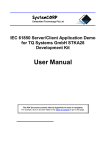
Software/Hardware CFE Internal Structure for Remote Terminal Units (RTU),
System Control Systems with Bay Control Units (BCU), and Distribution
Automation Systems (DAS):
Communication Front End structure
Flash Card
configuration
on power-up
Database
held in RAM
on CFE
PLC
Applications
CAN
Handler
Input/Output
Modules
Communication
Protocols
e.g. IEC 61850
Client
Server
Inteligent
Electronic Devices
DA System
SCS
Control
Master Station
Figure 4-1 – Overview of the WebCAN Communication Front End Structure
WebCAN Designer Studio
User and Reference Manual
Page 14 of 112
WEBCAN Substation
Control and
Monitoring System
WebCAN Designer Studio
User and Reference Manual
General Description
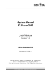
LAN
CFE 1
CFE 2
CFE 3
CFE 4
Up to 4 CFE-20 modules can be used in one RTU rack. See Hardware Description and User Manual for details.
Figure 4-2 – Overview or the Remote Terminal Unit (RTU) Structure
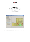
Bay
Control
Unit
Data Gateway
CFE Rack
Bay
Control
Unit
IEC 61850 LAN
Bay
Control
Unit
Bay
Control
Unit
Bay
Control
Unit
Bay
Control
Unit
Figure 4-3 – Overview of the Substation Control Structure with Bay Control Units (BCU)
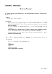
Substation
RTU
DA
Mini-RTU
DA
Mini-RTU
IEC 61850 Network
DA
Mini-RTU
e.g. VLAN, GPRS
DA
Mini-RTU
DA
Mini-RTU
DA
Mini-RTU
Figure 4-4 – Overview of the Distribution Automation System (DAS):
WebCAN Designer Studio
User and Reference Manual
Page 15 of 112
WEBCAN Substation
Control and
Monitoring System
WebCAN Designer Studio
User and Reference Manual
General Description
4.1 CFE File Configuration
4.1.1
Location of the CFE Files
All of the initialization, configuration, and user applications are stored into two partitions, A: and B: partitions. The
real-time operating system CFE settings are stored in A drive. The user applications and configuration created in
WebCAN Designer Studio are stored in B drive, which is the Secure Digital (SD) flash disk card.
Autoexec.bat, chip.ini
User Applications and PLC applications
User Configuration files
Flash Card
configuration
on power-up
Real-time Log files
File Name
AUTOEXEC.BAT
CHIP.INI
EXTSD.EXE
ETH1.EXE
Functions
Batch file for all startup programs
Settings file for the CFE (e.g. CFE name, IP address)
SD card driver (required to access B drive)
Required for Ethernet Port 2
Table 4-1 – CFE A: Drive Contents and their Functions
File Name
APPS.BAT
CANHDLR.EXE
DBSYSTEM.EXE
DIAGNOST.EXE
PLCDBHDL.EXE
PLCSYSTEM.EXE
PROTOCOL Executables
Functions
Batch file that controls the startup of the applications
CANOpen handler
Database system
Diagnostic application
PLC to database interface
PLC System
Protocol executable files (e.g. 61850)
Table 4-2 – CFE B:\APPS Folder Drive Contents and their Functions
File Name
CurrentProject.WDS
ASC (directory)
BIN (directory)
CFG (directory)
DCF (directory)
POE (directory)
XML (directory)
Functions
The project file that is currently active in the CFE
Ascii configuration files (for other Applications or Protocols)
Binary configuration files (ORT)
CFG configuration files (System, CFE and some applications)
DCF configuration files (IO modules)
POE configuration files (PLC)
XML configuration files (61850 protocol)
Table 4-3 – CFE B:\CONFIG Folder Contents and their Functions
WebCAN Designer Studio
User and Reference Manual
Page 16 of 112
WEBCAN Substation
Control and
Monitoring System
WebCAN Designer Studio
User and Reference Manual
General Description
4.2 WDS Demonstration Version
There are 2 versions of the WebCAN Designer Studio: 1) the purchased released production version, and 2) the
free demonstration version.
4.2.1
Limitations of the Demonstration Version
This document describes the production version of WebCAN Designer Studio. The demonstration version has the
following limitations:
User Administration – The demonstration version has no password security.
Download – The demonstration version can not download projects into any RTU, BCU, or DA hardware.
Manage Tools – The demonstration version can not Manage or change added software tools.
Diagnostics – The demonstration version can not communicate, monitor, or run diagnostics on any RTU,
BCU, or DA hardware.
Does not contain OpenPCS IEC61131 software.
All the associated pull-down and pop-up menus associated with the above list are disabled.
4.2.2
Saved Demonstration Projects may be Upward Compatible
WebCAN Designer Studio is protected against disassembly and reverse engineering. Project files have a 64-digit
encryption key used and are fully compressed.
WebCAN Designer Studio demonstration versions can be used to create and save projects. For security
purposes, the demonstration version cannot download the project to the
RTU hardware. However, these project files are upward compatible to the
fully-functional version. The Administrator user can read the
demonstration-created project and save the
project for the fully-function version.
Once the Administrator has opened and saved the
project created from the demonstration version, it
fully compatible with the RTU hardware.
As a security measure, projects created by the fully-functional version are not downward compatible to the
demonstration version. Attempting to access a secured project with the demonstration version will show the
message:
For more information on using User Administration, see the user guide section below and the User Administration
reference section.
Note: Please check with SystemCORP Pty Ltd that the demonstration version is current and compatible with
current production software if you wish to use it for project creation. The WDS versions and internal
application structure is subject to change without prior notice and projects created with older demonstration
versions may NOT be compatible. Demonstration version created projects should not be construed as a
commitment by SystemCORP Pty Ltd to be fully compatible with current production versions.
SystemCORP Pty Ltd does not assume responsibility for any errors with an older demonstration version.
WebCAN Designer Studio
User and Reference Manual
Page 17 of 112
WEBCAN Substation
Control and
Monitoring System
WebCAN Designer Studio
User and Reference Manual
General Description
The following section will offer a quick tour of the WebCAN Designer Studio software application introducing
terms, naming conventions, and the general application development environment. Greater detail of the
development environment is contained in later user and reference sections.
4.3 WebCAN Designer Studio Quick Walk-thru 3-Page Tour
When developing an application to run on the WebCAN Substation Control and Monitoring system hardware
[reference 3], the “WebCAN Designer” Studio Windows-based application tool is used for configuration:
WebCAN Designer (.exe) application creates project (*.WDS) files. The project file contains all
the information and data require for building the application that is downloaded to the WebCAN
Substation Control and Monitoring system hardware.
WebCANDesigner.exe Windows-based application – Open (Launch) the executable
Enter appropriate
Username and
Next ...
Password into the
Secure Login screen.
Your System Administrator
assigns Usernames and
passwords.
TOOLBOX
Next ...
The WDS
development
environment
window
appears:
OBJECT LIBRARY WINDOWPANE
OBJECT SETTINGS WINDOWPANE
PROJECT
WINDOWPANE
OBJECT PARAMETERS WINDOWPANE
TOOLBAR Basic functions
OBJECT LIBRARY Modules in the RTU
PROJECT WINDOW Graphic design of the project tree
OBJECT SETTINGS WINDOW Specific module settings
OBJECT PARAMETERS WINDOW Parameters for module settings
WebCAN Designer Studio
User and Reference Manual
Create your project by
using objects from the
OBJECT LIBRARY,
assembling in PROJECT
WINDOW; adjust settings in
the OBJECT SETTINGS and
PARAMETERS WINDOW.
Page 18 of 112
WEBCAN Substation
Control and
Monitoring System
WebCAN Designer Studio
User and Reference Manual
General Description
The OBJECT LIBRARY contains numerous software objects that are equivalent to the hardware modules and
represent other applications. Select the appropriate tab to drag and drop in the PROJECT WINDOW. All the
essential tabs (System, IO modules, Applications, and PLC) containing the appropriate objects are show below.
Additional tabs and objects are also available depending upon the protocols that are installed (e.g. IEC61850,
DNP3, GPRS Gateway).
Typical
Steps:
OBJECT LIBRARY
These icons represent
the hardware modules
and other applications.
1
2
3
4
Click-drag & drop
objects from the
OBJECT WINDOW to
the PROJECT WINDOW
Next ...
OBJECTS (icons of HW modules and applications):
CFE
RTU
NET
Communications Front End
Miniature Remote Terminal Unit
Network Group of the 4 CFEs on the rack
CanACT
Controller Area Network Application
Configuration Table for the IO Modules:
Analog DC Input Module
Digital Input Module
Analog AC (Alternating Current) Input Module
High Current Input Module
Low Current Input Module
AIM
DIM
ACM
HCM
LCM
PROJECT WINDOW
Assemble the project within this
windowpane.
WebCAN Designer Studio
User and Reference Manual
Diagnostic Stethoscope icon is the Diagnostic Application
EXT
External Applications
ACT
I/O
PLC and other Applications Configuration Table
PLC Input/Output reference variables
Page 19 of 112
WEBCAN Substation
Control and
Monitoring System
WebCAN Designer Studio
User and Reference Manual
Select Objects and
adjust appropriate
OBJECT SETTINGS
and PARAMETERS
WINDOW
Next ...
General Description
Each Object requires specific settings. For example, each CFE,
BCU, and DA RTU requires an IP Address.
For another example, each
I/O modules require specific
parameters such as …
Lastly ...
Select the TOOLBAR icon to save, compile and download, then diagnose the system:
Create a new WebCAN project.
Open a WebCAN project from disk.
Save the current WebCAN project.
Copy or ‘save as’ the current WebCAN project into different name (backup).
Print out the report for the completed WebCAN Designer project.
Compile (check design rules of) the current WebCAN project.
Start OpenPCS application from the current WebCAN project.
Compile and Download the current WebCAN project into the system.
Open the WebCAN project from actual CFE in the RTU, BCU, or DA RTU hardware.
Start system diagnostic for the current WebCAN project.
Congratulations! That’s all it takes to control and configure a SystemCORP substation monitoring and control
system.
For a more detailed walk-through example, in the next section see the Security & User Administration as well as
the Create a New System Design section.
WebCAN Designer Studio
User and Reference Manual
Page 20 of 112
WEBCAN Substation
Control and
Monitoring System
WebCAN Designer Studio
User and Reference Manual
WebCAN Designer
Studio User Guide
5 WebCAN Designer Studio User Guide
This section walks through the creation of a RTU project from beginning to end step-by-step:
5.1. Security & User Administration – How to create various users with different security settings.
5.2. Assembling and Editing a WebCAN Designer Studio Project – How to assemble each module.
5.3. Compile and Download to RTU, BCU, or DA RTU – How to load the project into the hardware.
5.4. Printing and Project Reports – Creating – How to generate configuration reports and print them.
5.5. WebCAN Designer Studio Tools – How to add and use other tools with WDS.
5.1 Security & User Administration
5.1.1
SystemCORP Administrator
When WebCAN Designer Studio is installed, the only user is the “SystemCorp” user. The SystemCorp user has
full administration rights. The SystemCorp user has the ability to create other users. Login as SystemCorp user:
The WebCAN Designer
Studio default system
Administrator User name
is “SystemCorp” and the
default password is
“SystemCorp”. User
names and passwords
are case sensitive and
allow numerical as well
as special characters.
SystemCorp
Figure 5-1 – Login screen for WebCAN Designer Studio
For example, John Smith may be the person assigned to be the administrator for use WebCAN Designer Studio.
John’s first task would be to assign himself a unique password. Next, he would add, edit, and remove users.
1) Select the User > User Administration menu item:
2) The User Administration dialog box will appear.
Select SystemCorp User.
3) To change user passwords, click on the Edit button.
4) On the User settings dialog box enter or change the
Username and/or
password.
5) Confirm password.
6) Click on OK button.
WebCAN Designer Studio
User and Reference Manual
Click here
to add a user
Click here to
remove a user
7) Add other users as required (e.g. tech, eng, diag).
Page 21 of 112
WEBCAN Substation
Control and
Monitoring System
WebCAN Designer Studio
User and Reference Manual
WebCAN Designer
Studio User Guide
To continue with this example, John Smith may continue with above procedure to create new users by using the
Add button, entering new users (e.g. create “JSmith” user as an “Engineer”). In the User settings dialog box enter
the Username, Password, and User Group. Note that both username and password are case sensitive.
There are 4 User types of users (or Groups) with default settings:
5.1.2
Administrator – has full access and cannot be changed.
Engineer – Similar to Administrator but cannot add or edit
users.
Technician – Can only edit, save, print, and run diagnostics.
Diagnostician – Can only open, print, and run diagnostics.
User Access
Click here to switch
between “Group
access rights” and
“Users” tab.
Group
Access
Rights
Click here to re-load
all default settings.
Figure 5-2 – User Administration default “Group Access Rights” settings
By default, only the Administrator type of user can change passwords, add, remove, edit the users, or the group
access rights table (i.e. “UserAdmin” “Group access rights” tick-box is ticked ). The Administrator user group
cannot be changed (i.e. “Group access rights” tick-boxes cannot be un-ticked for the Administrator user group).
This prevents an Administrator from locking themselves out of WebCAN Designer Studio.
See the pull-down menu User Administration reference section for a complete description for each “Group Access
Rights” tick item.
WebCAN Designer Studio
User and Reference Manual
Page 22 of 112
WEBCAN Substation
Control and
Monitoring System
WebCAN Designer Studio
User and Reference Manual
WebCAN Designer
Studio User Guide
5.2 Assembling and Editing a WebCAN Designer Studio Project
Logged into WebCAN Designer Studio as a user with full access rights for to creating, building, and saving a
project, the following screen (less the red lines and text for description in the document) will be presented:
1. Standard Windows title banner and Pull-down Menus
2. TOOLBOX
3. OBJECT LIBRARY WINDOWPANE
5. OBJECT SETTINGS WINDOWPANE
4. PROJECT
WINDOWPANE
6. OBJECT PARAMETERS WINDOWPANE
Figure 5-3 – WebCAN Designer Studio Windowpane Descriptions
Throughout this document, all the screens and menus show what is seen by a user with full access (i.e. an
Administrator). Other users may have menu items inaccessible. For example, the default Diagnostician user
Toolbox windowpane and pull-down menu items will have several items inaccessible (gray selections).
The 6 major parts of the WebCAN Designer Studio screen show:
1. Standard Windows title banner and Pull-down Menus.
2. Toolbox – the 10 most used icons: New, Open, Save, Save As (backup), Print, Check (compile), Check
and Download, Upload from the CFE, OpenPCS [refer 2], and System Diagnostics.
3. Object Library – Icons of objects that represents hardware modules [refer 3], other applications, and
optional protocols. The specific WebCAN Designer Studio installation may contain optional protocols. For
example, client and server protocol menus such as DNP3, GPRS Gateway, and/or IEC 61850 may or
may not be available.
4. Project Window – Construction of the design is done in this windowpane. Assemble the project design in
this windowpane by dragging and dropping objects from the Object Library windowpane into this
windowpane in the specific order as required. Error checking prevents assembly of objects in an incorrect
manner.
5. Object Settings – The settings for each object in the Project Windowpane are set in this windowpane.
6. Object Parameters – The parameters for each specific setting in the Object Settings windowpane are set
in this windowpane.
WebCAN Designer Studio
User and Reference Manual
Page 23 of 112
WEBCAN Substation
Control and
Monitoring System
5.2.1
WebCAN Designer Studio
User and Reference Manual
WebCAN Designer
Studio User Guide
Creating a New System Design with WebCAN Designer Studio
Also see “WebCAN Designer Studio Quick Walk-thru 3-Page Tour” above to see a quick complete design flow
overview.
As an example, the following 10 pages create this design specification from the beginning through to download
and diagnostics:
EXAMPLE Specification for “Station XYZ”
Use 2 Communication Front Ends (CFE). One contains the
Controller Area Network (CAN) with input/output modules, and
the other CFE Containing a SCADA Programmable Logic
Controller (PLC) application.
CFE1 “CAN_CFE”
o
Analog Alternating Current Input Module
o
Analog Direct Current Input Module
o
Digital Input Module
o
High Current Module
o
Low Current Module
CFE2 “Ctrl_PLC” SCADA application
Communication Front Ends (CFE's) both are networked together
and have the ability to directly drive The Output modules
(diagnostic application).
Redundant Master/Standby Time Sync Fibre Optic interface are
also used.
Once appropriately logged-in (an “Administrator” or “Engineer” default user), create the design specification in
WebCAN Designer Studio. Follow step-by-step to create the above example design specification for “Station
XYZ” described.
Save the project from time-to-time during the design entry process.
1) Edit the Object names in the
Project Windowpane. Click on
“SYSTEM_01” and change the
name to “STATION XYZ”.
2) Insert the design’s name,
description, ID, location, and time
zone in the Object
Windowpane.
3) Select the appropriate
mapping of the Time Sync
modules to the CFEs. Use pulldown menu to select “T1 and T2
module to CFE1” for this
example.
See System Object specific
description, settings and
parameter limits section. In
addition, the Object Library Windowpane tabs only show “System”, “IO Modules”, “Applications” and “PLC”. The
specific WebCAN Designer Studio installation may contain several other client and server protocol menus (e.g.
DNP3, GPRS Gateway, IEC 61850).
WebCAN Designer Studio
User and Reference Manual
Page 24 of 112
WEBCAN Substation
Control and
Monitoring System
WebCAN Designer Studio
User and Reference Manual
WebCAN Designer
Studio User Guide
4) Point to the CFE Object then click dragand-drop from Object Library here …
5) … to here in the Project
Windowpane on top of “STATION XYZ”.
6) Repeat again to place a second CFE.
CNTL_PLC
7) After placing both the CFE’s …
8) … click here change Object
Settings for CFE_01 then for
CFE_02 to rename. This is the
name that appears on the network.
For this example,
Name CFE_01 to “CAN_CFE”
Name CFE_02 to “CNTL_PLC”
9) Click to expand the CFE
Parameters for both CFE’s then …
10) … enter the
appropriate IP
address, masks,
and gateways.
To change the IP
Address, change
the “IP Address”
field.
This is the current address
of the RTU, BCU or DA
RTU CFE.
See the CFE Object specific description, settings and parameter limits section.
WebCAN Designer Studio
User and Reference Manual
Page 25 of 112
WEBCAN Substation
Control and
Monitoring System
WebCAN Designer Studio
User and Reference Manual
WebCAN Designer
Studio User Guide
11) Point to the NET Object then click dragand-drop from the Object Library here …
12) … to here on top of the CFE_01.
CNTL_PLC
13) Repeat again to
place a second NET
Object into CFE_02.
14) Select NET Object
NETWORK_GRP_01 tab.
15) Double-click in “Name” cell
so the “Reference lookup”
dialog box will appear.
When
complete, each
CFE will contain
a NET Object.
16) Select the CFE to network.
Network reference:
Refer CFE_01 to CFE_02
Note: Referenced names should always be taken
from the “Reference lookup” dialog box and not be
typed in manually or pasted into cell.
17) Click Update button to
connect the network
references.
See the NET Object specific description
settings and parameter limits section for
more information.
In this example,
CFE_01, NETWORK_GROUP_01 is linked
to CFE_02 that is named “CNTL_PLC”; while
CFE_02, NETWORK_GROUP_02 is linked
to CFE_01 that is named “CAN_CFE”.
WebCAN Designer Studio
User and Reference Manual
18) Click Close button.
19) Repeat again for NETWORK_GRP_02 reference
for CFE_02 by selecting NETWORK_GRP_02 tab
repeating steps 14 through 18 again.
Network reference: Refer CFE_02 to CFE_01
Page 26 of 112
WEBCAN Substation
Control and
Monitoring System
WebCAN Designer Studio
User and Reference Manual
WebCAN Designer
Studio User Guide
20) Select the IO Modules tab.
21) Point to the CANACT Object
then click drag-and-drop from here …
22) … to here on top of CFE_01 in the
Project Windowpane.
23) Repeat procedure again, for example,
select the Input module “ACM” in Object
Library windowpane then drag-and-drop
the “ACM” object on top of the
“CAN_ORT_01” object in the Project
Windowpane.
24) Repeat drag-and-drop again for each IO
module “AIM”, “DIM”, “HCM”, and “LCM”.
Each I/O Object has specific settings and parameters (e.g. individual channel
specifications, specific individual channel Object Names, Descriptions, time
parameters).
See the specific module Object Settings and Parameters sections for more
information;
WebCAN Designer Studio
User and Reference Manual
ACM – Analog AC Input Module
AIM – Analog DC Input Module
DIM – Digital Input Module
HCM – High Current Module
LCM – Low Current Module
Page 27 of 112
WEBCAN Substation
Control and
Monitoring System
WebCAN Designer Studio
User and Reference Manual
WebCAN Designer
Studio User Guide
In this example, a PLC program will drive the Low Current Module (LCM) outputs channels 1 through 5.
Therefore, the appropriate external variable names need to be referenced. The default names that appear may be
used or they can be renamed. The following describes how to change names or a group of names.
25) Select the LCM
module.
26) Tick the boxes Uncontrolled
Channels 1 through 5 on LCM.
27) Click and drag-select from the
Channel 1 Object Name cell to the
Channel 4 Object Name cell.
28) After selecting the channel
cells, use the right-mouse click on
top of the selected cells and select
the pop-up menu item “Column”
“Auto labelling”
29) Using the Auto label dialog box, enter a sequence
of names. In this example, create “RELAY_CH1”
through to “RELAY_CH4”.
To use Auto Label:
a. Enter the Object name “RELAY_CH” and the
number as “[C]”
(Note: uppercase “[C]”)
b. Numbering can be incremented or
decremented starting on any integer.
c.
Click Rename button after confirming the
“Preview value” is correct.
This will close the Auto label dialog box and channels 1 through 4 will be renamed to “RELAY_CH1”
through to “RELAY_CH4”.
30) By selecting a single cell, any specific cell name may change by simply typing in the cell. In this example,
select the cell for Object Name, Channel Number 5 then type “CNT_SIGNAL”.
A similar process of Settings and Parameters must be done for all other objects. For this particular example, look
at the other particular settings and parameters (e.g. ACM, AIM, DIM, HCM, LCM).
WebCAN Designer Studio
User and Reference Manual
Page 28 of 112
WEBCAN Substation
Control and
Monitoring System
WebCAN Designer Studio
User and Reference Manual
WebCAN Designer
Studio User Guide
31) Select the PLC tab.
32) Point to the ACT Object then click
drag-and-drop from here …
33) … to here on top of CFE_02 in
the Project Windowpane.
34) Double-click here and the
“Reference lookup” dialog will appear.
35) Define the PLC External
Variables by referring to the individual
channel Object Names that define
each specific Object in the Object
Settings Windowpane.
As with other objects the PLC Object requires settings and
parameters (e.g. a license key).
36) Click
on the LCM to expand to view the list of names.
37) First, select “RELAY_CH1” then click “Update” button.
38) Select each variable in turn and click on “Add new
reference” button repeatedly for each of the selected
remaining variables (“RELAY_CH2”, “RELAY_CH3”,
“RELAY_CH4”, then “CNT_SIGNAL”).
39) When complete, click on “Close”
button. The Object Settings
windowpane now show references.
WebCAN Designer Studio
User and Reference Manual
Page 29 of 112
WEBCAN Substation
Control and
Monitoring System
WebCAN Designer Studio
User and Reference Manual
WebCAN Designer
Studio User Guide
For this example, add the Diagnostic Application. By adding this application to the RTU hardware, WebCAN
Design Studio will be able to run a view all CAN activity in real-time. In addition, be able to probe and drive input
and output channels.
40) Select the Applications tab.
41) Point to the Diagnostic Object then
click drag-and-drop from here …
42) … to here on top of CFE_01 in
the Project Windowpane.
43) Repeat the drag-and-drop procedure again
with another Diagnostic Object on top of CFE_02.
When complete, both CFE’s will contain a DIAGACT.
See the Diagnostic Object specific description, settings and parameter limits section.
WebCAN Designer Studio
User and Reference Manual
Page 30 of 112
WEBCAN Substation
Control and
Monitoring System
WebCAN Designer Studio
User and Reference Manual
WebCAN Designer
Studio User Guide
44) Click the Save icon to save the WebCAN project.
45) Click the Error Check (compile) icon for the project.
Compiling will check the entire design for
errors. If the check is successful then a dialog
box with design
information and Save
button will appear.
Alert Messages will
appear in lower right
corner of the WDS window displaying the
errors. For this example, if a valid PLC
license does not exist then this Alert
Message will appear.
View all project Alert Messages any time by selecting the
“Alert Messages” under the View menu. (Also, see Alert Messages list.)
46) Click the Download icon button. Download Project windowpane appears.
Click “Save” as
required.
Confirm that the
CFE’s are available
on-line – Status:
“Connected via
LAN or USB”.
47) Click the
“Download
configuration to
selected CFE(s)”
button.
48) Once the download is 100% complete, the CFE(s) will reboot automatically
after a 5 second count down when the CFE(s) are 100% downloaded. Note that
closing this dialog tab prior to the reboot message will cancel rebooting CFE(s).
Note: Unless the hardware [reference 3] is configured as described in this
example the connection and download will not succeed.
49) Use Infoteam OpenPCS application to create the PLC program, click the OpenPCS icon to open the
OpenPCS application [references 1 and 2]. WebCAN Designer Studio has integrated OpenPCS by automatically
creating the OpenPCS environment
with the appropriate external
variables. In this example, all the PLC
references:
Note that Infoteam OpenPCS
requires a software licence key.
All Object references are passed
directly to the to the OpenPCS environment prior to the
download of the CFE(s). See information in Download section.
OpenPCS
WebCAN Designer Studio
User and Reference Manual
Page 31 of 112
WEBCAN Substation
Control and
Monitoring System
WebCAN Designer Studio
User and Reference Manual
WebCAN Designer
Studio User Guide
The downloaded design is now running.
50) Confirm that the CFE’s are now on line. In this example CFE_01 is named
“CAN_CFE” and CFE_02 is named “CNTL_PLC”. By selecting the Tools menu item
“CFE Information” a dialog box will appear showing the CFE names, network IP
address, and other information. Review that the system is online.
51) Start or stop searching for
CFE’s on network.
52) Close when completed review.
Run Diagnostics to view real-time activity occurring on the system.
53) Click the Diagnostic icon to enter WebCAN Designer Studio Diagnostic mode.
54) Right-mouse-click
on the design name and
select “Start diagnostic”.
For more details for using Diagnostics see the Diagnostic Section in this manual for more information.
WebCAN Designer Studio
User and Reference Manual
Page 32 of 112
WEBCAN Substation
Control and
Monitoring System
WebCAN Designer Studio
User and Reference Manual
WebCAN Designer
Studio User Guide
The above example walks through the design creation process from beginning to end. Numerous details for
setting Object Settings and Parameters have been omitted to convey the overall creation process. The
following pages describe the specific settings and parameters for each object. In addition, unless the hardware
[reference 3] is assembled as described in this example the connection, download, and diagnostics will not work
as described. The Diagnostic user guide and Diagnostic pop-up menu reference sections further describes the
use and features of diagnostics. The creation of a PLC program using OpenPCS is beyond the scope of this
document (for more information, refer to the OpenPCS manual [reference 2]).
To summarize creating a new design:
1. Click, drag-and-drop objects from the Object Library to Project Windowpane. CFE objects must be
placed first before placing other objects.
2. Edit the Object names, descriptions, and other settings in the Object Settings and Parameters
windowpane for each object placed in the Project windowpane. Enter Object Names one by one. Edit
other sequential lists one by one or by selecting the cells to edit then right-mouse-click the menu item to
column Auto label. Auto label allows the quick creation of names or descriptions that have a numerical
sequence. For example: CH3, CH2, CH1; CH2, CH4, CH6; CH13_3, CH14_2, CH15_1. CH16_0.
3. Save the WebCAN design project.
4. Error Check (compile) the project. Compiling will check the entire design for errors. “Alert Messages” will
appear in lower left corner of the WDS window displaying the errors.
5. Download the project.
a. Confirm that the CFE’s are available on-line (Status: “Connection established”).
b. Click the “Download configuration to selected CFE(s)” button.
6. Using Infoteam OpenPCS application create the PLC program as required. For details, see the OpenPCS
application references [1 and 2]. WebCAN Designer Studio integrated OpenPCS by automatically
creating the OpenPCS environment with the appropriate external variables. All Object References from
WebCAN Designer Studio are passed directly to the OpenPCS environment.
7. Enter diagnostics to view or directly drive the I/O module channels.
The following pages refer to the specific Object, Object Settings, and Object Parameters descriptions and limits
for every Object.
WebCAN Designer Studio
User and Reference Manual
Page 33 of 112
WEBCAN Substation
Control and
Monitoring System
WebCAN Designer Studio
User and Reference Manual
WebCAN Designer
Studio User Guide
5.2.1.1 SYSTEM Settings
The System object is the root, parent level or base for your design project. This object cannot be
removed.
SYSTEM_01 Settings:
Name
Description
ID
Location
Time Zone Hour
Time Zone Minutes
CAN modules
fibre-optic mapping
Default
WebCAN
WebCAN
description
1
WebCAN
location
8
00
Menu
Choices
2
0
Min
32
64
Max
Units
Text Characters
Text Characters
0
0
255
64
Numbers
Text Characters
-12
00
14
45
Hours
Minutes Drop Down
Drop-down menu
choices
NOTE: All text characters must be uppercase, underscores "_", and numbers only. No Spaces, ".", "-", or
special characters of any kind are allowed.
CAN modules fibre-optic mapping DropDown Menu choices:
T1 module to CFE 1. T2 module to CFE 3
T1 module to CFE 1. T2 module to CFE 4
T1 module to CFE 2. T2 module to CFE 3
T1 module to CFE 2. T2 module to CFE 4
T1 and T2 module to CFE 1
T1 and T2 module to CFE 3
Default value
Table 5-1 – System Settings
For T2 and T2 Hardware mapping see “Setting up the CANopen Fibre Network” section in hardware
manual [reference 3].
5.2.1.2 SYSTEM Parameters (none)
This OBJECT has no Parameters.
WebCAN Designer Studio
User and Reference Manual
Page 34 of 112
WEBCAN Substation
Control and
Monitoring System
5.2.2
WebCAN Designer Studio
User and Reference Manual
WebCAN Designer
Studio User Guide
Communications Front-End (CFE) Object
5.2.2.1 CFE Description
User Administration “EditProject” must be set.
Drag CFE from OBJECT Library
to SYSTEM in the PROJECT
Windowpane.
OR, use right-mouse
click pop-up menu over
SYSTEM in the Project
Windowpane and select
from “Add Object”.
Figure 5-4 – Add CFE object from Object Library to Project Windowpane
5.2.2.2 CFE Settings
CFE_01 Settings
Name
Description
Command Timeout
Command Arbitration
Timeout
Time Sync Arbitration
Timeout
LED
(This shows DB active)
Default
CFE No.1
CFE
[1,2,3 or 4]
Description
1000
10000
1
0
Min
32
64
Max
Units
Text Characters
Text Characters
1000
0
600000
600000
milliseconds
milliseconds
10000
0
600000
milliseconds
LED A
A
D
CFE LED on front
panel of hardware
Table 5-2 – CFE Settings
NOTE: All text characters must be uppercase, underscores "_", and numbers only. No Spaces, ".", "-", or
special characters of any kind are allowed.
WebCAN Designer Studio
User and Reference Manual
Page 35 of 112
WEBCAN Substation
Control and
Monitoring System
WebCAN Designer Studio
User and Reference Manual
WebCAN Designer
Studio User Guide
5.2.2.3 CFE Parameters
CFE Object Parameters:
CFE No
Ethernet Port 1
IP Address
NetMask
Default Gateway
Current IP Address
Ethernet Port 2
Ext IP Address
Ext NetMask
Ext Default Getway
Default
CFE NO 1
Min
1
Max
32
Description
CFE Number 1 thru 32
192.168.100.1
255.255.255.0
192.168.100.1
192.168.100.1
n/a
n/a
n/a
n/a
n/a
n/a
n/a
n/a
Unique CFE IP Address
192.168.100.2
255.255.255.0
192.168.100.1
n/a
n/a
n/a
n/a
n/a
n/a
External IP Address
CFE IP Address in rack
Table 5-3 – CFE Parameters
WebCAN Designer Studio
User and Reference Manual
Page 36 of 112
WEBCAN Substation
Control and
Monitoring System
5.2.3
WebCAN Designer Studio
User and Reference Manual
WebCAN Designer
Studio User Guide
Network (NET) Object
5.2.3.1 NET Description
User Administration “EditProject” must be set.
This object is required to interconnect multiple CFE’s.
Drag NET from OBJECT Library
to a CFE in the PROJECT
Windowpane.
OR, use right-mouse
click pop-up menu over
a CFE in the Project
Windowpane and select
from “Add Object”.
Figure 5-5 – Add NET object from Object Library to Project Windowpane
5.2.3.2 NET Settings
NET Settings:
Name
Description
Description
Reference lookup from other CFEs
Reference lookup from other CFEs text
Table 5-4 – NET Settings
5.2.3.3 NET Parameters (none)
This OBJECT has no Parameters.
WebCAN Designer Studio
User and Reference Manual
Page 37 of 112
WEBCAN Substation
Control and
Monitoring System
5.2.4
WebCAN Designer Studio
User and Reference Manual
WebCAN Designer
Studio User Guide
Mini Remote Terminal Unit (RTU) Object
5.2.4.1 RTU Description
User Administration “EditProject” must be set.
This stripped-down single CFE can be networked into the RTU rack
and/or other mini RTUs.
Drag RTU from OBJECT
Library to SYSTEM in the
PROJECT Windowpane.
OR, use right-mouse
click pop-up menu over
SYSTEM in the Project
Windowpane and select
from “Add Object”.
Figure 5-6 – Add CFE object from Object Library to Project Windowpane
5.2.4.2 RTU Settings
RTU Settings:
Name
Description
Consumer Port
Status Port
Command Timeout
Command Arbitration
Timeout
Time Sync Arbitration
Timeout
CFE Startup Time
LED
Default
MiniRTU No.1
CFE
Description
10000
10000
10000
10000
0
0
Min
255
255
Max
Units
Text Characters
Text Characters
0
0
1000
0
65000
65000
60000
60000
Integer
Integer
Milliseconds
Milliseconds
10000
0
60000
Milliseconds
12000
LED A
0
A
60000
D
Milliseconds
CFE LED
Table 5-5 – RTU Settings
NOTE: All text characters must be uppercase, underscores "_", and numbers only. No Spaces, ".", "-", or
special characters of any kind are allowed.
5.2.4.3 RTU Parameters
RTU Object Parameters:
RTU No
Internal Network Settings
IP Address
NetMask
Default Gateway
Command Port
Current IP Address
External Network Settings
Ext IP Address
Ext NetMask
Ext Default Getway
Default
1
192.168.100.1
255.255.255.0
192.168.100.1
11000
192.168.100.1
Min
1
4
Max
0
65000
Description
CFE Number 1, 2, 3, or 4
192.168.100.1
255.255.255.0
192.168.100.1
Table 5-6 – RTU Parameters
WebCAN Designer Studio
User and Reference Manual
Page 38 of 112
WEBCAN Substation
Control and
Monitoring System
5.2.5
WebCAN Designer Studio
User and Reference Manual
WebCAN Designer
Studio User Guide
CAN Application Configuration Table (CANACT) Object
5.2.5.1 CANACT Description
User Administration “EditProject” must be set.
This is the parent or base to attach
the Input and Output module objects.
Drag CANACT from OBJECT Library to
a CFE in the PROJECT Windowpane.
OR, use right-mouse
click pop-up menu over
a CFE in the Project
Windowpane and select
from “Add Object”.
Figure 5-7 – Add CANACT object from Object Library to Project Windowpane
5.2.5.2 CANACT Settings
CANACT Settings:
Name
Default
CAN_HANDLER_1
1
Min
32
Max
Description
CAN Handler Appl
0
64
App Number
1
1
20
Units
Text
Characters
Text
Characters
Integer –
Automatically
assigned
Table 5-7 – CANACT Settings
NOTE: All text characters must be uppercase, underscores "_", and numbers only. No Spaces, ".", "-", or
special characters of any kind are allowed.
5.2.5.3 CANACT Parameters
CANACT Object Parameters:
Application Enabled
WebCAN Designer Studio
User and Reference Manual
Default
True
Min
Max
Description
False True
Tick Box or
Table 5-8 – CANACT Parameters
Page 39 of 112
WEBCAN Substation
Control and
Monitoring System
5.2.6
WebCAN Designer Studio
User and Reference Manual
WebCAN Designer
Studio User Guide
Analog Input Module (ACM) Alternating Current (AC) Object
5.2.6.1 ACM Description
User Administration “EditProject” must be set.
Drag ACM from OBJECT Library to
a CAN_ORT in the PROJECT
Windowpane.
OR, use right-mouse
click pop-up menu over
a CAN_ORT in Project
Windowpane and select
from “Add Object”.
Figure 5-8 – Add ACM object from Object Library to Project Windowpane
Object Settings Windowpane
WebCAN Designer Studio
User and Reference Manual
Page 40 of 112
WEBCAN Substation
Control and
Monitoring System
WebCAN Designer Studio
User and Reference Manual
WebCAN Designer
Studio User Guide
5.2.6.2 ACM Settings
ACM Settings:
ACM
Object Name
Object Description
Delta (%)
Lower Limit
Voltage:
Nominal Value
Frequency:
Nominal Value
Current:
Nominal Value
Active Power:
Nominal Value
Reactive Power:
Nominal Value
Apparent Power:
Nominal Value
Power Factor:
Nominal Value
Spare:
Nominal Value
Default
No Tick
Min
No Tick
Max
Tick
1
0
0
0
0
65535
65535
65535
0
65535
0
65535
0
65535
0
65535
0
65535
0
65535
0
65535
110000
Units
Tick Box or
Text Characters
Text Characters
Percentage
Integer
Volts
50
Hz
5000
Amps
550000
Watts
550000
Watts
550000
Watts
550000
Watts
550000
Watts
Table 5-9 – ACM Settings
NOTE: All text characters must be uppercase, underscores "_", and numbers only. No Spaces, ".", "-", or
special characters of any kind are allowed.
5.2.6.3 ACM Parameters
ACM Object Parameters:
Node ID
CPU ID
Read Cycle Time (ms)
Active Busbar
Node Description
Default
1
1
500
1
1 Node
1 Description
Min
1
Max
15
1
0
1
0
2
65535
2
64
Description
Identification of I/O Module
set in hardware. See
“Node ID Configuration
using the DSP-10” section
[Reference 3].
Identification of CPU.
Menu choice 50 or 60 Hz
Text Characters
Table 5-10 – ACM Parameters
WebCAN Designer Studio
User and Reference Manual
Page 41 of 112
WEBCAN Substation
Control and
Monitoring System
5.2.7
WebCAN Designer Studio
User and Reference Manual
WebCAN Designer
Studio User Guide
Analog Input Module (AIM) Direct Current (DC) Object
5.2.7.1 AIM Description
User Administration “EditProject” must be set.
Drag AIM from OBJECT Library to
a CAN_ORT in the PROJECT
Windowpane.
OR, use right-mouse
click pop-up menu over
a CAN_ORT in Project
Windowpane and select
from “Add Object”.
Figure 5-9 – Add AIM object from Object Library to Project Windowpane
5.2.7.2 AIM Common Settings
AIM Common Settings:
AI
AI TAP
Object Name
Object Description
Max Current (in mA)
Averaging
Default
No Tick
No Tick
AIM_1_N3
Obj Descript
21
1
Min
No Tick
No Tick
1
0
20
1
Max
Tick
Tick
32
64
21
900
Units
Tick Box or
Tick Box or
Text Characters
Text Characters
Milliamps
Integer
Table 5-11 – AIM Common Settings
NOTE: All text characters must be uppercase, underscores "_", and numbers only. No Spaces, ".", "-", or
special characters of any kind are allowed.
5.2.7.3 AIM Common Parameters
AIM Common Parameters:
Node ID
CPU ID
Frequency (in Hertz)
Node Description
Default
1
1
50
1 Node
1 Description
Min
1
Max
15
1
50
0
2
60
64
Description
Identification of I/O Module
set in hardware. See
“Node ID Configuration
using the DSP-10” section
[Reference 3].
Select integer
Menu choice 50 or 60 Hz
Text Characters
Table 5-12 – AIM Common Parameters
WebCAN Designer Studio
User and Reference Manual
Page 42 of 112
WEBCAN Substation
Control and
Monitoring System
WebCAN Designer Studio
User and Reference Manual
WebCAN Designer
Studio User Guide
5.2.7.4 AIM AI and AI TAP Channel Settings and Parameters
5.2.7.4.1
AI Specific Settings
AI Channel Settings:
Min Overflow
Low Low Alarm
Low Alarm
High Alarm
High High Alarm
Max Overflow
Delta %
Default
-20
-19
-18
18
19
20
5
Min
-25
-25
-25
-25
-25
20
0
Max
25
25
25
25
25
20
65535
Units
Integer
Integer
Integer
Integer
Integer
Integer
Percentage
Table 5-13 – AI Channel Specific Settings
AI Specific Object Parameters: None
5.2.7.4.2
AI TAP Specific Settings
AI TAP Channel Settings:
Start Position
Start Current (mA)
End Position
End Current (mA)
Validation Time (ms)
Validation Dead Band %
Default
1
0
31
19
0
0
Min
1
-21
2
-21
0
0
Max
30
20
31
20
65000
100
Units
Integer
Milliamps
Integer
Milliamps
Milliseconds
Percentage
Table 5-14 – AI TAP Channel Specific Settings
AI TAP Specific Object Parameters: None
WebCAN Designer Studio
User and Reference Manual
Page 43 of 112
WEBCAN Substation
Control and
Monitoring System
5.2.8
WebCAN Designer Studio
User and Reference Manual
WebCAN Designer
Studio User Guide
Digital Input Module (DIM) Object
5.2.8.1 DIM Description
User Administration “EditProject” must be set.
Drag DIM from OBJECT Library
to a CAN_ORT in the PROJECT
Windowpane.
OR, use right-mouse
click pop-up menu over
a CAN_ORT in Project
Windowpane and select
from “Add Object”.
Figure 5-10 – Add DIM object from Object Library to Project Windowpane
WebCAN Designer Studio
User and Reference Manual
Page 44 of 112
WEBCAN Substation
Control and
Monitoring System
WebCAN Designer Studio
User and Reference Manual
WebCAN Designer
Studio User Guide
5.2.8.2 DIM Common Settings
DIM Channel Setting:
SPI
Default
No Tick
Min
No Tick
Max
Tick
DPI
No Tick
No Tick
Tick
TAP
No Tick
No Tick
Tick
BCD
Counter
No Tick
No Tick
1 BCD = 4-5
No Tick
7 BCD = 28-29
Tick
Object Name
Object Description
Inverted
ON Filter Time
OFF Filter Time
DIM_#_N#_CH#
Digital input Node# Channel#
27
0
64
Inverts signal state for negative logic.
No Tick
No Tick
Tick
The validation times that the input must be in the ON state
before the transition is accepted as valid.
0
0
60000
The validation times that the input must be in the OFF
state before the transition is accepted as valid.
0
0
60000
Units
Tick Box
or
Tick Box
or
Tick Box
or
Tick/Dialog
Tick Box
or
Text
Text
Tick Box
or
Milliseconds
Milliseconds
Table 5-15 – DIM Common Settings
5.2.8.3 DIM Common Parameters
DIM Object Parameters:
Node ID
Node Description
Default
1
1 Node
1 Description
Min
1
Max
15
0
64
Description
Identification of I/O Module
set in hardware. See
“Node ID Configuration
using the DSP-10” section
[Reference 3].
Text Characters
Table 5-16 – DIM Common Parameters
WebCAN Designer Studio
User and Reference Manual
Page 45 of 112
WEBCAN Substation
Control and
Monitoring System
WebCAN Designer Studio
User and Reference Manual
WebCAN Designer
Studio User Guide
5.2.8.4 Digital Input Module SPI, DPI, TAP, BCD, and Counter Input Channels
User Administration “PasteProject” must be set.
The field termination Digital Input Module (DIM) is fully integrated in the unit. It has disconnect switches
and test points for all input channels. A total of 64 input channels can be configured as:
Single (SPI below) or Double Point Inputs (DPI) with adjustable ON/OFF filter time, inverse logic
and automatic suppression options
Transformer TAP Position Inputs with a maximum of 64 TAP positions
BCD Inputs configurable from 1 to 7 digits and strobe/timer trigger option
Rising edge (Type A) or Rising & falling edge (Type B) Counters with configuration option for
cyclic or polled reporting
5.2.8.4.1
DIM SPI (Single Digital Input) Specific Settings
Selecting SPI causes this column to appears
Tick the appropriate 1 to 64 SPI channels
SPI Specific Setting:
Auto Suppression
Tick Inverted for negative logic
and ON/OFF Filter Time to accept
transition as valid.
See “DIM Common Settings” for
above for more in information.
Description
Default
Minimum
Maximum
When ticked , Auto Suppression stops false readings (of
jitter) less than configurable Parameter Suppression Time
and Release Time.
No Tick
No Tick
Tick
Units
Tick Box
or
Table 5-17 – DIM SPI Specific Settings
WebCAN Designer Studio
User and Reference Manual
Page 46 of 112
WEBCAN Substation
Control and
Monitoring System
WebCAN Designer Studio
User and Reference Manual
WebCAN Designer
Studio User Guide
SPI Specific Object Parameters:
SPI Object
Parameters:
Node ID
Transitions
Suppression Time
Release Time
Node Description
Description
Default
Minimum
Maximum
Identification of I/O Module set in hardware. See “Node ID
Configuration using the DSP-10” section [Reference 3].
Units
1
1
15
The first 0-1-transition of a signal starts the control
according to Automatic Suppression. The channel starts
counting the transitions and the end of suppression
window is calculated. If the counter reaches the number
of configured transitions and the end of suppression
windows is not reached, the channel will be suppressed.
integer
1
1
255
If Auto Suppression Setting Ticked then this is, the
amount of time required to acknowledge a valid signal.
integer
1000
0
18000
If Auto Suppression Setting Ticked then this is, the
amount of time required after a signal to read the next
valid signal.
The release window starts if no further transition is
detected. Each new transition will restart the release
window again.
1000
1 Node
1 Description
0
0
18000
64
Milliseconds
by 1000’s
Milliseconds
By 1000’s
Text
Characters
Table 5-18 – DIM SPI Specific Parameters
WebCAN Designer Studio
User and Reference Manual
Page 47 of 112
WEBCAN Substation
Control and
Monitoring System
5.2.8.4.2
WebCAN Designer Studio
User and Reference Manual
WebCAN Designer
Studio User Guide
DIM DPI (Double Digital Input) Specific Settings
The valid and normal initial start-up condition of Double Digital Inputs is 01 or 10.
If the initial start-up condition is 00 then a change of state must occur within the allotted “Invalid Time”
Setting. It is then recorded as Valid. If the initial start-up condition of 00 does no change state within the
allotted “Invalid Time” Setting then it is recorded as Invalid.
If the start-up condition is 11 the input is reported as “invalid” immediately.
00
01
10
11
Valid data only if changes within allotted “Invalid Time” Object Setting
Valid DDI data
Valid DDI data
Reported as Invalid data immediately
Selecting DPI causes these columns to appears
Tick the appropriate 1 to 32 DPI channels
DPI Specific Setting:
Valid Time
Invalid Time
Tick Inverted for negative logic
and ON/OFF Filter Time to accept
transition as valid.
See “DIM Common Settings” for
above for more in information.
Description
Default
Minimum
Maximum
Minimum amount of time allotted for DDI to be in the Valid
“01” or “10” states
0
0
1000
Maximum amount of time allotted for DDI to be in the “00”
illegal state.
0
0
1000
Units
Milliseconds
Milliseconds
Table 5-19 – DIM DPI Specific Settings
DPI Specific Object Parameters:
Node Description
WebCAN Designer Studio
User and Reference Manual
1 Node
1 Description
0
64
Text
Characters
Page 48 of 112
WEBCAN Substation
Control and
Monitoring System
5.2.8.4.3
WebCAN Designer Studio
User and Reference Manual
WebCAN Designer
Studio User Guide
DIM TAP (transformer binary tap position) Specific Settings
Tick Inverted for negative logic
and ON/OFF Filter Time to accept
transition as valid.
See “DIM Common Settings” for
above for more in information.
Tick the appropriate TAP channels and a TAP dialog box will appear:
Next, choose the appropriate Number of 1 to 64
TAP channels.
Only one input channel can be active at a time for
a valid tap position. If more than one input is
active then there must be a fault with the
equipment and the tap position reading is
reported as Invalid.
TAP Specific Setting:
Default
Description
Minimum
Units
Maximum
Number of Channels
1
1
64
integer
Table 5-20 – DIM TAP Specific Settings
TAP Specific Object Parameters:
TAP Object
Parameters:
TAP Offset
Change Time
Node Description
Description
Default
Min
Max
An offset value for a double-wound transformer.
0
-63
0
Amount of time required before next signal.
0
0
60000
1 Node
0
64
1 Description
Units
integer
Milliseconds
Text
Characters
Table 5-21 – DIM TAP Specific Parameters
WebCAN Designer Studio
User and Reference Manual
Page 49 of 112
WEBCAN Substation
Control and
Monitoring System
5.2.8.4.4
WebCAN Designer Studio
User and Reference Manual
WebCAN Designer
Studio User Guide
DIM BCD (Binary Coded Decimal) Specific Settings
Selecting BCD causes these columns to appears
Tick Inverted for negative logic
and ON/OFF Filter Time to accept
transition as valid.
See “DIM Common Settings” for
above for more in information.
Tick the BCD channels starting at channel 1 or ending on channel 64. In other words, a BCD input must
start on channel 1 or end on the 64th channel (Note: An error will occur during compile/download if an the
BCD does not start at channel 1 or end on
channel 64).
When a BCD is ticked a dialog box will appear.
Choose 1 to a total of 7 digits.
Next, choose Strobe or Timer.
BCD Specific Setting:
Number of digits
Strobe
Timer
Validation Time
Default
1
Description
Minimum
1
Units
Maximum
7
Integer
Strobe radio button in dialog box causes a tick mark on
column to display which channel is the Strobe.
1000
1000
60000
1000
1000
1000
Button and
Tick display
Milliseconds
Milliseconds
Table 5-22 – DIM BCD Specific Settings
WebCAN Designer Studio
User and Reference Manual
Page 50 of 112
WEBCAN Substation
Control and
Monitoring System
WebCAN Designer Studio
User and Reference Manual
WebCAN Designer
Studio User Guide
The intended application of the BCD digital input module is to hardwire directly to the encoded
to Binary Coded Decimal (BCD) driving the 7 segments of a seven-segment display(s).
Hexadecimal
0
1
2
3
4
5
6
7
8
9
a
b
C
d
E
F
7-Segment Display Segments
a
1
0
1
1
0
1
1
1
1
1
1
0
1
0
1
1
b
1
1
1
1
1
0
0
1
1
1
1
0
0
1
0
0
c
1
1
0
1
1
1
1
1
1
1
1
1
0
1
0
0
d
1
0
1
1
0
1
1
0
1
1
1
1
1
1
1
0
e
1
0
1
0
0
0
1
0
1
0
1
1
1
1
1
1
f
1
0
0
0
1
1
1
0
1
1
0
1
1
0
1
1
Encoded 7-Segment
Binary Bits
g
0
0
1
1
1
1
1
0
1
1
1
1
0
1
1
1
D
0
0
0
0
0
0
0
0
1
1
1
1
1
1
1
1
C
0
0
0
0
1
1
1
1
0
0
0
0
1
1
1
1
B
0
0
1
1
0
0
1
1
0
0
1
1
0
0
1
1
WebCAN
Data
WebCAN
Status
0
1
2
3
4
5
6
7
8
9
10
11
12
13
14
15
OK
OK
OK
OK
OK
OK
OK
OK
OK
OK
IV
IV
IV
IV
IV
IV
A
0
1
0
1
0
1
0
1
0
1
0
1
0
1
0
1
Table 5-23 – DIM BCD 7-Segment Display Truth Table
BCD Specific Object Parameters:
Node Description
WebCAN Designer Studio
User and Reference Manual
1 Node
1 Description
0
64
Text
Characters
Page 51 of 112
WEBCAN Substation
Control and
Monitoring System
5.2.8.4.5
WebCAN Designer Studio
User and Reference Manual
WebCAN Designer
Studio User Guide
DIM Counter (Accumulator) Specific Settings
Selecting Counter causes these columns to appears
Tick Inverted for negative logic
and ON/OFF Filter Time to accept
transition as valid.
See “DIM Common Settings” for
above for more in information.
Counter Specific
Setting:
Counter Mode
Periodic Time
Reset
Default
Description
Minimum
Accumulate risingedges only.
Mode A:
2 counts
Accumulate both the
rising and falling edges
Mode B:
2 counts
Units
Maximum
Mode A
Mode A
Mode B
Periodic Time specifies the amount of time to accumulate
the signal transitions before reporting the count. No
accumulation readings occur if Periodic Time = 0 ms.
0
0
65000
When ticked the accumulator reports its total, the
accumulator is reset to zero
No Tick
No Tick
Ticked
Menu select
2 Modes
Milliseconds
Tick Box
or
Table 5-24 – DIM Counter Specific Settings
Counter Specific Object Parameters:
Node Description
WebCAN Designer Studio
User and Reference Manual
1 Node
1 Description
0
64
Text
Characters
Page 52 of 112
WEBCAN Substation
Control and
Monitoring System
5.2.9
WebCAN Designer Studio
User and Reference Manual
WebCAN Designer
Studio User Guide
High Current Output Module (HCM) Object
5.2.9.1 HCM Description
The Digital Current Output Module (HCM) supports controlled outputs. The output channels are
subdivided in 8 channels for “Trip” and for “Close” outputs. Either “Trip” or “Close” output is activated at
any one time. The operation method for this controlled output is called “three stage commands”.
Regardless of whether “Trip” or “Close”, only one HCM output is activated at any one time with the
exception of “Load shedding”, an Object Parameter.
Software Security
For secure software operation a three-stage command (Select, Arm and Execute) is used for operating a
controlled output. Each step of the sequence must receive a positive response from the actual output
driver before the next step may begin. Only if all three stages are completed and the data contained in
each stage is consistent is the output actually activated. Any inconsistencies in the stages will result in the
control output sequence being aborted. At each step there is a pre-configured timeout initiated. If a
response is not received within the timeout period then the response is assumed to be negative and the
control output sequence aborted and cleared down. The flow chart below shows a three-stage-command.
CFE Application
Output Select
HCM
CAN
Verifies Receive Message
Select Ack
Verifies Response Message
Output Arm
Switches Master Relay
Verifies Receive Message
Arm Ack
Verifies Response Message
Output Execute
Verifies Receive Message
Execute Ack
Switches Output Relay
Hardware Security
The hardware for the controlled outputs supports the Select-Arm-Execute concept with read-back
verification. The master contact is closed at the “Arm” stage. After switching a master relay the weld
monitor becomes active. The contact weld monitor and the read-back verification are used to check that
the digital output card circuitry is operational. If the contact weld monitor is active then the HCM is
functional (i.e. no welding of a contact). The command CAN response an acknowledge (ACK) and the
next stage can be performed.
If the contact weld monitor is passive one of the contacts is welded and the opto-coupler of the monitor
does not switch (it is short linked by the welded contact). In this case, the master relay is de-energized
immediately and error message (NACK) occurs.
It is only at the “Execute” stage that power is actually applied to the contacts by activating the selected
output relays.
WebCAN Designer Studio
User and Reference Manual
Page 53 of 112
WEBCAN Substation
Control and
Monitoring System
WebCAN Designer Studio
User and Reference Manual
WebCAN Designer
Studio User Guide
User Administration “EditProject” must be set.
Drag HCM from OBJECT Library to
a CAN_ORT in the PROJECT
Windowpane.
OR, use right-mouse
click pop-up menu over
a CAN_ORT in Project
Windowpane and select
from “Add Object”.
Figure 5-11 – Add HCM object from Object Library to Project Windowpane
5.2.9.2 HCM Settings
HCM Channel Settings:
Controlled
Object Name
Object Description
Pulse Time
Select with Value
Default
No Tick
HCM_#_N#_CH#
Digital output
HC# Node#
Channel#
1000
Tick
Min
No Tick
1
Max
Tick
32
0
64
0
No Tick
60000
Tick
Units
Tick Box or
Text Characters
Text Characters
Tick Box or
Table 5-25 – HCM Settings
NOTE: All text characters must be uppercase, underscores "_", and numbers only. No Spaces, ".", "-", or
special characters of any kind are allowed.
5.2.9.3 HCM Parameters
HCM Object Parameters:
Node ID
1
Default
CPU ID
Command Timeout
Load Shedding
1
2000
True
Node Description
1 Node
1 Description
Min
1
Max
15
1
0
False
0
2
32000
True
64
Description
Identification of I/O Module
set in hardware. See
“Node ID Configuration
using the DSP-10” section
[Reference 3].
Identification of CPU.
Tick Box or
Text Characters
Table 5-26 – HCM Parameters
WebCAN Designer Studio
User and Reference Manual
Page 54 of 112
WEBCAN Substation
Control and
Monitoring System
5.2.10
WebCAN Designer Studio
User and Reference Manual
WebCAN Designer
Studio User Guide
Low Current Output Module (LCM) Object
5.2.10.1
LCM Description
The Low Current Output Module (LCM) supports 16 output channels. Each of the channels can be
configured as “Uncontrolled” or “Pulse Train” outputs. Controlled outputs are independently controlled
relays. Pulse Train outputs Object Settings can configure the pulse width on and off as well as the
number of pulses.
User Administration “EditProject” must be set.
Drag LCM from OBJECT Library to
a CAN_ORT in the PROJECT
Windowpane.
OR, use right-mouse
click pop-up menu over
a CAN_ORT in Project
Windowpane and select
from “Add Object”.
Figure 5-12 – Add LCM object from Object Library to Project Windowpane
5.2.10.2
LCM Settings
LCM Channel Settings:
UnControlled
Pulse Train (R/L)
Object Name
Object Description
If Pulse Train ticked :
Pulse Time (ON)
If Pulse Train ticked :
Pulse Time (OFF)
If Pulse Train ticked :
Pulse Count
Default
No Tick
No Tick
LCM_#_N#_CH#
Digital Output
LC# Node#
Channel#
1000
Min
No Tick
No Tick
1
Max
Tick
Tick
32
Units
Tick Box or
Tick Box or
Text Characters
Text Characters
0
64
0
60000
Milliseconds
0
0
60000
Milliseconds
1
0
255
Milliseconds
Table 5-27 – LCM Settings
NOTE: All text characters must be uppercase, underscores "_", and numbers only. No Spaces, ".", "-", or
special characters of any kind are allowed.
WebCAN Designer Studio
User and Reference Manual
Page 55 of 112
WEBCAN Substation
Control and
Monitoring System
5.2.10.3
WebCAN Designer Studio
User and Reference Manual
WebCAN Designer
Studio User Guide
LCM Parameters
LCM Object Parameters:
Node ID
CPU ID
Command Timeout
Node Description
Default
1
1
2000
1 Node
1 Description
Min
1
Max
15
1
0
0
2
32000
64
Description
Identification of I/O Module
set in hardware. See
“Node ID Configuration
using the DSP-10” section
[Reference 3].
Text Characters
Table 5-28 – LCM Parameters
WebCAN Designer Studio
User and Reference Manual
Page 56 of 112
WEBCAN Substation
Control and
Monitoring System
5.2.11
WebCAN Designer Studio
User and Reference Manual
WebCAN Designer
Studio User Guide
Diagnostic Object
5.2.11.1
Diagnostic Description
User Administration “EditProject” must be set.
The diagnostic object must be placed in the
CFE(s) to be able to run real-time System
Diaganotics.
Drag Diagnostic from OBJECT Library to
a CFE in the PROJECT Windowpane.
OR, use right-mouse
click pop-up menu over
a CFE in the Project
Windowpane and select
from “Add Object”.
Figure 5-13 – Add Diagnostic object from Object Library to Project Windowpane
5.2.11.2
Diagnostic Settings
Diagnostic Settings:
Name
Description
App Number
Default
Diagnostic
Min
Max
1
1
0
1
32
64
20
LED
LED B
A
D
Diagnostic Port
3100
0
65000
Units
Text Characters
Text Characters
Integer –
Automatically
assigned
Diagnostic LED
on CFE panel
Integer
Table 5-29 – Diagnostic Object Settings
NOTE: All text characters must be uppercase, underscores "_", and numbers only. No Spaces, ".", "-", or
special characters of any kind are allowed.
5.2.11.3
Diagnostic Parameters
Diagnostic Object Parameters:
Application Enabled
Default
True
Min
False
Max
True
Description
Tick Box or
Table 5-30 – Diagnostic Object Parameters
WebCAN Designer Studio
User and Reference Manual
Page 57 of 112
WEBCAN Substation
Control and
Monitoring System
5.2.12
WebCAN Designer Studio
User and Reference Manual
WebCAN Designer
Studio User Guide
External Application (EXT) Object
5.2.12.1
EXT Description
User Administration “EditProject” must be set.
This object is use for adding user-defined
applications
Drag EXT from OBJECT Library to
a CFE in the PROJECT
Windowpane.
OR, use right-mouse
click pop-up menu over
a CFE in the Project
Windowpane and select
from “Add Object”.
Figure 5-14 – Add EXT object from Object Library to Project Windowpane
5.2.12.2
EXT Settings
External App Settings:
Name
IP Address
App Number
Default
Ext App
Name
External
Consumer
Application
192.168.1.1
1
Clock Sync Priority
LED
0
None
Description
1
Min
32
Max
Units
Text Characters
0
64
Text Characters
1
20
0
None
50
A, B, C, D
Internet Address
Integer –
Automatically
assigned
Integer
Ext LED
Table 5-31 – EXT Settings
NOTE: All text characters must be uppercase, underscores "_", and numbers only. No Spaces, ".", "-", or
special characters of any kind are allowed.
5.2.12.3
EXT Parameters
EXT Object Parameters:
Application Enabled
Default
True
Min
False
Max
True
Description
Tick Box or
Table 5-32 – EXT Parameters
WebCAN Designer Studio
User and Reference Manual
Page 58 of 112
WEBCAN Substation
Control and
Monitoring System
5.2.13
WebCAN Designer Studio
User and Reference Manual
WebCAN Designer
Studio User Guide
PLC Application Configuration Table (ACT) Object
5.2.13.1
PLC ACT Description
User Administration “EditProject” must be set.
This object is required to run SCADA PLC
61131 applications (e.g. OpenPCS projects).
Drag ACT from OBJECT Library to
a CFE in the PROJECT
Windowpane.
OR, use right-mouse
click pop-up menu over
a CFE in the Project
Windowpane and select
from “Add Object”.
Figure 5-15 – Add ACT object for PLC from Object Library to Project Windowpane
5.2.13.2
PLC ACT Settings
PLC ACT Settings:
Name
Description
App Number
Default
PLC1131_1
PLC 1131
Description
1
OpenPCS Port
LicKey
Command Timeout
8888
1
10000
Min
Max
Units
Text Characters
Text Characters
1
0
32
64
1
20
0
1 character
0
65000
16 characters
60000
Integer –
Automatically
assigned
Integer
OpenPCS Licence #
Integer
Table 5-33 – PLCACT Settings
NOTE: All text characters must be uppercase, underscores "_", and numbers only. No Spaces, ".", "-", or
special characters of any kind are allowed.
5.2.13.3
PLC ACT Parameters
PLCACT Object Parameters:
Application Enabled
Default
True
Min
False
Max
True
Description
Tick Box or
Table 5-34 – PLCACT Parameters
WebCAN Designer Studio
User and Reference Manual
Page 59 of 112
WEBCAN Substation
Control and
Monitoring System
5.2.14
WebCAN Designer Studio
User and Reference Manual
WebCAN Designer
Studio User Guide
PLC Input/Output (I/O) Object
5.2.14.1
PLC IO Description
User Administration “EditProject” must be set.
This object is used to reference I/O in a PLC
application.
Drag I/O from OBJECT Library to
a PLC1131ORT in the PROJECT
Windowpane.
OR, use right-mouse
click pop-up menu over
a PLC1131ORT in the
Project Windowpane
and select from “Add
Object”.
Figure 5-16 – Add I/O object for PLC from Object Library to Project Windowpane
5.2.14.2
PLC IO Settings
PLC IO Settings:
Object Name
Object Description
Data Type:
Description
Reference lookup from other CFEs
Reference lookup from other CFEs text
Single Point
Double Point
Unsigned Byte
Signed Byte
Unsigned Word
Signed Word
Unsigned Double Word
Signed Double Word
Table 5-35 – PLC IO Settings
5.2.14.3
PLC IO Parameters (None)
This OBJECT has no Parameters.
WebCAN Designer Studio
User and Reference Manual
Page 60 of 112
WEBCAN Substation
Control and
Monitoring System
5.2.15
WebCAN Designer Studio
User and Reference Manual
WebCAN Designer
Studio User Guide
Protocol Client / Server Objects
5.2.15.1
Protocol Description
User Administration “EditProject” must be set.
From the numerous protocols
see the appropriate manuals.
For example, see the
IEC61850, DNP3, GPRS,
IEC870-5-101 manuals.
These menu tabs are shown
only if you have these
protocols
5.2.15.2
Protocol Settings
Protocol Settings:
Name
Description
App Number
Clock Sync Priority
LED
(Shows Protocol active)
Default
Min
Max
1
1
0
1
32
64
20
0
NONE
0
NONE
50
A, B, C, or
D
Units
Text Characters
Text Characters
Integer –
Automatically
assigned
Integer
CFE LED on
hardware panel
Table 5-36 – Protocol Settings
NOTE: All text characters must be uppercase, underscores "_", and numbers only. No Spaces, ".", "-", or
special characters of any kind are allowed.
5.2.15.3
Protocol Parameters
Each protocol OBJECT may have their appropriate Parameters.
WebCAN Designer Studio
User and Reference Manual
Page 61 of 112
WEBCAN Substation
Control and
Monitoring System
WebCAN Designer Studio
User and Reference Manual
WebCAN Designer
Studio User Guide
5.3 Compile and Download/Upload to/from the RTU, BCU, or DA RTU CFEs
5.3.1
Compile (Design Check)
User Administration “CompileProject” must be set.
Compile does an error check of the design rules. This check builds a
completed system of the entire project ready that can be saved for
download.
Running a check may be done during the construction of the project at any
time to check for errors.
During the compile, a running
percentage of completion shows the
progress of the design rule check.
After starting the compile, the “Saving”
dialog box appears to allowing the
opportunity to save the present and
previous checked design.
It will NOT save after 15 seconds if no
action is selected. A countdown of the 15 seconds will be displayed.
If there are any errors then they are shown in
the Alert Messages dialog box that appears
in the lower-right corner of the WebCAN
Designer Studio window. For example:
Once a design has been successfully compiled, a “Compilation is successful” dialog box will appear
displaying design information:
During the development process of
the project, there may be numerous
design iterations and compilations to
check for errors. Thus, these
intermediate versions may be saved
or discarded.
Figure 5-17 – Compile Dialog Box
It is always good practice to Save or
WebCAN Designer Studio
User and Reference Manual
Save As … the design occasionally.
Page 62 of 112
WEBCAN Substation
Control and
Monitoring System
5.3.2
WebCAN Designer Studio
User and Reference Manual
WebCAN Designer
Studio User Guide
Download
User Administration “DownloadProject” must be set.
If a design has not been compiled then the compilation is automatically
executed prior to Download. View “Alert Messages” for design errors, if
necessary.
Only after a
successful
compilation the
POE Configuration dialog box appears.
Click “Yes” to pass the WDS Object Names
to OpenPCS’s External Variables source code.
This “Project downloads” tab ONLY appears after all design errors have been check and corrected:
The connection to the CFE in the
RTU, BCU, or DA RTU must be
established prior to commencing a
download. The status is shown to be
“Connected” via LAN or USB, or may
show “Failed to connect”. Check
network cable “Retry connection”.
A successful compilation can be
achieved but a failure to connect is
possible if the IP address information
simply does match the CFE’s actual
address. Check the IP address
information is correct as described in
the CFE Parameters section.
Click “Download configuration to selected CFE(s)” button to download to the
selected CFE’s. The hardware will automatically reboot after the download is successful. By ticking the
“Close After Download” tick box will automatically close this windowpane tab when the CFE(s) starts to
reboot.
Figure 5-18 – Download project to the CFE Hardware dialog box
Progress is shown while WebCAN Designer
Studio is downloading via FTP to the CFE
hardware in parallel.
Once completed the progress bar
will show 100% and a countdown
to CFE(s) rebooting begins.
Canceling the reboot of the CFE(s) may
be done prior to seeing the reboot message:
If the download tab is closed prior to the
completion of the CFE reboot countdown, as
shown in the lower-left corner of the
windowpane, then the CFE(s) will NOT be
rebooted.
The complete the entire WebCAN Designer project is stored in the CFE’s flash memory.
WebCAN Designer Studio
User and Reference Manual
Page 63 of 112
WEBCAN Substation
Control and
Monitoring System
5.3.3
WebCAN Designer Studio
User and Reference Manual
WebCAN Designer
Studio User Guide
Upload
User Administration “UploadProject” must be set.
Where Download copies the entire project to the CFE(s), Upload copies the
entire project from the selected CFE.
When downloaded, the entire project
is stored. Thus, by uploading a
project the entire WebCAN Designer
Studio project loaded in CFE
hardware’s flash memory on the
RTU, BCU, or DA RTU is re-loaded
back into the WebCAN Designer
Studio.
Insert the appropriate CFE IP
address information and then click
“Open project” button.
Available CFE IP addresses can be
found using the CFE Information tool
that displays CFE’s and their IP
addresses on the network.
Figure 5-19 – Upload project from the CFE hardware dialog box
WebCAN Designer Studio
User and Reference Manual
Page 64 of 112
WEBCAN Substation
Control and
Monitoring System
WebCAN Designer Studio
User and Reference Manual
WebCAN Designer
Studio User Guide
5.4 Print Project Report and Printing
5.4.1
Print Report
User Administration “Printing” must be set.
Print Report:
A compile (design check) is run for printing a report. In other words, the
Print Report is a completed project design, free of errors. Printing individual
tables does not require the design to be compiled.
Compile must be
successful.
Information in report:
Cover Page
Project Summary
Communication
Parameters
Reference List
Device Settings
Diagnostic Log
Buttons & Tick Box
Figure 5-20 – Print Report Dialog box – Report Setup/Printing Tab
“Print current report” – Clicking this button will print the current report of only the selected pages.
“Reset to Default Settings” – Clicking this button will change all the Print Setup pages to the default.
“ Use Same Print Settings for All (Except Cover Page)” – Ticking the tick box will automatically pop
up the Print Setup dialog box to set all page Print Setup, except the Cover Page.
“Ok” – Click to exit this Report Setup/Printing dialog box.
The following pages define the tabs Project Summary, Communication Parameters, Reference list,
Device Settings, and Diagnostic log information that will be part of the report. Each section can be
reviewed view “Print Preview” and fonts, font style, header/footer information, etc. can be defined with
“Print Setup”.
Note that the preview shows only the report data information and a screen view print driver should be
used (e.g. a PDF file creator) to view actually printout.
WebCAN Designer Studio
User and Reference Manual
Page 65 of 112
WEBCAN Substation
Control and
Monitoring System
5.4.2
WebCAN Designer Studio
User and Reference Manual
WebCAN Designer
Studio User Guide
Project Summary
This is the information
that is printed on the
cover page.
All the Items (e.g. CFE 1,
CFE 2) are listed in the
Project Summary page of
the report summarizing all
the data types and total
point count.
Figure 5-21 – Print Report Dialog box –Project Summary Tab
5.4.3
Communication Parameters
This tab shows the
report page covering all
the communication details
such as all the CFE and
application IP addresses,
command, consumer, and
status ports.
Figure 5-22 – Print Report Dialog box – Communications Parameters Tab
WebCAN Designer Studio
User and Reference Manual
Page 66 of 112
WEBCAN Substation
Control and
Monitoring System
5.4.4
WebCAN Designer Studio
User and Reference Manual
WebCAN Designer
Studio User Guide
Reference List
This tab shows the
report page covering all
the Object reference
names and data types.
Figure 5-23 – Print Report Dialog box – Reference List Tab
5.4.5
Device Settings
This tab defines what specific tables with settings and parameters are to be part of the report. Be default
there are no devices selected (i.e. there are NO Device names listed on the right-hand side of this tab).
This tab defines and
shows the report page
covering selected Device
Settings.
To select devices:
1) Click on desired
device, then
2) Click “Add>” button
to add the device to the
print report list.
Figure 5-24 – Print Report Dialog box – Report Setup/Printing Tab
All devices may be added or removed and, “Select” items may also be removed.
Note: The selection of devices is ONLY available in the current WebCAN Designer Studio session and
the selection is not saved to the project.
WebCAN Designer Studio
User and Reference Manual
Page 67 of 112
WEBCAN Substation
Control and
Monitoring System
5.4.6
WebCAN Designer Studio
User and Reference Manual
WebCAN Designer
Studio User Guide
Diagnostic Log
This tab defines what information from a selected diagnostic log are to be part of the report. Furthermore,
the selected log file events can be filtered as required.
Only the Diagnostic
events shown here will
be part of the report.
To define what
Diagnostic log file and
specific events to be
part of the report:
1) Click “Open
Diagnostic File” and
select the log file for
the report.
Figure 5-25 – Print Report Dialog box – Diagnostic Tab
2) After selecting the diagnostic log file, this dialog box will
appear. Select the section of the log file to be part of report
and then click “Ok”.
Note that “Start of Diagnostic log” to the “End of “Diagnostic
log” may be the only choices unless user defined Markers
have been placed in the log file. Also see Diagnostic Section
for more information.
All the events from
the selected file and
selected sections
appear.
To further select
specific events:
3) Define a filter for
the report.
In the example above, the filter will only show events with an “IV NT” status or Object Name “LCM_CH1”.
WebCAN Designer Studio
User and Reference Manual
Page 68 of 112
WEBCAN Substation
Control and
Monitoring System
WebCAN Designer Studio
User and Reference Manual
WebCAN Designer
Studio User Guide
4) Click on the
“Apply Selected Filter”
button so all the
events from the
selected file will
appear.
In this example, “IV
NT” Status or Object
Name “LCM_CH1”
events are the only
events shown.
Figure 5-26 – Print Report Dialog box – Diagnostic Log Tab with Filters
Other filters may be added and only the Enabled filters will be applied. Further description of log
filtering can be found in the Diagnostic Log Filters section.
WebCAN Designer Studio
User and Reference Manual
Page 69 of 112
WEBCAN Substation
Control and
Monitoring System
5.4.7
WebCAN Designer Studio
User and Reference Manual
WebCAN Designer
Studio User Guide
Print Setup
Figure 5-27 – Print Setup
5.4.7.1 Print Setup General
Borders:
+ Changes the lines surrounding the cells.
General:
+ General section changes
how the printed page fits on
the specified paper size.
+ To print the graphics (e.g. “”) on tables, tick “ Print graphics”.
Fonts:
+ Fonts section specifies what fonts, styles, and size are to be printed.
+ By ticking “Use display font” overrides the specified fonts and uses
the displayed default fonts.
WebCAN Designer Studio
User and Reference Manual
Page 70 of 112
WEBCAN Substation
Control and
Monitoring System
WebCAN Designer Studio
User and Reference Manual
WebCAN Designer
Studio User Guide
5.4.7.2 Print Setup Headers/Footers
Date / Time:
Format (e.g. dd/mm/yyyy)
+ Date / Time section
places the position of the
date and time on the page.
Title:
+ Title section changes the
title and the position.
Page Numbers:
+ Page Numbers section
changes the page format
and the position.
WebCAN Designer Studio
User and Reference Manual
Page 71 of 112
WEBCAN Substation
Control and
Monitoring System
WebCAN Designer Studio
User and Reference Manual
WebCAN Designer
Studio User Guide
5.4.7.3 Print Setup Margins
Margins:
+ This section changes the space around the printed page.
Spacing:
+ This section changes the space around each cell on the printed page.
Orientation:
+ This Orientation section changes the
printed page direction to the length or the
width.
WebCAN Designer Studio
User and Reference Manual
Page 72 of 112
WEBCAN Substation
Control and
Monitoring System
WebCAN Designer Studio
User and Reference Manual
WebCAN Designer
Studio User Guide
5.4.7.4 Print Setup Preferences
Save settings:
+ All the settings in the General, Headers / Footers, and Margins settings
can “Save settings” and then “Load settings” for other printing sessions.
WebCAN Designer Studio
User and Reference Manual
Page 73 of 112
WEBCAN Substation
Control and
Monitoring System
5.4.8
WebCAN Designer Studio
User and Reference Manual
WebCAN Designer
Studio User Guide
Print Preview
By selecting Print Preview the selected settings in the General, Headers / Footers, and Margins sections
will be displayed:
WebCAN Designer Studio
User and Reference Manual
Page 74 of 112
WEBCAN Substation
Control and
Monitoring System
WebCAN Designer Studio
User and Reference Manual
WebCAN Designer
Studio User Guide
5.5 WebCAN Designer Studio Tools
Tools for WebCAN Designer Studio are added, deleted, and
configured from the “ManageTools”, Tools pull-down menu.
Depending upon the WDS configuration, the Tools menu may or
may not have OpenPCS and/or ICD Designer.
5.5.1
Manage Tools
User Administration “ToolsConfig” must be set.
Other tools and applications may be opened from within WebCAN Designer Studio’s Tools pull-down
menu. Add the appropriate
Menu name text to appear on menu.
By selecting Browse button allows
selection of other applications that will
appear at the bottom of the Tools pulldown menu.
Click Save to complete action adding
item to tools menu.
Select and delete to remove items
from the tool menu.
Close Tools Configuration dialog box
when done.
This menu item will appear to only the user groups ticked. The Administrator always has access.
For example, the Notepad application can be added to WDS for an “Engineer” user:
Type in what would appear on menu.
Selecting “Browse” to select the item
to execute.
Click “Save” to save new menu item.
WebCAN Designer Studio
User and Reference Manual
Page 75 of 112
WEBCAN Substation
Control and
Monitoring System
5.5.2
WebCAN Designer Studio
User and Reference Manual
WebCAN Designer
Studio User Guide
CFE Information
This tool menu item cannot be deleted from Tools menu. The CFE Information displays the real-time
online CFE network information:
These CFE’s may be anywhere on the RTU, BCU, or DA RTU network
5.5.3
Ping
Ping is a basic Internet tool that allows a user to verify that a particular IP address exists and can accept
requests. Ping is a diagnostic tool to check that WebCAN Designer Studio can see that the CFE(s) is
actually operating. Ping works by sending
an Internet Control Message Protocol
(ICMP) Echo Request to a specified
interface on the network and waiting for a
reply. Ping tests connectivity and
determines response time.
This tool menu item cannot be deleted
from Tools menu.
5.5.4
Diagnostic
See the following System Diagnostic section. This too menu item cannot be deleted from Tools menu.
5.5.5
OpenPCS
Opens the external OpenPCS application.
For more information, see the OpenPCS manual [reference 1,2]
For troubleshooting, see External Application troubleshooting section.
WebCAN Designer Studio
User and Reference Manual
Page 76 of 112
WEBCAN Substation
Control and
Monitoring System
WebCAN Designer Studio
User and Reference Manual
System Diagnostic
User Guide
6 System Diagnostic User Guide
User Administration “Diagnostic” must be set.
System Diagnostic icon or Tools / Diagnostic pull-down menu item enter
System Diagnostics.
System Diagnostics is a real-time interface from the WebCAN Designer
Studio design and the actual system hardware.
To view either Diagnostics or the
project switch between the tabs.
Right-mouse click on SYSTEM or
individual CFE or MiniRTU.
Select “Start diagnostic”. Log starts …
1. Objects Lists
Windowpane
… here in the Global
Diagnostic Log windowpane.
2. Diagnostic Log
Windowpane
3. Project Tree
Windowpane
Figure 6-1 – System Diagnostic Environment Window
The System Diagnostic operating mode contains 3 windowpanes:
1. Objects Lists Windowpane – Each tab is an object list of channels showing real-time data once
diagnostics have been started.
2. Diagnostic Log Windowpane – Real-time display of events are displayed. Events can be filtered so
specific events can be found (e.g. Filter events by Channel or CFE number, object tag name, or data).
3. Project Tree Windowpane – Identical to Project Windowpane are displayed but on right side of window
and un-editable.
These windowpanes can be managed using right mouse-click pop-up menu (e.g. the windowpanes can placed in
their own independent windows and monitoring CFE Serial Ports).
WebCAN Designer Studio
User and Reference Manual
Page 77 of 112
WEBCAN Substation
Control and
Monitoring System
WebCAN Designer Studio
User and Reference Manual
System Diagnostic
User Guide
6.1 Diagnostic Log
6.1.1
Global Diagnostic Log
6.1.1.1 Save Logfile
All events are automatically saved in the file:
$HOME\Application Data\SystemCorp\Designer\Diagnostics\{WDSprojectname}~yyyymmdd_hh-mm-ss.log For example:
C:\Documents and Settings\John\Application Data\SystemCorp\Designer\Diagnostics\System XYZ~20090609_14_20_57.log
At any time, a current ‘snap-shot’ of the log can be saved by clicking the “Save Logfile” button.
Stops and
starts the
automatic
scrolling of the
current events.
User defined Markers
(a text line that can be
searched placed in
current position of the
log file) can be added
to the log file.
Jumps to last
event that
has occurred
on top row.
Figure 6-2 – Global Diagnostic Log Windowpane
All activities or every event appears in the Global Diagnostic Log. New events appear on the top row.
Each event is assigned a unique “Event count” number.
The channel number, Object Name, CFE number, data, date stamp, time stamp, status, object class, and
object number is shown for every event.
Further features described in the Diagnostic Pop-up Menus reference section.
WebCAN Designer Studio
User and Reference Manual
Page 78 of 112
WEBCAN Substation
Control and
Monitoring System
WebCAN Designer Studio
User and Reference Manual
System Diagnostic
User Guide
6.1.1.2 Columns in Global Diagnostic Log
Global Diagnostic
Log columns
Channel No.
Object Name
CFE No.
Data
Date Stamp
Time Stamp
Status
Object Class
Object No.
Event count
Description
Every object has a channel number. Every channel number on I/O
modules refer to the actual hardware channel number.
All data points in the system database are objects and all physical
hardware modules (e.g. CFE’s, I/O modules) are objects. The object
name is unique to the project. These are all modelled in software and
appear as objects in diagnostics.
Communication Front End number where object is located is shown.
Actual data that appears on that specific channel is displayed.
Date stamp shown in Day / Month / Year format.
Time shown in 24 hour clock format to the millisecond.
Status of the data displayed (see Log Status Description table below).
Specific type number of object.
Object numbers are unique within each CFE. Note CFE No. in addition to
the Object No.
Unique number assigned to the current activity or event that has occurred.
Table 6-1 – Columns in Global Diagnostic Log
Status
OK
BL
CA
CY
IV
NT
OV
SB
Description
Valid data – Data is correct.
A value is correct if the Object value was correctly acquired.
Blocked – The value of the Object is blocked for transmission.
The value remains in the state that was acquired before it was blocked. For example,
blocking and de-blocking may be initiated by a local lock or a local automatic cause.
Counter was adjusted – Counter was adjusted since last reading.
Carry – Counter overflow occurred in the corresponding integration period.
Invalid data – Data is incorrect.
A value is valid if it was correctly acquired. After the acquisition function recognizes
abnormal conditions of the information source (missing or non-operation updating
devices) the value is then marked invalid. The value of the Object is not defined
under this condition. The marked invalid is used to indicate to the destination that the
value may be incorrect and cannot be used.
Not Topical – Not updated properly.
A value is topical if the most recent update was successful. If not topical then Object
was not updated successfully during a specified time (setting or parameter) interval or
it is unavailable.
Over Flow – Data is beyond limit.
The value of the Object is beyond a predefined range of value mainly applicable to
analog values.
Substitution – Value has been substituted.
The value of the Object is provided by input of an operator (in WebCAN Designer
Studio by diagnostic Substitution), or by an automated source.
Table 6-2 – Global Diagnostic Log Status Descriptions
WebCAN Designer Studio
User and Reference Manual
Page 79 of 112
WEBCAN Substation
Control and
Monitoring System
WebCAN Designer Studio
User and Reference Manual
System Diagnostic
User Guide
6.1.1.3 Log Filters
Events can be filtered to display only specific events.
Select these tabs to view all the
events or view only the events defined
by a logical filter.
Every event will appear in the Global Diagnostic Log including normal maintenance events such as GPS
time synchronization or starting of other applications. If there are specific objects and channels to be
monitored then specific events can be reported in the “Filtered Log”.
The “Log Filter” can be defined by channel, name, CFE, data, date, time, status, object class or object
numbers. For example, Log Filter can show only channel 39 or those events with an “IV” (invalid) status.
Figure 6-3 – Defining Diagnostic Log Filter Example
Filters may contain wildcard characters. As in the above example on the second row ‘CH*_LCM*’ uses
the ‘*’ wildcard to define an object name beginning with ‘CH’ and containing the characters ‘_LCM’. The ‘*’
denotes any number of characters after the ‘CH’ or after the ‘_LCM’.
All the filter descriptions on any enabled row must be true for the event to be reported on the filtered log.
For example, if the second row above was also enabled then all object names beginning with ‘CH’ and
containing the characters ‘_LCM’ and only in CFE number ‘2’ will be reported. This enabled row or the
first or third enabled row will then report ‘CH*_LCM*’ only in CFE 2 or channel 39 or any invalid statusl.
Both arithmetic arguments and logical operators may also be used.
Summary of filter definitions:
Wildcards:
[Characters]* Where “*” denotes multiple character matches
[Characters]? Where “?” denotes single character matches
Arithmetic:
>
is greater-than
<
is less-than
>= is greater-than or equal-to
<= is less-than or equal-to
=
is equal-to
!
is not equal-to
Logical must be used with “(” and “)”:
& is a logical AND
^
is a logical OR, or
;
is a logical OR
For example a filter definition of (=4)^(>=9)&(<=15)&(!13) would report only the events where the event is
a 4, 9, 10, 11, 12, 14, or 15. Note that the “(“ and “)” must be used with the logical operators.
WebCAN Designer Studio
User and Reference Manual
Page 80 of 112
WEBCAN Substation
Control and
Monitoring System
WebCAN Designer Studio
User and Reference Manual
System Diagnostic
User Guide
Any 1 to 5 filters can be “Enabled” . The “Start Selected Filters” tick box is ticked to start the “Filtered
log” to display only those filters created.
Only
these
events
are
shown.
The “Global Diagnostic Log” shows all events. The “Filtered log” in this example only
shows only channel number 39 and those with an “IV” (invalid) status.
WebCAN Designer Studio
User and Reference Manual
Page 81 of 112
WEBCAN Substation
Control and
Monitoring System
WebCAN Designer Studio
User and Reference Manual
System Diagnostic
User Guide
6.2 Diagnostic Monitoring
6.2.1
Substitute
Right-mouse click
on channel to select
Substitute. The dialog
box “Substitute”
appears:
For example, substitute a data “2”.
Click on “Substitute” button to execute.
The application of “Substitution” is used for
testing the system before the station is
commissioned and wired to the I/O modules.
Data substituted
and status is “SB”.
Substituting digital outputs does not operate the selected output channel. Substitution is only displayed on
the DSP-10 display and marked accordingly in the system database.
WebCAN Designer Studio
User and Reference Manual
Page 82 of 112
WEBCAN Substation
Control and
Monitoring System
6.2.2
WebCAN Designer Studio
User and Reference Manual
System Diagnostic
User Guide
Direct Drive
Right-mouse click
on channel to directly
drive an output value
(in this example,
channel 2 on
LCM1620_01).
“Drive output” forces a direct change to a module’s channel.
As an added security measure, the user forcing the drive must
login again by confirming their password.
After a successful login, the Drive Output
dialog box allows the setting of data
directly to the selected channel.
Click the “Drive output” button to execute.
WebCAN Designer Studio
User and Reference Manual
Page 83 of 112
WEBCAN Substation
Control and
Monitoring System
6.2.3
WebCAN Designer Studio
User and Reference Manual
System Diagnostic
User Guide
Counter Operation
This diagnostic tool allows the viewing of the DIM (counter) accumulator.
Right-mouse click
on channel to select
Counter Operation –
dialog box appears:
Click on “Counter operation” to read the
accumulator (counter).
Note that the counter values may be reported by event timer as defined by the DIM
Counter “Periodic Time” settings. The counter data may optionally be reset after
reporting the periodic event. See DIM Counter inputs section under the Digital Input
Module description for more information.
Freeze without reset when “Periodic Time = 0 ms”
The counter reports its total value, but continues to accumulate the value without
resetting the value.
Freeze with reset when “Periodic Time = 0 ms”
When the counter reports its total, the accumulator is reset to zero and the counter next
period begins.
WebCAN Designer Studio
User and Reference Manual
Page 84 of 112
WEBCAN Substation
Control and
Monitoring System
WebCAN Designer Studio
User and Reference Manual
Reference
7 Reference
7.1 Toolbar Windowpane
For all the menu selections to appear, the appropriate User Administration
settings must be set “”. See User Administration Group Access Rights
section for more information.
Figure 7-1 – Toolbar Windowpane
Create a new WebCAN project. User Administration “EditProject” must be set.
Open and re-open a WebCAN project from disk. User Administration “OpenProject” must
be set.
Save the current WebCAN project. User Administration “SaveProject” must be set.
Copy or ‘save as’ the current WebCAN project into different name (backup).
User Administration “SaveProject” must be set.
Print out the report for the completed WebCAN project. This is the completed design;
therefore, the report is error free. See Print Section for more details.
User Administration “Printing” must be set.
Compile the current WebCAN project. See Compile (check) and Download Project
section for more details. User Administration “CompileProject” must be set.
Start OpenPCS application from the current WebCAN project.
Requires a Infoteam OpenPCS license key.
Compile and Download the current WebCAN project into the system. See Compile and
Download section for more details. Set “DownloadProject” in User Administration.
Open the WebCAN Designer Studio project from a CFE.
User Administration “UploadProject” must be set.
Start system diagnostic for the current WebCAN project.
User Administration “Diagnostic” must be set.
WebCAN Designer Studio
User and Reference Manual
Page 85 of 112
WEBCAN Substation
Control and
Monitoring System
WebCAN Designer Studio
User and Reference Manual
Reference
7.2 Menu Bar Menus
This section describes all the pull-down menus.
For all the menu selections to appear, the appropriate User
Administration settings must be set “”. See User Administration
Group Access Rights section for more information.
7.2.1
File Pull-down Menu
7.2.1.1 Import New Database
This menu item imports EDS data files. Only available to
Administrators and any user with User Administration access
group with UpdateEDS ticked.
7.2.1.2 Export Database to EDS files
This menu item exports EDS data files. Only available to
Administrators and any user with User Administration access
group with UpdateEDS ticked.
7.2.1.3 Exit
Exit will exit the WebCAN Designer Studio application.
7.2.2
Edit Pull-down Menu
7.2.2.1 Copy
Copies selection to clipboard.
7.2.2.2 Copy Selected Reference Node(s)
Copies selected nodes from table to clipboard.
7.2.2.3 Paste
Pastes contents of clipboard to current position.
7.2.2.4 Paste Selected Referece Node(s)
Pastes node contents of clipboard to current position.
User Administration “PasteTable” must be set.
7.2.2.5 Fill Down
Fills table column with the first selected cell contents.
WebCAN Designer Studio
User and Reference Manual
Page 86 of 112
WEBCAN Substation
Control and
Monitoring System
7.2.3
WebCAN Designer Studio
User and Reference Manual
Reference
View Pull-down Menu
7.2.3.1 Alert & Info Messages
This menu item will display the current Alert and Info Messages for
the current project in the lower right-hand corner of the screen. For
details of the 2 types of messages see the Messages and Dialog
boxes section.
If there are no Alert or Info messages a
no messages dialog box will appear:
A complete list of Alert Messages is under Trouble Shooting section – see
the Alert Messages in that section.
7.2.4
Project Pull-down Menu
7.2.4.1 Create New Project
Same as in Toolbox windowpane.
7.2.4.2 Open Project
Same as in Toolbox windowpane.
7.2.4.3 Save Project
Same as in Toolbox windowpane.
7.2.4.4 Copy Project
Same as in Toolbox windowpane.
7.2.4.5 Compile Project
Same as in Toolbox windowpane.
7.2.4.6 Download Project
Same as in Toolbox windowpane.
7.2.4.7 Print Project Report
Same as in
n Toolbox windowpane. See Print Section.
Section
7.2.4.8 Reopen Project
Displays a list of recent projects to open. User Administration “OpenProject” must be set.
WebCAN Designer Studio
User and Reference Manual
Page 87 of 112
WEBCAN Substation
Control and
Monitoring System
WebCAN Designer Studio
User and Reference Manual
Reference
7.2.4.9 About Current Project
Shows WDS version that created this project.
Shows complete path to this project.
Show the current project file name.
Show last time and date the file was saved.
Show username and access group of creator.
Show the last time project was checked.
Show the number of times file saved.
Show any description that has been entered.
Figure 7-2 – About Current Project
7.2.5
Tools Pull-down Menu
Pull-down Menu items described in WebCAN Designer
Tool section.
Depending upon the WDS configuration, the Tools menu
may or may not have OpenPCS and/or ICD Designer.
For all the menu selections to appear, the appropriate User Administration settings “ToolsConfig” must be
set “”. See User Administration Group Access Rights section for more information.
WebCAN Designer Studio
User and Reference Manual
Page 88 of 112
WEBCAN Substation
Control and
Monitoring System
7.2.6
WebCAN Designer Studio
User and Reference Manual
Reference
User Pull-down Menu
7.2.6.1 User Administration
An Administrator has access or User Administration “UserAdmin” must be set.
Click “Add” button to add additional users. Select a user
then click “Edit” button to change username, password, or
user group access; or click “Remove” button to delete user.
Username and Password are case sensitive.
Click here to
close dialog box
Click here to
remove a user
There are 4 User types of users (or Groups) with the default settings:
Administrator – has full access and cannot be changed.
Engineer – Similar to Administrator but cannot add or edit users.
Technician – Can only edit, save, print, and run diagnostics.
Diagnostician – Can only open, print, and run diagnostics.
The access definitions for the Engineer, Technician, and Diagnostician may be altered by the Administrator or by
any user with the group access item UserAdmin ticked.
Administrator Access Rights are all ticked and unable to be un-tick. The Administrator has access to all
features and cannot be changed.
Engineer Access Rights are all ticked except UserAdmin. The Engineer default is identical to an Administrator
except they cannot add, edit, or change users or these group access rights.
Technician Access Rights are all ticked except NetworkSetup, UserAdmin,ToolsConfig, or UpdateEDS. The
Technician default does not have the ability to create new projects but has the ability to edit existing projects.
They cannot add, edit, or change users or these group access rights. Prevention of configuration and updating of
the WDS working environment and changing CFE IP addresses are also part of the default technician.
Diagnostician Access Rights OpenProject, Printing, and Diagnostic are the only ticked items. The default
Diagnostician has no ability to create, edit, or save a project. They only have the ability open existing projects,
print, and run diagnostics.
WebCAN Designer Studio
User and Reference Manual
Page 89 of 112
WEBCAN Substation
Control and
Monitoring System
WebCAN Designer Studio
User and Reference Manual
Reference
At any time, any user that has User Administration rights can enter and change the permissions associated with
the four types of users.
7.2.6.2 Group Access Rights are NOT mutually exclusive
NetworkSetup is a subset of EditTable. In other words, if EditTable is not enabled (not ticked) then enabling or
disabling NetworkSetup is unnecessary because EditTable will prevent the editing of the CFE Parameters.
UpdateEDS is a subset of CreateProject. In other words, if CreateProject is not enabled (not ticked) then enabling
or disabling UpdateEDS is unnecessary because CreateProject prevents the importing and exporting of the EDS.
DownloadProject is a subset of SaveProject. In other words, if SaveProject is not enabled (not ticked) then
enabling or disabling DownloadProject is unnecessary because SaveProject prevents the downloading of a
project.
UploadProject is a subset of
OpenProject. In other words, if
OpenProject is not enabled (not
ticked) then enabling or disabling
UploadProject is unnecessary
because OpenProject prevents the
opening of a project.
When the “Load Default Settings” button is clicked the following
default settings are ticked :
In addition, several functions (e.g.
Printing and Diagnostics) perform
an error check (CompileProject)
regardless if CompileProject is
enabled or disabled. These checks
need to be performed. Prevent a
user from saving (SaveProject) if a
re-compiled project is not to be
saved.
Figure 7-3 – User Administration Group Access Rights Default Settings
WebCAN Designer Studio
User and Reference Manual
Page 90 of 112
WEBCAN Substation
Control and
Monitoring System
WebCAN Designer Studio
User and Reference Manual
Reference
The follow table describes each of the “Group Access Rights” items:
Access Rights
keyword
PasteTable
EditProject
OpenProject
SaveProject
DownloadProject
UploadProject
CompileProject
NetworkSetup
UserAdmin
ToolsConfig
Printing
Diagnostic
UpdateEDS
Description when
NOT ticked
Unable to Paste anything to
Object Settings window.
Unable to Create or Edit a
Project. Icon and menu items
unavailable.
Unable to Open or Reopen any
Project. Icon and menu items
unavailable.
Unable to Save any Project.
Icon and menu items
unavailable.
Unable to Build and Download
any Project. Icon and menu
items unavailable.
Unable to Upload Project from
CFE. Icon and menu items
unavailable.
Unable to error check
(compile) a Project. Icon and
menu items unavailable.
Unable to Edit CFE Object
Parameters window.
Unable to Edit User
Administration. Menu item
unavailable.
Unable to Edit Tools
Configuration. Menu item
unavailable.
All Printing Disabled.
Unable to use Diagnostics.
Icon and menu items
unavailable.
Unable to Import/Export EDS.
File menu items unavailable.
Description when
Ticked
May Past anything to Object
Settings window.
May Create or Edit a Project.
Icon and menu items available.
Able to Open or Reopen any
Project. Icon and menu items
available.
Able to Save any Project.
Icon and menu items available.
Able to Build and Download
any Project. Icon and menu
items available.
Able to Upload Project from
CFE. Icon and menu items
available.
Able to error check (compile) a
Project.
Icon and menu items available.
Able to Edit CFE Object
Parameters window.
Able to Edit User
Administration. Menu item
available.
Able to Edit Tools
Configuration. Menu item
available.
All Printing Available.
Able to use Diagnostics.
Icon and menu items available.
Able to Import/Export EDS.
File menu items available.
Table 7-1 – User Administration “Group Access Rights” Keyword Descriptions
Also see User Administration user walk-through section.
7.2.6.3 Logout
Logs out current user and returns to login dialog box.
WebCAN Designer Studio
User and Reference Manual
Page 91 of 112
WEBCAN Substation
Control and
Monitoring System
7.2.7
WebCAN Designer Studio
User and Reference Manual
Reference
Help Pull-down Menu
Help pull-down Menu items offer
user information and assistance.
7.2.7.1 About
WebCAN Designer Studio version.
EDS and DLL versions.
Build date and Library database
Figure 7-4 – About WebCAN Designer Studio Version Window
7.2.7.2 WebCAN Designer Help
Open this PDF document.
7.2.7.3 WebCAN Hardware Manual
Open WebCAN Hardware Description and User Manual PDF document.
7.2.7.4 WebCAN IEC1131 Manual
Open WebCAN IEC61131 PLC User Manual PDF document.
7.2.7.5 OpenPCS Help
Open InfoTeam OpenPCS Programming System User Manual PDF document.
WebCAN Designer Studio
User and Reference Manual
Page 92 of 112
WEBCAN Substation
Control and
Monitoring System
WebCAN Designer Studio
User and Reference Manual
Reference
7.3 Context Specific (Right-Mouse Click) Pop-up Menus
The right mouse button displays context specific pop-up menus.
Figure 7-5 – Context Specific (Right-mouse click) Pop-up Menus
WebCAN Designer Studio
User and Reference Manual
Page 93 of 112
WEBCAN Substation
Control and
Monitoring System
7.3.1
WebCAN Designer Studio
User and Reference Manual
Reference
Project Windowpane Pop-up Menu
User Administration “EditProject” must be set.
7.3.1.1 Add Object
An alternate procedure to adding objects
by dragging them objects from Object Library
windowpane. Only the context appropriate objects
will be presented on sub-menu.
7.3.1.2 Delete Object
Removes object from project
7.3.1.3 Copy Object
Copies objects to clipboard.
7.3.1.4 Paste Object
Pastes objects from clipboard.
7.3.1.5 Protocol Export & Update
(if any)
Depending on what protocols, if any, are
part of the WDS installation, XML data can be
exported. Also Updating project if external
changes occur.
7.3.1.6 Run Application…
Context dependent upon selected CFE.
Will run application depending upon object(s). For
example, “Run Application…” cascades to
“OpenPCS”.
7.3.1.7 Import for Application…
Context dependent upon selected CFE.
Will import data for an application depending upon
object(s). For example, “Import for Application…”
cascades to “OpenPCS”.
7.3.1.8 Export for Application…
Context dependent upon selected CFE.
Will export data for an application depending upon
object(s). For example, “Export for Application…”
cascades to “OpenPCS”.
7.3.1.9 Save Project
Same as selecting the Save icon or the
Project / Save Project pull-down menu item
described above.
Figure 7-6 – Project Windowpane right-click context pop-up menus
WebCAN Designer Studio
User and Reference Manual
Page 94 of 112
WEBCAN Substation
Control and
Monitoring System
7.3.1.10
WebCAN Designer Studio
User and Reference Manual
Reference
Open Project
Same as selecting the Open icon or the Project / Open Project pull-down menu item opens a project.
7.3.1.11
New Project
Same as selecting the New icon or the Project / New Project pull-down menu item opens blank project.
7.3.1.12
Reboot CFE(s)
Context dependent upon where in the Project windowpane all or a specific CFE can be rebooted on the
project’s target hardware.
7.3.1.13
CFE Logs
Context dependent upon the selected CFE, the CFE run log becomes a selectable tab in Object
Parameters windowpane (i.e. there is a terminal window tab in the Object Parameter’s windowpane.
7.3.1.14
About Project
Same as selecting the Help / About Project pull-down menu item describes details of the project.
7.3.2
Object Settings Windowpane Pop-up Menu
This pop-up menu is context dependent on having the mouse cursor in the Object Settings windowpane when the
right-mouse button is clicked.
Figure 7-7 – Object Settings Windowpane right-click context pop-up menus
WebCAN Designer Studio
User and Reference Manual
Page 95 of 112
WEBCAN Substation
Control and
Monitoring System
WebCAN Designer Studio
User and Reference Manual
Reference
Edit sub-menu
Row sub-menu
Column sub-menu
The pop-up menu displays the context specific information.
Print sub-menu
Table sub-menu
7.3.2.1 Edit
Same as Edit pull-down menu.
Copy selected items (text in field)
Copy selected node references
Paste (text) from clipboard
Paste from clipboard (if node data)
Fills table column with the first
selected cell contents
7.3.2.2 Row
Add Record(s)
Add multiple rows to Object Settings
reference table.
Insert record
Add single row to Object Settings reference table.
Delete Selected Record(s)
Selected row(s) are removed from Object Settings table.
WebCAN Designer Studio
User and Reference Manual
Page 96 of 112
WEBCAN Substation
Control and
Monitoring System
WebCAN Designer Studio
User and Reference Manual
Reference
7.3.2.3 Column
Auto Labelling
Context dependent upon selecting cells in a column in the
Object Settings windowpane, sequences of textual data can be
edited. For additional user information, see Auto Labelling in
WDS Step-by-Step section.
Column shows the currently
selected cells.
Column shows the new values
for the currently selected cells.
Enter the new text sequence
for the selected cells.
Rename button completes
sequence and closes this
dialog box.
Starting number of sequence.
Space from the starting number. For
example, step by even or odd number, or
decrease sequence using a negative number.
Number of digits (e.g. ‘3’ may show ‘001’)/
Figure 7-8 – Auto Labelling Dialog Box
7.3.2.4 Object Name / Referenced by
Context dependent on what specific item mouse cursor is over when rightmouse button is clicked. This displays information about object and specific
item.
7.3.2.5 Print
Same as selecting the Print icon or Print pull-down menu item to print context
specific table or project as well as print setup or
preview. See Printer section for more information.
WebCAN Designer Studio
User and Reference Manual
Page 97 of 112
WEBCAN Substation
Control and
Monitoring System
WebCAN Designer Studio
User and Reference Manual
Reference
7.3.2.6 Table
A design project may contain numerous objects. The “Table” pop-up menu item is intended for managing
the viewing of the Object Settings windowpane tables and tabs.
Hide Setting Page
By selecting “Hide Settings Page” will cause the current table to be hidden in the
Object Settings windowpane. The object is still part of the project only hidden
from view. Select the hidden object from the design in the Project Windowpane
project tree will cause the hidden table to re-appear again in the Object
Settings windowpane.
Hide All Setting Pages
By selecting “Hide All Settings Pages” will cause
all the tables in the Object Settings windowpane
to be hidden. The objects are still part of the
project only hidden from view. Select individual
hidden objects from the design in the Project
Windowpane project tree will cause the hidden table to re-appear again in the Object Settings
windowpane.
Show All Setting Pages
By selecting “Show All Setting Pages” will cause all hidden object settings to re-appear in the Object
Settings windowpane.
Multiline Tabs
By selecting “ Multiline Tabs” will cause all the tabs for all the objects in
the Object Settings windowpane to appear.
Alternately, by selecting “Multiline Tabs” will cause a linear list of tabs line across the top of the Object
Settings windowpane with a scroll arrows on the upper-right side of the
windowpane.
All the tabs appear at the top of the Object Settings windowpane.
Detach Current Setting Page
By selecting “Detach Current Settings Page” will cause the current table to be removed from the Object
Settings windowpane and appear in an independent window.
WebCAN Designer Studio
User and Reference Manual
Page 98 of 112
WEBCAN Substation
Control and
Monitoring System
7.3.3
WebCAN Designer Studio
User and Reference Manual
Reference
Diagnostic Context Specific (Right-Mouse Click)Pop-up Menus
Pop-up menu in Object
Lists Windowpane. These
menu items affect input
and output modules.
Pop-up menu in Project Tree Windowpane.
These menu items starts diagnostic,
changes views of objects windowpanes,
and open Serial Port monitoring.
Objects Lists
Windowpane
Diagnostic Log
Windowpane
Project Tree
Windowpane
Pop-up menu in Diagnostic Log
Windowpane allows the detachment of
the windowpane tab to an independent
window or copy select data to clipboard.
Pop-up menu on any tab allow the
detachment of the windowpane tab
to an independent window.
Context Specific Pop-up Menus:
On any tab a pop-up menu which allows the detachment of the windowpane tab into a separate
window.
On any Object channel in the Objects Lists Windowpane a pop-up menu which allows the
manipulation of real and simulated data on the input and output modules.
On the Diagnostic Log Windowpane a pop-up menu which allows the copying of the selected
cells to a spreadsheet or other application as well as the detachment of the windowpane tab into
a separate window.
On the Project Tree Windowpane a pop-up menu which allows the start of diagnostics, changes
views of objects windowpanes, and open Serial Port monitoring.
7.3.3.1 Start Diagnostic
By selecting, “Start diagnostic” from the pop-up menu in the Project Tree windowpane will cause the
Diagnostics mode of operation to begin on the selected object or the entire system.
WebCAN Designer Studio
User and Reference Manual
Page 99 of 112
WEBCAN Substation
Control and
Monitoring System
WebCAN Designer Studio
User and Reference Manual
Reference
7.3.3.2 Detach Current Page
By selecting “Detach Current Page” or “Detach Current Settings Page” from the pop-up menu on a tab or
in the Diagnostic log windowpane will cause the current tab to be removed and appear in an
independent window.
7.3.3.3 Copy Selected Log
Message
By selecting “Copy selected log
message” from the pop-up menu in the
Diagnostic log windowpane will cause
the current selection to be placed on the
clipboard buffer to be pasted into another
text or spreadsheet application.
7.3.3.4 Show Monitoring
By selecting “Show monitoring” from the pop-up menu in the Diagnostic log windowpane will cause the
current object tab to appear in an independent window.
7.3.3.5 Hide Monitoring
By selecting “Hide monitoring” from the pop-up menu in the
Diagnostic log windowpane will cause the current object
tab or independent window to be hidden.
7.3.3.6 Attach Window
By selecting “Attach window” from the pop-up menu in the
Project Tree windowpane will cause the current object to
attach to a “Diagnostic” tab windowpane.
7.3.3.7 Detach Window
By selecting “Detach window” from the pop-up menu in the
Project Tree windowpane will cause the current object to
attach to a “Diagnostic” tab windowpane to be detached to
an independent window.
WebCAN Designer Studio
User and Reference Manual
Page 100 of 112
WEBCAN Substation
Control and
Monitoring System
WebCAN Designer Studio
User and Reference Manual
Reference
7.3.3.8 Serial Port Monitoring
By selecting “Serial port monitoring” from the pop-up menu in the Project Tree windowpane will allow
the Diagnostic session to monitor one of the CFE serial ports.
The Serial Port log files are kept in a subdirectory in the same folder as the diagnostic
log. Both a text only file and an .RTF file with
colour are created.
To Monitor data being transmitted and received
through a serial port:
1) Select the serial port to monitor. In this
example shows a CFE (ports 1-4) with an Serial
Port Extension Module (ports 5-8).
A new Serial Port Monitoring tab will appear.
2) Click “Start Monitor” Button.
Optionally:
Add Time Stamps into
data stream which is
also in serial log files.
All the data can be copied to
the clipboard or by clicking on “Clear”
button after “Stop Monitor” will empty
the Serial port monitor.
3) View the data stream (Transmit in red and Receive is in green). When complete “Stop Monitor”.
Figure 7-9 – Serial Port Monitoring
WebCAN Designer Studio
User and Reference Manual
Page 101 of 112
WEBCAN Substation
Control and
Monitoring System
WebCAN Designer Studio
User and Reference Manual
Reference
7.3.3.9 Substitute
The application of “Substitution” is used for testing the RTU before the station is commissioned and wired.
This menu item is only available on input channels. For more information, see Substitute Input in the
Diagnostic User Guide section.
7.3.3.10
Drive Output
“Drive output” forces a direct change to an Output
module’s channel. Right-mouse click on channel in the
Object List windowpane to directly drive an output
value. This menu item is only available on output
channels.
As an added security measure, the user forcing the actual output drive must login again by confirming
their password. For more information, see Drive Output in the Diagnostic User Guide section.
7.3.3.11
Counter Operation
This diagnostic tool allows the viewing of the DIM (counter) accumulator. This menu item is only available
on DIM counter channels. For more information, see Counter Operation in the Diagnostic User Guide
section.
For more information, see the System Diagnostic User Guide section.
WebCAN Designer Studio
User and Reference Manual
Page 102 of 112
WEBCAN Substation
Control and
Monitoring System
WebCAN Designer Studio
User and Reference Manual
Reference
7.4 Objects, Object Settings and Parameters
Select Object …
… or Object tab
Select and change Object Settings.
TOOLBOX
OBJECT LIBRARY WINDOWPANE
Some specific
Object Settings
require various
parameters to
be assigned.
OBJECT SETTINGS WINDOWPANE
PROJECT
WINDOWPANE
OBJECT PARAMETERS WINDOWPANE
See the specific OBJECT User Manual pages describing the Object, Object Settings and Parameters:
Communications Front-End (CFE) Object
Network (NET) Object
Mini Remote Terminal Unit (RTU) Object
CAN Application Configuration Table (CANACT) Object
Direct Current (DC) Analog Input Module (AIM) Object
Digital Input Module (DIM) Object
Alternating Current (AC) Analog Input Module (ACM) Object
High Current Output Module (HCM) Object
Low Current Output Module (LCM) Object
Diagnostic Object
External Application (EXT) Object
PLC Application Configuration Table (ACT) Object
PLC Input/Output (I/O) Object
Protocol Client / Server Objects
o
From the numerous protocols, see the appropriate manuals. For example, see the IEC61850,
DNP3, GPRS, IEC870-5-101 manuals.
WebCAN Designer Studio
User and Reference Manual
Page 103 of 112
WEBCAN Substation
Control and
Monitoring System
WebCAN Designer Studio
User and Reference Manual
Reference
7.5 Messages and Dialog boxes
WebCAN Designer Studio issues 2 types of messages that appear in the lower right-hand corner of the screen:
1. Alert messages
2. Informational messages
By selecting “Alert messages” or “Info messages” from the View pull-down menu from the current project can
retrieve these messages at any time and it will appear again in the lower right-hand corner of the screen.
The “Alert messages” are in orange-red and require an action or task to be completed. For example:
These message examples refer to no CFE being in the project, duplicate node number being used, and the PLC
license key being incorrect. These orange-red error messages must be fixed prior to downloading design.
For a complete list of Alert Messages, see Alert Messages, Description, and Suggested Solutions table under
Trouble-Shooting in next section.
The “Informational messages” are in green-yellow, are issued to offer activities and actions being taken, and
require no action to be taken. For example:
The above messages refer to the process of CFEs rebooting, CFEs rebooted completion, opening a PDF help
file, and the last message opening the OpenPCS application for the PLC in CFE2.
Other dialog boxes appear depending upon context:
About dialog box
About Current Project dialog box
Column Auto Labelling dialog box
DIM TAP Position dialog box
DIM BCD digit specifications dialog box
Print Report dialog boxes
Diagnostics Substitute dialog box
Diagnostics Drive Output dialog box
Row Add Records dialog box
Upload project from CFE dialog box
User Administration User settings and Group Access Rights dialog box
WebCAN Designer Studio
User and Reference Manual
Page 104 of 112
WEBCAN Substation
Control and
Monitoring System
WebCAN Designer Studio
User and Reference Manual
Trouble Shooting
8 Trouble Shooting
8.1 Alert Messages
This section contains Alert (error and issue) Messages the may occur and their meaning.
Table 8-1 – Alert Messages, Description, and Suggested Solutions
Alert Messages
Warning: duplicate names on [OBJECT]
System object cannot be deleted.
Error reading Grouping parameter in [OBJECT]
Maximum number of [FIELD-VALUE-MAX#] is
reached.
Minimum of 4 bits are required for BCD.
BCD can only be configured in the first 32 channels or
the last 32 channels.
Not enough channels for the assignment. Try to disable
the stroke.
Maximum number of rows [FIELDS] reached for
Object: [OBJECT-VALUE]. Add row(s) is not allowed.
The first [MIN#] row in object: [OBJECT-VALUE] is not
allowed to be deleted.
Minimum number of rows [MIN#] reached for Object:
[OBJECT-FIELD-VALUE]. Delete row is not allowed.
List items cannot be renamed.
Please select a column of cells first.
The value is out of range: [MIN#, MAX#] --> [OBJECTFIELD]
The string is too long: [FIELD]
Maximum number of rows [FIELD] reached for object
[OBJECT].
Wrong file format for Project: [PROJECT]
Error loading Project: [PROJECT]
OpenPCS is not installed in this computer, the PLC
objects in this project might not be functional.
Fatal error: [OBJECT_NAME] not found in the object
library.
WebCAN Designer Studio
User and Reference Manual
Description and Solution
Attempted to rename objects to a existing object of the
same name. Check for redundant object names.
Attempted to remove System. The System Object is
not removable.
Error in EDS. Import up to date EDS database.
Recreate project.
Attempted illegal value place in field. Check limit.
Change field value.
Attempted illegal creation for BCD because of lack of
available channels. BCD must be a multiple of 4 bits
(+1 for strobe).
Attempted illegal creation for BCD. BCD must start a
channel 1 or end on channel 64 and be a multiple of 4.
Attempted to assign more channels than are available.
Check the number of desired channels and the
remaining free channels.
Attempted to assign more channels than are available.
Check the remaining free channels.
Attempted to remove an unremovable object. Do not
delete.
Attempted to remove minimal number of rows. Do not
delete.
Attempted to rename selection using Auto Labelling
that cannot be auto labelled. Do not rename. Select
appropriate fields for Auto Labelling.
Attempted Auto Labelling without selecting appropriate
fields. Make an appropriate selection.
Attempted Auto Labelling with an illegal setting out of
range. Change Count definition settings.
Attempted to create a field with too many text
characters. Use less characters.
Attempted to create more rows of settings then
allowed. Check the maximum limits.
Attempted to open project that is not a WDS file or file
corrupt. Open an appropriate WDS file or recreate
project.
Attempted to open WDS project file. Check that a
protected file exists, that directory path exists, or device
path/file is online.
Attempted to open OpenPCS which is not installed.
Install Infoteam OpenPCS.
Attempted to create invalid object version from object
library. EDS version not compatible. Import appropriate
Page 105 of 112
WEBCAN Substation
Control and
Monitoring System
WebCAN Designer Studio
User and Reference Manual
Error opening object: [OBJECT]
Wrong file format for Project: [PROJECT]
Error cleaning up directory: [DIRECTORY]
Error staring process : [TOOL/APPLICATION]
[MESSAGE] not found in Object: [FIELD] Parameter:
[PARAMETER]. Default value: [VALUE] is used.
[FIELD-PARAMETER] is ranging between
[MinVALUE,MaxVALUE].
[PARAMETER] is ranging between
[MinVALUE,MaxVALUE].
Error: Duplicate object name: [OBJECT_NAME].
Error: Duplicate point name: [NAME]
Error: Duplicate application name:
[APPLICATION_NAME]
Error: Duplicate network name: [NETWORK_NAME]
Object reference not found :
[ROW_REFERENCE_NAME]
Error: reference node [NODE#] not found in object
[OBJECT_NAME]
Error: reference node not found in object
[OBJECT_NAME]
No PLC object is created in this project.
[PROJECT_NAME] Please generate the project files
using Project Download.
[PLC_NAME] is not generated. Please generate the
project files using Project Download.
Error generating node. [BIN] with error code [NUMBER]
Error generating [BIN] with error code [NUMBER]
Error generating [OUTPUT] file for [CFG]. [NUMBER]
records converted.
Error generating XML/BIN file for [CFG]. Error code:
[NUMBER].
Error generating ASC file for [CFG]. Error code:
[NUMBER]
Error generating POE file for [CFG]. Error code:
[NUMBER]
WebCAN Designer Studio
User and Reference Manual
Trouble Shooting
EDS database version. Recreate project.
Attempted to open an object that is invalid version in
EDS. EDS version not compatible. Import appropriate
EDS database version. Recreate project.
Attempted to open project that is not a proper WDS
format.
Check if a protected directory exists, that directory path
exists, or device path/file is online.
Attempted to open tool or application. Check that tool
or application exists and loaded properly.
Different EDS version. EDS version not compatible.
Import appropriate EDS database version. Recreate
project.
Attempted to make illegal setting value. Check the
value limits.
Attempted to make illegal setting value. Check the
value limits.
Project contains objects with duplicate name(s) within
the project. Rename object(s).
Project contains channel with duplicate name(s).
Rename channel.
Project contains External Application object(s) with
duplicate name(s). Rename application object.
Project contains an object network name(s) with
duplicate name(s). Rename network object.
Attempted to reference a non-existing reference name.
Do not hand edit field. Check the object name
referenced using reference dialog box.
Object does not have appropriate node number. Do
not hand edit field. Check the object name referenced
using reference dialog box.
Object does not have appropriate node number. Do
not hand edit field. Check the object name referenced
using reference dialog box.
Attempted to open OpenPCS with project not
containing a PLC. Place PLC object as required.
Download project files missing. Recreate with Project
Download.
PLC files missing. Recreate POE files with Project
Download.
Error converting CFG to BIN. Check DLL version
(Help/About). Confirm that DLL and WDS versions are
compatible with SystemCorp.
Error converting CFG to BIN. Check DLL version
(Help/About). Confirm that DLL and WDS versions are
compatible with SystemCorp.
Error converting CFG to BIN. Check DLL version
(Help/About). Confirm that DLL and WDS versions are
compatible with SystemCorp.
Error converting CFG to BIN. Check DLL version
(Help/About). Confirm that DLL and WDS versions are
compatible with SystemCorp.
Error converting CFG to BIN. Check DLL version
(Help/About). Confirm that DLL and WDS versions are
compatible with SystemCorp.
Error converting CFG to BIN. Check DLL version
(Help/About). Confirm that DLL and WDS versions are
compatible with SystemCorp.
Page 106 of 112
WEBCAN Substation
Control and
Monitoring System
WebCAN Designer Studio
User and Reference Manual
Error generating BIN file for [CFG]. Error code:
[NUMBER]
[NODE] parameter: [FIELDS] requires
[MinVALUE,MaxVALUE] in length.
Duplicate CFE number [NUMBER] found in node
[NAME_NAME]
Duplicate CFE IP [IP_ADDRESS]
Duplicate node id [NUMBER] found in node [NUMBER]
Compilation error: No CFE in the project.
Error staring process : [TOOL/APPLICATION]
OpenPCS is not configured.
CFE [IP_ADDRESS] is connected, but unable to
diagnostic.
To start the current PLC project, please compile and
generate the project configuration files.
Project : [DIRECTORY/FILE] is not generated. Please
generate the project files using Project Download
function.
Objects are copied from object [OBJECT]
Maximum number of monitoring COM port
[COMPORT] on CFE [CFE#] is reached.
CFE [IP_ADDRESS] is connected, but unable to
diagnostic. Error code: [#]
Error connecting to CFE [CFE#] [IP_ADDRESS]
Error loading copied objects.
Item: [OBJECT] version mismatch.
Item: [OBJECT] not found.
Failed to paste [OJBECT] under [PARENT_OBJECT]
[NAME] is not under the same category as
[PROJECT_NAME]
WebCAN Designer Studio
User and Reference Manual
Trouble Shooting
Error converting CFG to BIN. Check DLL version
(Help/About). Confirm that DLL and WDS versions are
compatible with SystemCorp.
Attempted to create parameters outside of node limits.
Check parameter minimum and maximum field length
limits. E.g. License Key
Project contains CFE(s) with duplicate numbers(s).
Change CFE number(s).
Project contains CFE(s) with duplicate IP address(es).
Change IP address(es) on CFE(s).
Project contains CFE(s) with duplicate module node
ID(s). Change node ID(s) used within the CFE to be
unique.
Project does not contain a CFE. Place and configure
CFE(s).
Attempted to open tool/application which is not installed
properly. Re-install tool/application.
Attempted to open OpenPCS which is not installed
properly. Install Infoteam OpenPCS.
Attempted to open Diagnostic. Check IP address
correct and CFE online (Tools/CFE Information). Check
hardware connection.
Attempted to open OpenPCS. Re-build project and
create POE files.
Attempted to create file. Check if a protected file exists,
that directory path exists, or device path/file is online.
Attempting to paste a non-object in Project
windowpane. Right-click copy appropriate object and
paste, or place new object from library.
Attempted to monitor more CFE COM ports than
allowed. Check hardware and maximum limits.
Attempted to open Diagnostic. Check that CFE is
online. Check IP address. Restart WebCAN Designer
Studio.
Attempted to download to CFE(s). Check that CFE(s) is
online (Tools/CFE Information). Check IP address.
Restart network.
Attempted to copy objects. Use right-mouse click "copy
object" and re-"paste object".
Attempting to copy an incompatible EDS version object
in Project windowpane. Reload appropriate EDS
database.Right-click copy appropriate object and
paste, or place new object from library.
Attempting to select an incompatible EDS version
object in Project windowpane. Or, library object in
paste buffer (clipboard) is out of date. Reload
appropriate up to date EDS database. Right-click copy
appropriate object and paste, or place new object from
library.
Attempting to paste an incompatible EDS version
object in Project windowpane. Library object in paste
buffer (clipboard) is out of date. Reload appropriate
EDS database.Right-click copy appropriate object and
paste, or place new object from library.
Not allowed to mix different product groups. Or, library
object in paste buffer (clipboard) is incompatible. In
Project windowpane right-click copy appropriate object
Page 107 of 112
WEBCAN Substation
Control and
Monitoring System
WebCAN Designer Studio
User and Reference Manual
The maximum number of children is for
[PROJECT_NAME] is limited at [MAX#]
The maximum number of sibling [MAX#] reached for
object [OBJECT] [OBJECT_NAME]
Please configurate the automation in diagnostic data
window before proceeding.
CAN Command port for [OBJECT_NAME] is zero,
operation skipped.
Warning: duplicate names on [OBJECT]
System object cannot be deleted.
Error reading Grouping parameter in [OBJECT]
Maximum number of [FIELD-VALUE-MAX#] is
reached.
Minimum of 4 bits are required for BCD.
BCD can only be configured in the first 32 channels or
the last 32 channels.
Not enough channels for the assignment. Try to disable
the stroke.
WebCAN Designer Studio
User and Reference Manual
Trouble Shooting
and paste.
Attempting to place more object than allowed under
given object. Place only the limit number.
Attempting to place more object than allowed under
given object. Place only the limit number.
Automation list is empty. Add automation data before
proceeding.
Check CAN command port available. Check with WDS
Administrator or SystemCorp.
Attempted to remame objects to a existing object of the
same name. Check for redundant object names.
Attempted to remove System. The System Object is
not removable.
Error in EDS. Import EDS database. Recreate project.
Attempted illegal value place in field. Check limit.
Change field value.
Attempted illegal creation for BCD because of lack of
available channels. BCD must be a multiple of 4 bits
(+1 for strobe).
Attempted illegal creation for BCD. BCD must start a
channel 1 or end on channel 64 and be a multiple of 4.
Attempted to assign more channels than are available.
Check the number of desired channels and the
remaining free channels.
Page 108 of 112
WEBCAN Substation
Control and
Monitoring System
WebCAN Designer Studio
User and Reference Manual
Trouble Shooting
8.2 Issues / Solutions
Common Issue: User does not have proper access rights - see User Administration.
8.2.1
Objects Issue / Solutions
ID
Object Problem
1
Unable to drag and drop another
Object from the Object Library –
the cursor becomes a NO “”
dropping symbol.
Solution
All Objects automatically check for illegal configurations.
All Objects are cascaded from the root system (e.g. the parent
“SYSTEM_01” is to the maximum of 4 CFE children). Every
Object may cascade to other Objects (e.g. the CFE can be
parent to the CANACT, Diagnostic, or PLCACT children
objects).
1 –Check that the Object belongs to or is part of the
construction of another Object.
2 – Check if the maximum number of objects have been
reached.
3 – Use right mouse-click context specific pop-up menu “Add
Object…” to see only the appropriate objects associated with a
specific object.
4 – Unable to drag and drop objects when running diagnostics.
Exit Diagnostic mode.
2
The Maximum number of siblings
[#] reached for Object [OBJECT]
3
Unable to tick a tick box (from
to ) in I/O module object.
An attempt to drag and drop a number of Object(s) greater than
allowed for the parent Object (also see Objects Issue ID 1).
1 – Check that channel is not being used by another multichannel function (e.g. On a DIM the BCD may use 28 channels
but only the starting bit will be ticked. BCD with Strobe uses 29
channels. The DPI uses odd channels).
2 – Scroll the horizontal scroll bar to see other functions that
may be using channel.
4
Unable to locate Object Settings
(e.g. DIM SPI Auto Suppression,
Counter Mode, or BCD Strobe).
Some objects (e.g. DIM) have context specific Object Settings
columns. Be sure the specific column is selected (highlighted).
For example, select the DIM Counter column to display the Object
Setting Mode column. Also see the global Object Parameters
windowpane.
5
Unable to edit Object Setting
name (e.g. CAN_ORT Object
Names).
Certain Object Setting fields or cells are auto-generated;
therefore, they are un-editable references.
WebCAN Designer Studio
User and Reference Manual
Page 109 of 112
WEBCAN Substation
Control and
Monitoring System
8.2.2
WebCAN Designer Studio
User and Reference Manual
Trouble Shooting
Compile or Download Issues / Solutions
ID
Compile or Download Problem
1
[NODE] parameter: [FIELDS]
requires [MinVALUE,MaxVALUE]
in length.
E.g. PLC1131_ACT_01
parameter: “LicKey requires
[19,40] in length.
2
Duplicate node id of [#] found in
node [OBJECT]
3
On Download, unable to connect
to CFE – Status shows “Failed to
connect” to LAN or USB.
Solution
1 – Check the Object [FIELDS] value(s) match the required
lengths [MinVALUE,MaxVALUE].
E.g. “LicKey” field for the PLC Object requires License Key.
2 – Check the existence of the Object [NODE] and the Node #
in the Parameter section matches the hardware. See the
appropriate Object Setting or Parameter table for more
information.
Check through all the I/O module parameters “Node ID” for a
duplicate number within a CFE.
1 – Check all Ethernet or USB cables in network are connected
properly and the network is running properly. Replace or repair
cable or network router(s).
2 – Be sure that design has been compiled properly.
See Compile and Download section for more information.
3 – Check that the “Current IP Address” and all other the CFE
Object Parameters are correct.
4
CFE(s) not rebooted after
download or manual reboot.
1 – The download tab was closed prior to the start of a reboot.
Wait for message in lower left-hand corner says “… rebooting”.
2 – Be sure that the CFE(s) downloaded properly and wait a
minimum of 2 minutes after seeing the “Rebooted” Info
message.
5
IP address not changed according
to CFE Object Parameter Network
setting.
Use the Tool pull-down menu item “CFE Information” to see if that
IP address is being used. Change IP address and download
again.
6
7
8
WebCAN Designer Studio
User and Reference Manual
Page 110 of 112
WEBCAN Substation
Control and
Monitoring System
8.2.3
WebCAN Designer Studio
User and Reference Manual
Trouble Shooting
Printing and Saving Issues / Solutions
ID
Printing and Saving Problem
Solution
1
The tick marks do not print.
Check that Print Setup has the General “Print graphics” item
selected.
2
Title, data/time, or page numbers
printed.
Check that Print Setup has the Headers/Footers “Title”,
“Date/Time”, and/or “Page Numbers” configured appropriately.
3
Must reconfigure the printer
settings to my preferences.
Save the print preferences in the Print Setup Preferences tab and
load the appropriate printer preferences.
4
Attempting to save to see “Please
insert a disk into drive _”
Drive device or network location not available. Check that the
network up and running or drive available and not read-only.
5
WDS requests to Save after
saving the project.
Every project is saved for content and for completion (i.e. project
has been compiled “checked” for validity). Certain fields are
shown to be unchecked and therefore not saved.
A specific cell or field may have been entered but not necessarily
changed. WDS checks this and assumes a change has been
made (this is shown visually by a yellow bar on the left edge of a
cell or field).
6
When saving “Wrong File Format”
appears.
1 – May be attempting to save a production project using the
WDS demonstration version. Projects are not backward
compatible to the demonstration version.
2 – Older WDS production or demonstration created version
may not be compatible with current version.
3 – The file might not be a WDS project file or may be corrupt.
7
8
WebCAN Designer Studio
User and Reference Manual
Page 111 of 112
WEBCAN Substation
Control and
Monitoring System
8.2.4
WebCAN Designer Studio
User and Reference Manual
Trouble Shooting
External Application (e.g. OpenPCS) Interface Issues / Solutions
ID
External Application Problem
Solution
1
Unable to save different
OpenPCS projects within WDS.
Only one PLC1131 object is allowed in a CFE. When WDS saves
a project with OpenPCS projects, the OpenPCS in each CFE is
saved (1 project per CFE). To create various OpenPCS projects
per CFE, use the Project Windowpane right mouse-click context
pop-up menu item Import/Export for Application… OpenPCS.
2
The specific WDS I/O points do
not appear as External Variables
for a OpenPCS project.
During the Download the WDS variable names are optionally
passed to the OpenPCS project. Select “Yes” when prompted by
the POE Configuration dialog box to download the WDS name to
the External Variables in the OpenPCS source code.
3
External Application data was
NOT saved within WebCAN
Designer Studio project.
WebCAN Designer Studio project “Save” was not done. Always
return to WDS application and explicitly save the project.
E.g. Made change and saved in
OpenPCS.
Changes made in ANY external application is NOT tracked by
WDS. For example, source code saved in OpenPCS does not
inform WDS that a change has been made. WDS will only ask to
save if a change was made in WDS.
4
5
6
7
8
End of Document
WebCAN Designer Studio
User and Reference Manual
Page 112 of 112