1
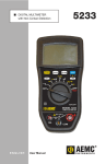
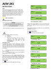
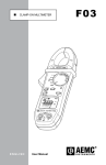
DIGITAL MULTIMETER
with Non-Contact Detection
ENGLISH
User Manual
5231
Statement of Compliance
Chauvin Arnoux®, Inc. d.b.a. AEMC® Instruments
certifies that this instrument has been calibrated
using standards and instruments traceable to
international standards.
We guarantee that at the time of shipping your
instrument has met its published specifications.
An NIST traceable certificate may be
requested at the time of purchase, or obtained
by returning the instrument to our repair and
calibration facility, for a nominal charge.
The recommended calibration interval for this
instrument is 12 months and begins on the date of
receipt by the customer. For recalibration, please
use our calibration services. Refer to our repair
and calibration section at www.aemc.com.
Serial #: _________________________________
Catalog #: 2125.64
Model #: 5231
Please fill in the appropriate date as indicated:
Date Received: __________________________________
Date Calibration Due: ________________________
Chauvin Arnoux®, Inc.
d.b.a AEMC® Instruments
www.aemc.com
Table of Contents
1.INTRODUCTION................................................................................ 3
1.1
1.2
1.3
1.4
International Electrical Symbols.................................................4
Definition of Measurement Categories......................................4
Receiving Your Shipment...........................................................5
Ordering Information..................................................................5
1.4.1 Accessories and Replacement Parts.............................5
2. PRODUCT FEATURES....................................................................... 6
2.1Description.................................................................................6
2.2 Control Features........................................................................7
2.3 Display Features........................................................................8
2.4 Button Functions........................................................................8
2.5 Rotary Functions........................................................................9
3.OPERATION................................................................................... 10
3.1 Turning the Multimeter ON......................................................10
3.2 Turning the Multimeter OFF.....................................................10
3.3 Activating/Deactivating Auto-OFF............................................10
3.4 Auto and Manual Range Selection..........................................10
3.5 Non-Contact Voltage (NCV)..................................................... 11
3.6 Voltage Measurement.............................................................. 11
3.7 Resistance Measurement........................................................12
3.8 Continuity Test.........................................................................13
3.9 Diode Test................................................................................14
3.10Current Measurement Using a Clamp-on Probe.....................15
4.MAINTENANCE.............................................................................. 16
4.1Warning...................................................................................16
4.2 Battery Replacement...............................................................16
4.3Cleaning...................................................................................16
Digital Multimeter Model 5231
1
5.SPECIFICATIONS........................................................................... 17
Repair and Calibration............................................................................19
Technical and Sales Assistance.............................................................19
Limited Warranty....................................................................................20
Warranty Repairs....................................................................................20
2
Digital Multimeter Model 5231
CHAPTER 1
INTRODUCTION
Warning
This device complies with safety standard IEC-61010-1 (Ed
2–2001) for voltages up to 1000V CAT III or 600V CAT IV, at an
altitude below 2000m, indoors, with a pollution level of not more
than 2.
Failure to observe the safety instructions may cause an electric
shock, fire, explosion, or destruction of the instrument and of the
installations.
• Do not use the instrument in an explosive atmosphere or in
the presence of flammable gases or fumes.
• Do not use the instrument on networks of which the voltage
or category exceeds those mentioned.
• Do not exceed the rated maximum voltages and currents
between terminals or with respect to earth/ground.
• Do not use the instrument if it appears to be damaged,
incomplete, or not properly closed.
• Before each use, check the condition of the insulation on the
leads, housing, and accessories. Any element of which the
insulation is deteriorated (even partially) must be set aside for
repair or scrapped.
• Use leads and accessories rated for voltages and categories
at least equal to those of the instrument.
• Observe the environmental conditions of use.
• Do not modify the instrument and do not replace components
with “equivalents”. Repairs and adjustments must be done by
approved qualified personnel.
• Replace the battery as soon as the
symbol appears
on the display unit. Disconnect all leads before opening the
battery compartment cover.
• Use personal protective equipment when conditions require.
• Keep your hands away from unused terminals of the instrument.
• When handling probes or contact tips, keep your fingers
behind the guards.
Digital Multimeter Model 5231
3
1.1
International Electrical Symbols
Signifies that the instrument is protected by double or reinforced insulation.
This symbol on the instrument indicates a WARNING that the operator must
refer to the user manual for instructions before operating the instrument. In
this manual, the symbol preceding instructions indicates that if the instructions
are not followed, bodily injury, installation/sample and/or product damage may
result.
Compliance with the Low Voltage & Electromagnetic Compatibility European
directives (73/23/CEE & 89/336/CEE)
AC – Alternating current
AC or DC – Alternating or direct current
Risk of electric shock. The voltage at the parts marked with this symbol may be
dangerous.
Important instructions to read and understand completely.
Important information to acknowledge.
Ground/Earth symbol
In conformity with WEEE 2002/96/EC
1.2
Definition of Measurement Categories
CAT I: For measurements on circuits not directly connected to the AC
supply wall outlet such as protected secondaries, signal level, and
limited energy circuits.
CAT II: For measurements performed on circuits directly connected to
the electrical distribution system. Examples are measurements on
household appliances or portable tools.
CAT III: For measurements performed in the building installation at the distribution level such as on hardwired equipment in fixed installation and
circuit breakers.
CAT IV: For measurements performed at the primary electrical supply
(<1000V) such as on primary overcurrent protection devices, ripple
control units, or meters.
4
Digital Multimeter Model 5231
1.3
Receiving Your Shipment
Upon receiving your shipment, make sure that the contents are consistent
with the packing list. Notify your distributor of any missing items. If the equipment appears to be damaged, file a claim immediately with the carrier and
notify your distributor at once, giving a detailed description of any damage.
Save the damaged packing container to substantiate your claim.
1.4
Ordering Information
Multimeter Model 5231....................................................... Cat. #2125.64
Includes set of two 5 ft color-coded leads (red/black) with needle tip {1000V CAT IV
15A), soft carrying case and a user manual.
1.4.1 Replacement Parts
Soft Carrying Case .............................................................. Cat. #2121.54
Set of 2, Color-coded 5 ft leads with safety needle tips (2mm)
{1000V CAT IV 15A) ........................................................... Cat. #2140.68
Multifix mounting system...................................................... Cat. #5000.44
Order Accessories and Replacement Parts Directly Online
Check our Storefront at www.aemc.com for availability
Digital Multimeter Model 5231
5
CHAPTER 2
PRODUCT FEATURES
2.1Description
The Model 5231 is a TRMS digital multimeter, specially designed to combine the various functions and measurements of the following electrical
quantities:
• Non-contact detection of presence of network voltage
(NCV function)
• AC voltmeter with low input impedance (voltage measurements
for electricity and electrical engineering)
• AC/DC voltmeter with high input impedance
(voltage measurements for electronics)
• Ohmmeter
• Continuity test with buzzer
• Diode test
• Ammeter (measurement using current clamp-on probe)
6
Digital Multimeter Model 5231
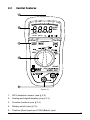
2.2
Control Features
1
0
100
200
300
400
500
2
600
mVA
MkΩ
AC DC
AUTO HOLD
P
3
4
5
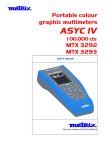
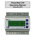
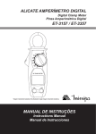
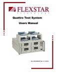
Figure 2-1
1. NCV detection sensor (see § 3.5)
2. Analog and digital display (see § 2.3)
3. Function buttons (see § 2.4)
4. Rotary switch (see § 2.5)
5. Positive (Red) input and COM (Black) input
Digital Multimeter Model 5231
7
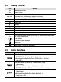
2.3
Display Features
Icon
Function
AC
Alternating Current
DC
Direct Current
AUTO
The Automatic Range symbol indicates that the
instrument will automatically adjust to the correct
measurement range when taking the measurement
HOLD
Freezes the display of the measurement
m
Prefix “mili”
V
Voltage
A
Ampere
M
Prefix “Mega”
k
Prefix “kilo”
W
Ohm
The Overload symbol is displayed when the signal measured exceeds
the range of the device
Low Battery
Continuity Beeper Enabled
Diode Test
Auto Power OFF function activated
P
2.4
Button Functions
Button
Function
• Measurement type selection
NOTE: The DC mode is activated by default
• Activates/Deactivates the Auto-OFF function at start-up
(see § 3.3)
• Allows manual selection of a measurement range
(short press)
• Returns to Auto-Range mode (long press > 2s)
NOTE: Continuity and Diode modes are not Auto-ranging
• Freezes/Unfreezes the display of the measured value
(short press)
• Activates/Deactivates the display backlight
(long press > 2s)
8
Digital Multimeter Model 5231
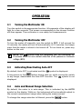
2.5
Rotary Functions
Range
OFF
Function
Powers down the multimeter
Low impedance AC voltage measurement
AC or DC voltage measurement (V)
AC or DC voltage measurement (mV)
Resistance measurement
Continuity test
Diode test
Current measurement with AC or DC clamp, ratio 1mV/A
NCV (Non-contact Voltage) + Partial OFF mode of the multimeter
(NCV function active)
Digital Multimeter Model 5231
9
CHAPTER 3
OPERATION
3.1
Turning the Multimeter ON
Turn the switch to the appropriate function. All segments of the display will
light for a few seconds. The screen corresponding to the chosen function
will then appear. The multimeter is now ready for measurements.
3.2
Turning the Multimeter OFF
To turn the meter off manually, turn the switch to OFF. If left unused for
15 minutes, the meter will turn off automatically. At 14 minutes, five beeps
warn that the meter is about to be turned off. To turn back on, press any
button on the unit.
position does not completely turn the multimeter off.
NOTE: The
It remains active for non-contact detection of the presence of network
voltage (NCV).
3.3
Activating/Deactivating Auto-OFF
By default, Auto-OFF is activated and the
P
symbol is displayed.
A long press on the
button during start-up, while turning the switch
to any range, deactivates the Auto-OFF function. The P symbol is not
displayed.
3.4
Auto and Manual Range Selection
By default, the meter is in auto-range. This is indicated by the AUTO
symbol on the display. While on, the instrument will automatically adjust to
the correct measurement range when taking the measurement.
To change the range selection to Manual, press the
10
button.
Digital Multimeter Model 5231
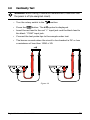
3.5
Non-Contact Voltage (NCV)
• Turn the rotary switch to the NCV position.
• Move the Model 5231 (NCV detection sensor) close to the
potentially live conductor(s) (presence of phase).
If a network voltage of 90V or greater is present, the back-lighting lights up
red, otherwise, it remains off.
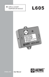
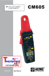
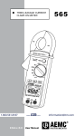
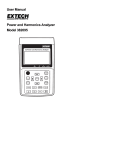
3.6
Voltage Measurement
The Model 5231 measures AC voltage at low input impedance (VLOWZ),
DC and AC voltages.
,
, or
• Set the switch to
device is in AC mode only.
. When set to
or
, select AC or DC by pressing
• For
the meter is in DC mode.
the
. By default
• Insert the red lead to the red “+” input jack and the black lead to
the black “COM” input jack.
• Connect the test probe tips to the sample under test.
Figure 3-1
Digital Multimeter Model 5231
11
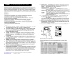
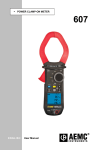
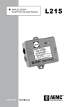
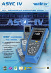
3.7
Resistance Measurement
WARNING: When making a resistance measurement, make sure that
the power is off (de-energized circuit). It is also important that all
capacitors in the measured circuit be fully discharged.
• Turn the rotary switch to the
position.
• Insert the red lead to the red “+” input jack and the black lead to
the black "COM" input jack.
• Connect the test probe tips to the sample under test.
Figure 3-2
12
Digital Multimeter Model 5231
3.8
Continuity Test
WARNING: When making a resistance measurement, make sure that
the power is off (de-energized circuit).
• Turn the rotary switch to the
• Press the
button. The
position.
symbol is displayed.
• Insert the red lead to the red “+” input jack and the black lead to
the black "COM" input jack.
• Connect the test probe tips to the sample under test.
• The buzzer sounds when the circuit to be checked is DC or has
a resistance of less than 100Ω ± 3Ω.
Figure 3-3
Digital Multimeter Model 5231
13
3.9
Diode Test
WARNING: When making a diode measurement, make sure that the
power is off (de-energized circuit).
• Turn the rotary switch to the
• Press the
button twice. The
position.
symbol is displayed.
• Insert the red lead to the red “+” input jack and the black lead to
the black “COM” input jack.
• Connect the test probe tips to the sample under test.
Figure 3-4
14
Digital Multimeter Model 5231
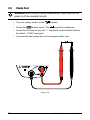
3.10 Current Measurement Using a Clamp-on Probe
• Turn the rotary switch to the
position.
button. By default the
• Select AC or DC by pressing the
meter is in AC mode. Depending on the selection, the screen
displays AC or DC.
• Insert the current probe’s red lead to the red “+” input jack and
the black lead to the black “COM” input jack.
• Clamp the current probe around the current carrying conductor
to be tested.
Figure 3-5
Digital Multimeter Model 5231
15
CHAPTER 4
MAINTENANCE
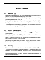
4.1
Warning
• Remove the test leads from any input before opening the case. Do not
operate the instrument without a battery case cover.
• To avoid electrical shock, do not attempt to perform any servicing
unless you are qualified to do so.
• If the meter is not going to be used for a long period of time, take
out the batteries. Do not store the meter in high temperatures or high
humidity.
• To avoid electrical shock and/or damage to the instrument, do not get
water or other foreign agents into the probe.
4.2
Battery Replacement
• The batteries will need to be replaced when the
on the display.
symbol appears
• The meter must be in the OFF position and disconnected from any
circuit or input.
• Using a screwdriver, unscrew the four screws of the battery compartment cover on the back of the housing.
• Replace the old battery with one new 9V battery, observing the polarity.
• Replace the battery compartment cover and tighten the screws.
4.3Cleaning
• Disconnect all leads from the instrument and set the switch to OFF.
• To clean the instrument, wipe the case with a damp cloth and mild
detergent. Do not use abrasives or solvents. Dry thoroughly before
use.
• Do not get water inside the case. This may lead to electrical shock or
damage to the instrument.
16
Digital Multimeter Model 5231
CHAPTER 5
SPECIFICATIONS
Reference Conditions: Accuracy given @ 23°C ± 2°C; Relative Humidity 45 to 75%; Supply Voltage 8.5V ± 0.5V
ELECTRICAL
DC (mVDC)
Resolution
Accuracy (±)
60mV
0.01mV
600mV
0.1mV
1% + 12cts
0.6% + 2cts
Input Impedance
DC (VDC)
Resolution
Accuracy (±)
Input Impedance
10MΩ
600mV
0.1mV
0.6% + 2cts
6V
0.001V
60V
0.01V
0.2% + 2cts
10MΩ
600V
0.1V
1000V*
1V
0.2% + 2cts
AC (mVAC TRMS)
60mV
600mV
Resolution
0.01mV
0.1mV
2% + 12cts
2% + 3cts
2.5% + 12cts
2.5% + 3cts
Accuracy (±)
40 to 60Hz
Accuracy (±)
60Hz to 1kHz
Input Impedance
10MΩ
AC (VAC TRMS)
6V
60V
600V
1000V
Resolution
0.001V
0.01V
0.1V
1V
Accuracy (±)
40 to 60Hz
Accuracy (±)
60Hz to 1kHz
2% + 3cts
2.5% + 3cts
2.5% + 3cts
2.5% + 3cts
Input Impedance
AC (VAC LowZ TRMS)*
Resolution
10MΩ
6V
60V
600V
1000V
0.001V
0.01V
0.1V
1V
Accuracy (±)
40 to 60Hz
Input Impedance
2% + 10cts
270kΩ
* According to safety rules, 1000V range is limited to 600V.
*NOTE: A low input impedance serves to eliminate the effects of interference voltages due to the
supply network, and makes it possible to measure an AC voltage with a minimum of error.
Digital Multimeter Model 5231
17
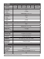
ELECTRICAL
Resistance
600W
6kW
60kW
600kW
6MW
60MW
Resolution
0.1W
0.001kW 0.01kW
0.1kW 0.001MW
0.01MW
Accuracy (±)
2% + 2cts
0.3% + 4cts
0.5% + 20cts
Continuity Test
600W
Resolution
0.1W
Measurement
< 0.35mA
Current
Accuracy (±)
Audible signal < 20W + 3W
Diode Test
2.8V
Resolution
0.001V
Open-circuit
< 2.8V
Voltage
Measurement
< 0.9mA
Current
Accuracy (±)
2% + 5cts
AC/DC Current (with clamp having a ratio of 1mV/1A)
Range
600A
Resolution
0.1A
Accuracy (±)
40Hz to 1kHz; 2.0% + 2cts*
Power
9V (6LR61) alkaline battery
Battery Life
> 100 hours
Auto Power OFF
Automatic shut down after 15 minutes of no use
ENVIRONMENTAL
Operating Temp.
Storage Temp.
Operating RH
Storage RH
32° to 122°F (0° to 50°C)
-4° to 158°F (-20° to 70°C)
≤ 90% at 104°F (40°C)
≤ 50% at 140°F (60°C)
MECHANICAL
Dimension
Weight
Measurement
Acquisition
Bargraph
6.1 x 2.95 x 2.17" (155 x 75 x 55mm)
11 oz (320g) with battery
3 times per second
61 segments, refresh interval 30ms
SAFETY
Safety Rating
Double Insulated
Electro-magnetic
Compatibility
Drop Test
Case Protection
CE
IEC/EN 61010-1, 1000V CAT III, 600V CAT IV; Pollution Degree 2
Yes
EN-61326/A2:2001
1m (in accordance with standard IEC-68-2-32)
IP54 as per EN 60529
Yes
*Not including current clamp sensor accuracy
18
Digital Multimeter Model 5231
Repair and Calibration
To ensure that your instrument meets factory specifications, we recommend
that it be scheduled back to our factory Service Center at one-year intervals
for recalibration, or as required by other standards or internal procedures.
For instrument repair and calibration:
You must contact our Service Center for a Customer Service Authorization
Number (CSA#). This will ensure that when your instrument arrives, it will be
tracked and processed promptly. Please write the CSA# on the outside of the
shipping container. If the instrument is returned for calibration, we need to
know if you want a standard calibration, or a calibration traceable to N.I.S.T.
(Includes calibration certificate plus recorded calibration data).
Ship To:AEMC® Instruments
15 Faraday Drive
Dover, NH 03820 USA
Tel: (800) 945-2362 (Ext. 360)
(603) 749-6434 (Ext. 360)
Fax:(603) 742-2346 or (603) 749-6309
[email protected]
(Or contact your authorized distributor)
Costs for repair, standard calibration, and calibration traceable to N.I.S.T. are
available.
NOTE: You must obtain a CSA# before returning any instrument.
Technical and Sales Assistance
If you are experiencing any technical problems, or require any assistance with
the proper operation or application of your instrument, please call, mail, fax or
e-mail our technical support team:
AEMC® Instruments
200 Foxborough Boulevard
Foxborough, MA 02035 USA
Phone:(800) 343-1391
(508) 698-2115
Fax: (508) 698-2118
[email protected]
www.aemc.com
NOTE: Do not ship Instruments to our Foxborough, MA address.
Digital Multimeter Model 5231
19
Limited Warranty
The Model 5231 is warranted to the owner for a period of one year from the
date of original purchase against defects in manufacture. This limited warranty
is given by AEMC®, not by the distributor from whom it was purchased. This
warranty is void if the unit has been tampered with, abused or if the defect is
related to service not performed by AEMC®.
For full and detailed warranty coverage, go to www.aemc.com. The warranty information is located in our customer service section.
What AEMC® will do:
If a malfunction occurs within the one-year period, you may return the
instrument to us for repair, provided you submit a proof of purchase. AEMC®
will, at its option, repair or replace the faulty material.
Warranty Repairs
What you must do to return an Instrument for Warranty Repair:
First, request a Customer Service Authorization Number (CSA#) by phone
or by fax from our Service Department (see address below), then return the
instrument along with the signed CSA Form. Please write the CSA# on the
outside of the shipping container. Return the instrument, postage or shipment
pre-paid to:
AEMC® Instruments
Service Department
15 Faraday Drive • Dover, NH 03820 USA
Tel: (800) 945-2362 (Ext. 360)
(603) 749-6434 (Ext. 360)
Fax: (603) 742-2346 or (603) 749-6309
Caution: To protect yourself against in-transit loss, we recommend you insure
your returned material.
NOTE: You must obtain a CSA# before returning any instrument.
20
Digital Multimeter Model 5231
02/14
99-MAN 100358 v3
Chauvin Arnoux®, Inc. d.b.a. AEMC® Instruments
15 Faraday Drive • Dover, NH 03820 USA • Phone: (603) 749-6434 • Fax: (603) 742-2346
www.aemc.com