1
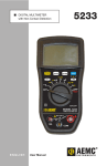
Quattro Test System Users Manual Doc # 98-36389-00 Rev 1.1 11/27/01 Pegasus Quattro Users Manual 1.0 INTRODUCTION ................................................................................................. 4 2.0 HARDWARE DESCRIPTION .................................................................. 4 2.1 MINIMUM HOST SERVER PC REQUIREMENTS .................................................................. 4 2.2 PHYSICAL/ENVIRONMENTAL SPECIFICATIONS ............................................................... 4 2.3 HARDWARE FEATURES........................................................................................................ 5 2.4 TEST ELECTRONICS DESCRIPTION..................................................................................... 5 3.0 INSTALLATION ................................................................................................... 8 3.1 UNPACKING............................................................................................................................ 8 3.2 CONNECTING THE SERVER PC ........................................................................................... 9 3.3 CONNECTING POWER TO THE QUATTRO ......................................................................... 9 3.4 QUATTRO DISK DRIVE CONNECTIONS .............................................................................. 9 3.6 INSTALLING THE HOST SOFTWARE ................................................................................... 9 3.7 BEGINNING TESTING............................................................................................................. 9 4.0 SAFETY INSTRUCTIONS........................................................................ 10 5.0 MAINTENANCE ................................................................................................. 11 5.1 CLEANING INSTRUCTIONS................................................................................................. 11 5.2 CHANGING ADAPTERS ....................................................................................................... 11 5.3 CHANGING THE TEST ELECTRONICS REAR TRAY ................ERROR! BOOKMARK NOT DEFINED. 6.0 TECHNICAL SUPPORT ............................................................................ 12 Doc # 98-36389-00 Rev 1.0 2 Pegasus Quattro Users Manual ADDENDUM A – IDE UDMA-100 HBA .................................................. 13 Doc # 98-36389-00 Rev 1.0 3 Pegasus Quattro Users Manual 1.0 Introduction The Flexstar Quattro test system is a 4-port high performance test system designed specifically for 3.5-, 2.5-, and 1.8-inch storage devices. Up to 4 devices can be tested in each Quattro. In addition, the Quattro can support multiple interface types (up to four). The Flexstar Quattro is controlled by an external host server PC (IBM-PC or compatible), from which the operator can write test programs, start tests, monitor tests in progress, and collect and print test results. Multiple Quattro’s can also be networked to the external server. Flexstar Quattro Features: Seek timing tests: 1 track, 1/3 stroke, maximum track, and average seeks. Independent 5V and 12V voltage margining with Flexstar’s voltage margin card. Voltage is programmable via the test script. Easy software upgrades via the remote boot architecture. Read/ Write testing with variable data patterns. Comprehensive parametric testing. Each test port within the Quattro is a complete Pentium based Single Board Computer (SBC) that controls the port operation and the networking between the host server PC and the Quattro. All test results are held locally at each port and are also periodically sent to the server for backup, report, and database creation. 2.0 Hardware Description The Flexstar Quattro test system consists of a portable enclosure, 4 sets of Flexstar Pegasus test electronics, 4 Flexstar voltage-margining boards, 4 Host Bus Adapters, 4 cable-less anti-vibration fixtures, an external Server PC, and full Client/Server software. 2.1 Minimum Host Server PC Requirements • • • • • • • • IBM or compatible PC running Windows 98, NT 4.0, or Windows 2000. Minimum of 64 MB RAM. Standard Pentium or better at 300 Mhz minimum. 1.44 MB Floppy Drive. 4X or better CD-Rom drive. Hard drive with minimum 50 MB available. Color display (color VGA or SVGA is recommended). 80-column printer (optional). 2.2 Physical/Environmental Specifications Doc # 98-36389-00 Rev 1.0 4 Pegasus Quattro Users Manual SPECIFICATIONS Dimensions Exterior 17.5"W x 20"D x 13.5"H (44.5 cm W x 50.8 cm D x 34.3 cm H) 300 CFM Internal Air Flow Power Requirements 115 VAC 230 VAC Shipping Weight (Quattro) Shipping Weight (Server) Drive Capacity 1.8 inch to 3.5 inch 100-125 VAC, 1PH, 50/60 Hz, 3 amps 208-240 VAC, 1PH, 50/60 Hz, 2 amps 51 Lbs. (23 kgs) 71 Lbs. (32.2 kgs) 4 Flexstar Technology Inc. reserves the right to change, modify or revise specifications at any time without notification to user. In addition the Company is not responsible for any harm to personal damage to equipment due to improper connection or routing of electrical and plumbing. 2.3 Hardware Features HARDWARE FEATURES BENEFITS Inexpensive, easy to change adapters for IDE, SCSI, Fibre Channel, 1394, etc. Cost effective multi-interface testing, inexpensive upgrade path to future interfaces. High performance SBC provides maximum throughput capability for today’s high-speed interfaces. Fastest sustained data rate available guarantees effectiveness with current and future drives. Software generated Sector unique random data and data compare capability. Diskless SBC’s boot most current software from the Server. Fastest, most reliable method of assuring data and device integrity. Quick and easy upgrades and enhancements. Voltage margining, current measurement, and power cycling. Provides essential power testing and profiling for today’s low power drives. 2.4 Test Electronics Description The test electronics used for each port (also referred to as a client) is based on a small form factor Single Board Computer (SBC). The SBC comes standard with a 633 Mhz Celeron processor, 32 MB of RAM memory, and various integrated peripheral controller chips that make up a fully functional PC including, video, networking, PCI slot, on-board IDE, etc. In addition to the SBC, the assembly contains a power module that provides fixed power for the SBC and variable power for the devices under test. Depending on the interface type supported, the device controller may either be the on-board IDE controller, on-board SCSI III controller, or a PCI add-on board. This architecture allows for a variety of possible interfaces including IDE, ATAPI, SCSI, FCA, 1394, serial ATA, etc. Doc # 98-36389-00 Rev 1.0 5 Pegasus Quattro Users Manual Therefore, each test electronics assembly is a complete diskless PC subsystem that is entirely self contained and networks to the server PC. Since the subsystem is diskless, each client will boot it’s operating system, application files, and support files from the remote server. Flexstar provides a remote boot manager for the Microsoft Windows operating systems (all except Windows 95). SBC Features - Accepts Intel Celeron or Pentium III socket 370 CPU’s up to 850 MHz. 32-bit PCI-bus SVGA controller supports 800x600 x 256 colors for CRT displays. 10/100 Ethernet interface. 2 serial ports and one parallel port. USB interface, PCI slot, and PC/104 Plus (PCI) connectors for flexible expansion capabilities. Watchdog timer with jumper less selection. SBC Specifications and Standard SBC Functions - CPU: Intel Celeron up to 850 MHz. BIOS: AWARD 128KB Flash bios, supports Plug & Play, APM. Remote boot code built into the BIOS ROM. Chipset: Intel 810. Green function: APM 1.1 compliant RAM: One DIMM socket supports up to 256 MB DRAM. Enhanced IDE interface: Supports 1 IDE UDMA-66 device. FDD interface: Supports up two FDDs ( 360k/1.2m/720k/1.44B/2.88MB) Parallel port: One parallel port, supports SPP/EPP/ECP parallel mode Serial port: Two serial ports (COM1 and COM2). Watchdog timer: 63-level interval from 1 to 63 seconds. Generates system reset or IRQ15. Jumper less selection and software enable/disabled. PS/2 keyboard/mouse connector. USB interface: Two USB connectors with fuse protection. Complaint with USB Spec. REV. 1.0 (option) PC/104 Plus expansion: PCI compliant with PC/104 type stackable connector. PCI bus expansion: One 32-bit / 33 Mhz PCI bus expansion slot. PCI SVGA interface - Chipset: Intel 810 Display type: Supports CRT and compatible flat panels up to 800x600 resolution with 256 colors. PCI Bus Ethernet Interface - Chipset: RealTEK RTL8139 PCI local bus Ethernet controller Ethernet Interface: 10/100 BaseT interfaces. Includes software drivers & boot ROM Mechanical and environmental - Operating temperature: 5 to 40 C (40 to 105 F) Size: 11.0” (280 mm) X 4.50” (114 mm) Weight: 0.32 kg (1.7 lbs.) Doc # 98-36389-00 Rev 1.0 6 Pegasus Quattro Users Manual Programmable Power Module Power for the SBC and the devices being tested is generated by a post regulator card located near each SBC and is connected to the SBC via an RS-232 cable. The power module accepts a 15V DC input and provides two fixed voltage outputs (+5V & +12V) for the SBC and two programmable output channels for the drive under test (DUT): - Fixed 5V +/- 2% @ 7.5 amps for SBC power. Fixed 12V +/- 2% @ 1 amp for SBC power. Variable 5V output @ 3.5 amps for device under test. Range = 0 to 7.5V in 1.8 mv steps. Variable 12V output @ 3.5 amps for device under test. Range = 0 to 15V in 3.6 mv steps. Bulk Power Supplies The Quattro test system utilizes a single 15V bulk power supply, which provide power for each port’s post regulator. The power supply is manufactured by ASTEC and requires 100 to 250 VAC 50/60 Hz input and provides 15V out at 23 amps (350 W). Doc # 98-36389-00 Rev 1.0 7 Pegasus Quattro Users Manual 3.0 Installation IMPORTANT INSTRUCTIONS -- READ BEFORE UNPACKING 3.1 Unpacking When you receive your Flexstar Quattro, take care to follow these unpacking instructions otherwise damage may occur to the system. 1. Remove the Quattro and all other contents from the shipping container. 2. Remove plastic wrap surrounding the Quattro. 3. Insure that there is no visible damage to the exterior of the Quattro. The shipping carton should contain the following items. Before you proceed, make sure you have everything on this list. If anything is missing, call Flexstar Customer Support at (510) 4400170. (1) (1) (1) (1) (1) (1) (1) Flexstar Quattro test system. Optional Server PC. Ethernet Cable Kit. Flexstar Client/Server software CD. Flexstar Quattro Users Manual (this document) Host Software User's Manual. FBoot Users Manual. Location and Connections Once the Quattro is unpacked it may be placed on a desktop or cart. The unit should have a working area of 18”H X 30”W X 24”D. This will allow servicing of the unit. The unit should be operated within a temperature range of 5o C to 40o C, and no greater than 90% relative humidity non-condensing. Doc # 98-36389-00 Rev 1.0 8 Pegasus Quattro Users Manual 3.2 Connecting the Server PC The Server PC (if supplied), is connected as follows: 1) Connect keyboard, mouse, printer, and etc. to the PC. 2) Connect a straight through Ethernet cable from the NIC card in the Server PC to the Ethernet RJ-45 jack on the rear of the Quattro chassis. 3.3 Connecting Power to the Quattro The electrical connection of the Quattro is made via a standard 3 prong AC cable and requires from 100 to 130 VAC 50 to 60 Hz at 4 amps maximum. 3.4 Quattro Disk Drive Connections Located at the front of the Flexstar Quattro are the power and interface connections needed for the drive or drives under test. Depending on your configuration, these connections will either be an auto-eject mechanism (standard) or a pair of cables (one for the power and one for the drive interface) for each slot. Be sure to properly orient pin 1 on the drive with pin 1 on the connector whenever connecting a drive to the tester. 3.6 Installing the Host Software 1. See the Pegasus Host Software User Manual for installation directions. 3.7 Beginning Testing You are now ready to start testing. Turn on your Server PC and ensure that both the FBoot software and Host software are functioning properly. Please refer to your Flexstar Host Software Guide and FBoot User’s Guide for specific instructions on the use and operation of the host software and remote booting setup. After you have verified that the software is functioning, turn on the Quattro with the switches located on the front and rear panels. Doc # 98-36389-00 Rev 1.0 9 Pegasus Quattro Users Manual 4.0 Safety Instructions Listed below are other precautions that should be taken to ensure your safety as well as the proper operation of your test system. 1. Do not place this product on an unstable cart, stand, or table. The product may fall, causing serious injury to the operator or damage to the product. 2. The air-cooling fan at the rear of the cabinet, and slots on the front are provided for ventilation. To ensure reliable operation of this product and to protect it from overheating, do not block or cover these openings. 3. Never push objects of any kind into this product through the slots as they may touch dangerous voltage points or short out parts that could result in a risk of fire or electrical shock. 4. Never spill liquid of any kind on the product. 5. Do not allow anything to rest on the power cord. Do not locate the product where the power cord will be walked on. 6. Do not under any circumstances place anything in, over, or through the finger guards covering the fans installed in the product. 7. Never, under any circumstances, open the unit cover while the power to the unit is on. High voltage in the enclosure could cause injury or death. 8. Read all of these instructions and save them for later reference. Doc # 98-36389-00 Rev 1.0 10 Pegasus Quattro Users Manual 5.0 Maintenance External Maintenance check (suggested every 30 days) 1) Check that the DC cooling fan located on the rear panel of the unit is functional and is moving air out of the enclosure. Also check for obstructions and dust build-up around the fan area and around any air inlets. 2) Check for wear on the vibration fixture located on the top cover. Check for signs of wear on the sub-adapter drive I/O connector. Replace sub-adapter if necessary. Note: The sub-adapter connector may only be reliable for a limited number of insertions. The reliability depends on the connector type and number of pins. 3) Check for wear or pin spreading on the 4 pin DC connector. Internal Maintenance Check (suggested every 90 days) A qualified service technician should perform the internal maintenance check, as the possibility of electrical shock does exist. 1) Remove the A.C. cord from the receptacle at the rear of the enclosure. 2) Remove the top cover of the enclosure and check that the SBC CPU cooling fans are operating normally. Replace the defective cooling fan if necessary. 3) Check for excessive dust build-up around the CPU and cooling fan. Clean if necessary. 4) Check to see that all PCI adapters are seated in the PCI connector. 5) Replace the top cover. 5.1 Cleaning Instructions EXTERIOR Keep Cabinet free of dust and dirt. Clean the exterior of the Cabinet with a soft damp cloth. DO NOT USE ABRASIVE CLEANSER. Inspect the cooling fans at the rear of the unit for proper operation and build up of dust or other restrictions around the finger guards. 5.2 Changing Host Bus Adapters To change a faulty adapter, or to change to a new type of adapter, follow these steps. 1) Turn system power off. 2) Loosen the thumb screws on the front of the unit and slide out the electronics tray. 3) The host adapter bracket is attached to a right angle bracket that is part of the client SBC mounting. Remove the screw that holds the adapter bracket in place and remove the adapter from the PCI riser PCB. 4) Reverse this process to add a new adapter to the system. Doc # 98-36389-00 Rev 1.0 11 Pegasus Quattro Users Manual 6.0 Technical Support Should a problem arise with the Quattro, please contact Flexstar technical support at (510) 4400170. If it is determined that components of the tester need to be repaired or replaced, use the instructions in section 5.2 to remove the faulty components. Flexstar Technology 47323 Warm Springs Boulevard Fremont, CA 94539 (510) 440-0170 Fax (510) 440-0177 Email: [email protected] www.flexstar.com Doc # 98-36389-00 Rev 1.0 12 Pegasus Quattro Users Manual Addendum A – IDE UDMA-100 HBA Description The Flexstar UDMA 100 card is a bus master Ultra DMA PCI-IDE/ATA disk drive controller capable of Ultra DMA transfer rates up to 100 Mb/Sec. The card also supports all legacy modes: PIO, Multi-Word DMA, Etc. In addition this design also incorporates full tri-state control over all interface signals for use in test systems and hot plug designs. The controller is designed around the CMD 649 UDMA-100 controller chip and contains circuitry to support both primary and secondary channels. Features • 2 independent IDE/ATA channels can support up to 4 devices. • Full tri-state control over all drive interface signals (enabled by drive 5V) to enable hot plugging and power cycle testing. • 128 byte FIFO improves burst transfer efficiency. • Support for all PIO and Multi-Word DMA transfer modes. • CRC support for UDMA protocol. • 32-bit 33 MHz PCI interface. • Supports transfer rates on both channels up to 100 MB/Sec. • ATA/ATAPI-5 specification compliant. • Compact small form factor size: 6.25” L x 2.7” H. • 3.3V operation with 5V tolerant I/O. Installation Installation of the Flexstar UDMAxxx card is as follows: 1) Set the option jumpers to the default settings noted below and in figure 1. 2) Install the card in the system and secure the bracket using a #6-32 screw. 3) Connect a 80-pin high-density (18” maximum length) cable to the PRIMARY and/or SECONDARY connectors (J3 & J4). 4) Connect the drive power tri-state control cable to J5 and J8 – make sure the polarity is correct. J1 Option Jumper Settings Jumper Default Setting JP0 OUT JP1 JP2 JP3 JP4 JP6 JP7 JP8 OUT IN OUT IN IN IN IN Doc # 98-36389-00 Rev 1.0 Description Sets the controller to appear as IDE device in PCI Bios. Native mode capable (use IRQ14, base adrs=0). Native mode. Enable primary IDE channel. Enable secondary channel. Disable IDE cycles after reset. Don’t overwrite the Subsystem ID in PCI config regs. No EPROM support. 13 Pegasus Quattro Users Manual J2 Interrupt Setting The default setting is INTA. This routes the IRQ14 from the CMD chip to PCI INTA. J6, J7 Primary and Secondary Port Tri-state Control Jumpers These jumpers should be installed in the TS EXT position if external tri-state control is to be used (standard for Flexstar test systems). Otherwise the jumper should be installed in the LOWZ position, which disables tri-state control (output buffers are in the LOW-Z state always). Note: When using external tri-state control, a control cable must be installed at J5 and J8, which provides +5V from the drive 5V power. When the drive is off (5V=0), the tri-state buffers will be in a high impedance state. When the drive is powered on (5V >= 2.5V), the tri-state buffers will be in the low impedance state. Figure 1. Flexstar UDMAxxx Card Doc # 98-36389-00 Rev 1.0 14 Pegasus Quattro Users Manual Addendum Addendum A - IDE UDMA-100 HBA .................................................................................................... 13 Cleaning Instructions Exterior..................................................................................................................................................... 11 Interior...................................................................................................................................................... 11 Hardware Description..................................................................................................................................... 4 Hardware Features...................................................................................................................................... 5 Minimum Host Server PC Requirements ................................................................................................... 4 Physical/Environmental Specifications ...................................................................................................... 5 Test Electronics Description....................................................................................................................... 5 Installation ...................................................................................................................................................... 8 Beginning Testing ...................................................................................................................................... 9 Connecting Power to the Quattro ............................................................................................................... 9 Connecting the Server PC .......................................................................................................................... 9 Disk Drive Connections ............................................................................................................................. 9 Installing the Host Software ....................................................................................................................... 9 Unpacking .................................................................................................................................................. 8 Introduction .................................................................................................................................................... 4 Maintenance ................................................................................................................................................. 11 Changing Adapters ................................................................................................................................... 11 Changing the Test Electronics Rear Tray................................................................................................. 11 Cleaning Instructions................................................................................................................................ 11 Safety Instructions........................................................................................................................................ 10 Doc # 98-36389-00 Rev 1.0 15