1
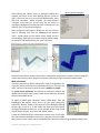
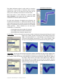
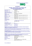
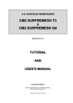
MESHING
FEMdesigner AD Explorer
What is a mesh?
A mesh is a group of interconnected finite elements joined together at
nodes that represents the shape of continuous geometry, including both
the external surface and the interior volume. In the case of FEMdesigner
AD this geometry is the Alibre/Geomagic Design 3D CAD model. A mesh
can also be thought of as the CAD model being “chopped up” into
discrete pieces (finite elements) that are connected together. Because
these elements are geometrically quite simple, the equations associated
with each individual element are relatively simple, so that when the
mesh is assembled into a matrix of equations, we can solve complex
geometries by solving a large number of simple equations.
Finite Element Types
In FEMdesigner AD we use the versatile tetrahedral element type, also
known as a “tet” in the language of FEA. A tetrahedron is simply a foursided pyramid with triangular faces, as shown in the diagram here.
Tetrahedral Element
with Nodes
Part Mesh Dialog Box
The simplest type of tet element is linear, i.e.
having linear edges and only end nodes, shown as
black dots in the diagram. In FEMdesigner AD,
the default element type is a parabolic tet, whose
edges are curved 2nd-order quadratic segments
with mid-side nodes added, shown here in red.
These higher order elements can be significantly
more accurate than their linear counterparts.
FEMdesigner AD can also create linear tet meshes
for analysis, which have the advantage of being
much faster to solve, and in some cases can be as
accurate as parabolic elements.
There are other types of specialty elements used
in FEA that are not currently available in
FEMdesigner AD, such as bricks, shells, plates,
and others. These types of elements are planned for future releases.
Creating a Mesh
Creating a mesh from a part or assembly with FEMdesigner AD is very
straightforward. Using the default settings, a mesh is created literally at the
touch of a button, and the mesh can also be easily customized to the
requirements of your analysis.
Selecting “Build Mesh” from the FEMdesigner AD Explorer menu (shown in
yellow rectangle above) will display the part mesh dialog box, shown at left.
Immediately selecting the “MESH” button in the part mesh dialog box will create
a mesh of the current part or assembly using default values. These default
values are calculated to create a mesh with the fewest elements (i.e. fastest
calculation time) that will also produce accurate results.
Copyright © 2014 FEMdesigner Ltd. All Rights Reserved
After selecting the “MESH” button, a dialog box displays the
progress and status of the mesh building process, shown at
right. If there are any errors, they will be displayed here, along
with their resolution. When complete, the dialog displays
“Finished” as the last line, and the user has the option of
scrolling the dialog text to review the mesh creation process, or
selecting “Exit” to dismiss the dialog box.
Mesh Progress Dialog Box
After exiting the mesh progress dialog box, we can view the
mesh by selecting “Plot” from the FEMdesigner AD explorer
menu. Shown below are the Alibre Design model and the
corresponding mesh that was created using the default values
for the mesh, and displayed using the “plot” command.
Notice that the mesh is relatively coarse when compared to the geometric features, but every edge has
at least two elements, which will give us accurate results for most general analysis requirements.
Mesh refinement
If analysis requirements dictate that specific areas of the geometry are
of greater interest and require more detailed results, we can refine the
mesh. There are two ways to refine the mesh: globally and locally.
For global mesh refinement, we indicate the maximum element size
allowed for the entire mesh, and the mesh will be built with elements
that do not exceed that size.
To specify a global mesh refinement, select “Build Mesh” from the
FEMdesigner AD explorer menu, and in the part mesh dialog box,
expand the “Bounds” section in the lower part of the dialog by selecting
the plus sign (+) next to it. In the “upper size” data entry field, specify
the largest allowable element size. In this example we are using a value
of 0.05 (shown at right). Then select the “MESH” button.
A mesh will automatically be created with elements that are no larger
than the maximum allowable size entered. Using the same part shown
above, we can create a mesh that is considerably more dense than when using the default element size.
Copyright © 2014 FEMdesigner Ltd. All Rights Reserved
This global refinement option is rarely used, as it tends to
create quite a large number of elements, which increases
solution time, and it is not often that a fine mesh over an
entire part or assembly is necessary for accurate results.
Global Mesh Refinement
Much more often, if mesh refinement is necessary, local
mesh refinement is the option that will produce the best
combination of solution speed and accuracy.
For local mesh refinement, like global mesh refinement, we
increase the mesh density, i.e. reduce the element size, by
either requiring a minimum number of elements along model
edges, or by specifying a maximum element size for selected
model geometry. These methods can be used either
individually or in combination:
-
Curved edges (minimum number of elements)
Linear edges (minimum number of elements)
Selected geometry (maximum element size)
Curved edges: the user can specify the minimum number of elements to be generated along all curved
edges of the model, thereby increasing the mesh density along those
edges. The system default is 2. In this example, in the “Bounds” section
of the part mesh dialog, we entered ‘6’ in the “curve elements” field,
forcing all curved edges to have at least 6 elements along their length.
Default
curve elements = 6
Linear edges: the user can also specify the minimum number of elements to span all linear edges of the
model. The system default is 2. In this example we entered ‘5’ into the data field “edge elements” in
the “Bounds” section of the part mesh dialog box to increase the mesh density along all linear edges of
the model. Notice that for the longer linear edges of the model, the
mesh density does not change very much from the default, because
larger elements can be used to satisfy the required minimum number of
elements along these longer edges.
Default
Copyright © 2014 FEMdesigner Ltd. All Rights Reserved
edge elements = 5
Selected geometry: the user can also specify the maximum element size for a particular geometry
selection. In Example 1 below, we selected a square end face (0.25 x 0.25) and assigned a maximum
element size of 0.05. To refine the mesh in this way, select the desired geometry, then enter the largest
Selected Geometry – Example 1
allowable element size for the selected geometry in the “Enter size” data entry field in the upper section
“Set local element sizes (optional)” of the part mesh dialog box. Then select APPLY. As in the other
examples, this higher mesh density will be enforced for the selected geometry, and the element sizes
will gradually blend into the elements created at the default or other values.
Selected Geometry – Example 2
As shown in Example 2, we can select multiple faces and assign a different element size to each face. To
do this, select the geometry (multiple items can be selected), enter the desired element size, and select
APPLY. Repeat for each geometry selection requiring a different element size as needed for analysis.
Linear vs. Parabolic Elements
As noted previously, parabolic elements are more accurate
than linear elements. Knowing this, when do we use linear
elements? Actually, there are several situations where linear
elements are preferable for their speed, and in some cases
they can be just as accurate as their parabolic counterparts.
In the beginning of the design cycle, use linear elements:
Generally, linear elements can be used when speed is just as
important as, or perhaps even more important than accuracy.
Because analysis is an iterative process used to help the
designer create a design that meets strength, weight, thermal,
and other requirements, the initial stages of analysis are often “first cut” and “quick and dirty” analyses
to get these design modifications going in the right direction. For this part of the analysis cycle, linear
elements can be preferable for their speed – analyses and design modifications can be made quickly,
Copyright © 2014 FEMdesigner Ltd. All Rights Reserved
which can significantly reduce design/analysis cycle time. As the design becomes more refined, we can
switch to parabolic elements and mesh refinements to target more subtle and localized changes while
achieving the required accuracy. Caveat: the simpler and smaller your designs, the less this is true, i.e.
the speed advantage of linear elements is more pronounced with larger and more complex designs.
For thermal-only analysis, use linear elements: If you are calculating thermal results, a linear mesh can
be considered as accurate as a parabolic mesh because the math involved in the thermal solution can be
modeled quite accurately by linear elements, as opposed to stress, which is mathematically one level of
differentiation more complex than temperature or displacement. So there is an accuracy advantage
with higher order elements for stress calculations. Caveat: if you will be using your thermal results to
calculate mechanical stress due to thermal expansion/contraction, parabolic elements should be used for
thermal results because the same mesh must be used for both the thermal and the stress calculations.
Tips for Creating “Good” Meshes
With FEA, there is always a trade-off between speed and accuracy. The goal is to arrive as quickly as
possible at a solution that meets accuracy requirements. We have examined some ways to do this
above, i.e. refining the mesh locally to get accuracy in areas that are more important, while leaving the
mesh more coarse in areas that are less important, and using linear elements where appropriate.
Meshing Challenges
While FEMdesigner AD’s automated meshing is generally very good at creating meshes that produce
highly accurate results with a mesh that is optimized for shortest calculation times, there are situations
that can pose problems for a mesher that uses only tetrahedral elements. Generally these are parts
with a high aspect ratios (long, thin parts), or more commonly, large, thin-walled parts.
If we take, for example, a length of large-diameter pipe, or perhaps a storage tank where the wall
thickness of the pipe or tank is much smaller than the diameter or length, the default meshing
parameters will sometimes not produce a “good” mesh. In fact in certain cases, the default parameters
can result in a failed mesh attempt. These are rare cases, and the fix is relatively simple: we simply
adjust the meshing parameters to accommodate the type of part we are meshing.
Let’s examine a length of pipe with an inside diameter of 48 inches, a wall thickness of ½ inch, and a
length of 10 feet:
Using default parameters, the mesher fails and displays the error messages shown in the image of the
mesher dialog box above. The reason for this is that the mesher starts with a maximum allowable
element size that is calculated based on the size of the bounding box of the part, which in this case is
Copyright © 2014 FEMdesigner Ltd. All Rights Reserved
quite large when compared to the wall thickness of the part. With this starting value for element size,
the mesher is unable to converge to a solution for the surface mesh.
The fix for large, thin-walled parts like this is to force the mesher to start with a smaller maximum
element size so that the mesher will converge to a solution. Recalling the global mesh refinement
above, we can adjust the maximum allowable element size (upper size) in the Bounds section of the
Mesh dialog. The default calculated for this part (based on the size of the bounding box) is 34.6428, as
shown below. A good rule of thumb for large, thin-walled parts is to divide that number by 4 and
recalculate the mesh. For example, when we enter “9” for the upper size, a good mesh is calculated
quickly. Of course this upper size can be made smaller to obtain a finer mesh if necessary, or if the mesh
attempt fails again, we can decrement the upper size until we generate a good mesh.
upper size = 9
Meshing Anomalies: Holes
In some rare cases, we have found that meshes created on the inside cylindrical faces of holes will
sometimes use a node value from the other side of the hole. We are certainly investigating this and will
be incorporating a fix in the code as soon as possible, but we aren’t going to pretend it doesn’t happen,
even if it is rare, and we want to make sure our users can work around this in the meantime.
The fix, as above, is a simple mesh refinement. By applying a local element size to the inside cylindrical
surface, we force the mesher to recalculate the mesh in that area, and generate a good mesh. Select
the cylindrical face and apply a local element size of approximately (radius of hole)/3. This will not
increase the mesh density significantly, but it will force the mesher to recalculate the mesh in this area.
In the example shown above, there is an obvious anomaly in the mesh for one of the holes. We simply
assign a local element size as shown, re-run the mesher, and obtain a good mesh.
Copyright © 2014 FEMdesigner Ltd. All Rights Reserved
Rules of Thumb for “Good” Meshes
In summary, meshing is the way we represent continuous model geometry with finite elements. To
balance the conflicting goals of speed and accuracy, and also to be able to generate a good mesh even
when the geometry is challenging, here are a few rules of thumb for generating meshes with
FEMdesigner AD:
-
Use the default mesh parameters whenever you can, they will usually create an accurate mesh
with fast solution times
Where more accuracy is desired, use local mesh refinements in areas of interest
Use global mesh refinements only when necessary, as they can create large meshes and longer
solution times
Use linear elements early in the design/analysis cycle, switching to parabolic when better
accuracy is required
Use linear elements for thermal-only analysis (not thermal stress)
For mesher failure or mesh anomalies, refine the mesh appropriately and re-run the mesher
Copyright © 2014 FEMdesigner Ltd. All Rights Reserved