1
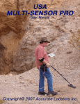
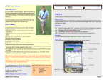
Depth and type of target govern the type of tool (detector) needed.
At ACCURATE LOCATORS we offer a wide variety of Imagers.
Thank you for purchasing the PINPOINTER PRO
Table of Contents
Introduction and Packing Contents
2
Getting Started
3
PC Set Up
4
Ground Balancing and Scan Methods
5
Scan Methods and Samples
6
Scan Samples
7
Scan Samples
8
Scan Sample and Pinpointer Pro Options
9
Trouble shooting
10
Warranty
11
Accurate Locators Inc.
1383 2nd Ave. Gold Hill, Oregon 97525
Sales Phone No. (USA & Canada) 866-369-1975 or 541-326-4169
International Sales: 01-541-326-4169 Fax: 775-537-6613
e-mail: [email protected]
Website: www.accuratelocators.com
1
PINPOINTER PRO
The PINPOINTER PRO is a state of the art ground imaging instrument that is well suited for both
the utility locator as well as the professional treasure hunter. It has advanced software which
makes operating the unit and data analysis much simpler than other brands available. The
software renders color representation of the surveyed field, as well as in real time. Added as an
additional imager the PINPOINTER PRO can detect the strongest and weakest point of a target
as well as estimating depth, and can penetrate deeper than most other instruments.
This unit can be used with all USA IMAGER SYSTEMS.
The PINPOINTER PRO is a stand alone unit. The control unit is in the antenna, just plug the USB
cable into the computer, plug the other end into the antenna, open the program and you are
ready to go.
The system comes complete with all you need to survey with confidence and accuracy, and is
available with optional equipment for even more convenient operations.
Packing Contents
* Antenna with built-in Control Unit
* Carrying case for antenna
* Cable for connecting antenna and computer
* Tablet Personal Computer (complete with Windows XP, built in WI-FI and Bluetooth)
* Carrying case for computer (can be belt mounted)
Computer
Optional equipment (details on page 11) includes:
* PC video gasses
* GPS systems
ULTRA MOBILE PC
Antenna Bag
Cord
Computer Case
Antenna
2
It's that simple
Getting Started
Quick Start Pinpointer Pro
PC Brand Subject to Change Without Notice
Training
Training is available with the purchase of a unit, and one hour of technical assistance is
offered after purchase.
Software
The software included with the PINPOINTER PRO is installed and ready to go to work for
you.
Quick Start Procedure
1. With the cable supplied plug the USB end into PC USB port (left edge view) then plug
the other end of the cord into antenna
2. Turn on UMPC or laptop computer (left edge view) and start software
3. Allow a few moments for the programs to communicate with each other
A. Click on recommended resolution of 800X480 (if not preset)
B. Using stick point button or stylus move over Pinpoint file and left click (front view)
4. When it’s ready, click Connect then click Start, now you may begin scanning
5. Keep antenna pointing down (vertical) as close to the ground as possible and in the
same direction, without rotating the antenna for best results.
Front view
Mouse right click
Mouse left click
Stick point (Mouse or touch pad)
Front Edge View
Stylus Compartment (pen)
Docking Port
Software Keyboard
Launch Pad
Left Edge View
Right Edge View
...
DC In
WLAN On/Off
...
SAS
..
USB Port
USB Port
Audio In/Out
Volume Up/Down
Power Hold
Detailed PC information supplied on pages 4 and 5
3
PC Set Up
Green - Background
Targets (common ground)
Blue - Weak Target
(void, cave or tunnel)
Red - Strong Targets
(metal chest, metal pipes)
Scans / Second
Scans per second is default set at 5, for normal walking speed of scan (how fast you travel).
The highest setting of 10 would be for running or vehicle speed scanning.
High and Low Value
The high and low value is default set at 15 and -15 and can be changed for the strength of the
target. The value settings are: Low = 10/-10, Med. = 25/-25 and High = 50/-50, the arrow
boxes next to the value squares fine tune to precise numbers. Clicking on the default value
returns the values to the default settings. For the weaker targets the high and low settings
(under options) can be decreased to detect the weaker targets (example 10/-10 or 5/-5 for
even weaker targets). The stronger targets dictate raising the values to separate the
surrounding background from the target.
The high and low data readings capture the highest or lowest signals for that scan. While
scanning a small difference in the numbers can mean a target is detected.
Current
The current reading is where the antenna is reading at the time. The current (current signal
strength) reading can assist in relocating the highest / lowest reading point (or target). The
highest and lowest numbers captured as data readings can be matched with the current
reading to relocate or confirm target. The color bar is indicating the current reading also.
Monitor Indicators
The colors indicate: Green as ground or background targets. Blue indicates weak targets
such as voids, tunnels, caves and possible non-ferrous metals. Yellow / Orange indicates
medium targets or the edge of a strong target. Red is a strong target such as ferrous metals. If
a weak target isn't indicated in red on the monitor then lowering the values will result in
showing the target colors.
6
STATUS BAR
Indicates the connected or not connected status of the antenna.
Ground Balancing and Scan Method
Ground Balancing
Pause and without turning the antenna (clockwise or counter clockwise) set PC at "0" (click
on start) over ground that is known not to have a target, this is referred to as ground
balancing. You can repeat the Ground Balancing during a scan to clear past high and low
readings (but ground balancing starts over).
Mark a starting point on the ground far enough from the suspected target to have sufficient
background readings and proceed in a straight line toward desired point (past target area).
It's recommended laying out a grid marked on the ground for an organized accurate scan
(with a GPS the grid can be laid out on it). To continue a grid scan return to the beginning
point and move to the right of that point (about 2 ft. or less increments) and repeat the scan
once again. Repeat this technique as many times as desired. If possible scan south to north
for best results. Live mode is real time, showing what you are scanning currently and is not in
the memory of the PC. Antenna is always best to be pointed in the same direction, vertical
and as close to the ground as possible.
For depth estimation mark the ground over target (largest Number) then walk away from
target until you get "0" reading. Then measure distance to target, that distance will be
approximate depth. Repeat several times at different angles of approach to affirm depth
estimation.
7
Scan Method and Samples
When detecting hallow objects or objects with disturbed ground you can read both negative
and positive numbers as it can detect the metal or the void, also the direction (north, south) the
antenna is facing can influence the numbers. The indicating numbers may not be large, it is the
difference in numbers that is the indicator. The monitor will show red when detecting a metallic
object and blue will be a void (a negative or milligauss reading) when the values are set
correctly. When a target is located mark the ground and approach the target area from different
angles and try to repeat the scan results to confirm target location (this will assist in depth of
target equation also).
Barrel buried 6 ft. deep
14'
-2
1
-1
1
14'
12'
2
2
3
3
12'
10'
2
4
4
4
10'
8'
3
6
5
5
8'
6'
2
6
5
5
6'
4'
3
4
4
4
4'
2'
1
2
3
3
2'
0'
0
0
0
0
0'
0'
2'
4'
6'
For depth estimation mark the ground over target (largest Number) then walk away from target
until you get "0" reading. Then measure distance to target, that distance will be approximate
depth. Repeat several times at different angles of approach to affirm depth estimation.
8
Scan Samples Using the Pinpointer Pro
Scans Performed in the Dry Desert Climate at Walking Speed
South
to North
Travel
0'
2'
4'
6'
8'
10'
12'
0
-1 / 1
+3
+7
+4
+2
0
Tire Rim Buried 6 ft. Deep
North
to South
Travel
0'
2'
4'
6'
8'
10'
12'
0
+1
0
-3
-1 / +1
+1
0
PVC Buried 2 ft. Deep
North
to South
Travel
0'
2'
4'
6'
8'
0
+1
-13
-1
-1
Note can read +13 it
depends on orientation of the object
(pointing north or south)
Rebar 3 in. deep in concrete
9
Scan Samples Using the Pinpointer Pro
Scans Performed in the Dry Desert Climate at Walking Speed
South
to North
Travel
0'
2'
4'
6'
8'
10'
12'
0
+1
+3
+7
+2
+2
-1
Copper, Aluminum and Other Metals Buried 5 ft. Deep
North
to South
Travel
0'
2'
4'
6'
8'
10'
12'
0
+1 / -1
+3
+7
+2
+1
+1
Copper, Aluminum and Other Metals Buried 5 ft. Deep
North
to South
Travel
0'
2'
4'
6'
8'
0
+2
+9
-1
-1 / +1
Hammer Head Buried below concrete floor
10
Scan Samples Using the Pinpointer Pro
Scans Performed in the Dry Desert Climate at Walking Speed
North
to South
Travel
0'
2'
4'
6'
8'
10'
12'
0
-1
-4
-17 / +7
-6 / +2
-2 / +2
-2
Ten Pounds of Gold and Silver Buried 5 ft. Deep in the Back Yard for a Period of Time
Optional Equipment for the Pinpointer Pro
*
*Daylight readable (can be read in the brightest sunlight)
*Hands-free, heads-up viewing
*Low power consumption
*Ergonomic design
*Plug and play
Equivalent to a 17 in. monitor
Making practical portable, you can see where you are walking while viewing the results of your
Imaging. The PC Video Glasses mount on eyeglasses or safety eyewear and provides a
monocular color full VGA image. The viewer is a full video rate product capable of full motion
video at 60 frames per second.
It features quick release mounting system so that it can be easily attached and detached from
the user’s eyewear. The PC Video Glasses are field-changeable to a left or right eye viewer. The
focal distance can be adjusted from 2 feet to infinity. The PC Video Glasses provides convenient
controls for adjusting the contrast, brightness, tint, and color of the image. The miniature controls
and battery are integrated in a lightweight, sleek system that is easily clipped to a belt or carried
in a pocket. Operating time on a single charge is approximately 5 hours.
* Optional Equipment for the Pinpointer Pro
In mining, GPS positioning data can be critical to mission planning, safety and legal claim.
Accurate Locators offers a number of GPS survey systems, optimized for mining surveys to
acquire and stake out features with precision accuracy. GPS systems can also be used to lay out
shaft connections from the surface to guide tunneling.
See the terrain in vivid detail using the 3-D map views and controls. These realistic views also
retain the various elements you add to your customized maps – Trails, Map Notes, GPS
Waypoints, and Draw Objects. Add Map Notes; draw your own claim and then measure the area
of your claim (see the square footage or acreage of plots of land). Even draw in your own roads
and route on them – these are amazingly powerful draw tools.
11
*
a
*
*
m
*
C
s
*
a
a
Trouble shooting
Trouble shooting
If your computer won't turn on check to make sure the battery is plugged in properly and
has a sufficient charge.
If the computer stops reading or is sporadic check the plug-ins on the computer and the
antenna for a secure positive connection.
If your readings are different than the previous reading your direction of scan may be
different or you may have the antenna closer or further away from the ground. Or the
Ground Balance location may be different (repeat scans have to be very precise in all details
as this instrument is very precise). If you are attempting to read on a different day or even a
different time of day the ground moisture content can effect scan readings.
Another cause of different readings may be your shoes may have metal on them and you
are to close to them.
Erroneous readings may be a result of the antenna being turned clockwise or
counterclockwise.
Low battery can be a factor in eronious readings although your computer will warn you with
a low battery notice.
Accurate Locators Inc.
1383 2nd Ave. Gold Hill, Oregon 97525
Sales Phone No. (USA & Canada) 866-369-1975 or 775-751-6931
International Sales: 01-541-326-4169 Fax: 775-537-6613
e-mail:[email protected]
With show rooms in
Gold Hill, OR
and
Near Las Vegas, NV
Over the Hump in Pahrump
Web site: www.accuratelocators.com
12
Limited Manufacturer's Warranty
Accurate Locators Inc. warrants product against defects in material or workmanship for a
period of one (1) year from the date of purchase by the original purchaser. If Accurate
Locators Inc. determines the product to be defective in materials or workmanship, Accurate
Locators Inc. will replace or repair the product. To obtain warranty service worldwide, call
1-541-326-4169 or visit us at www.accuratelocators.com. (Please include a written
description of the problem). A Return Merchandise Authorization ("RMA") must be obtained
prior to returning the equipment. If equipment is returned without a "RMA", it will not be
accepted.
REPLACEMENT OF THIS PRODUCT AS PROVIDED UNDER THIS LIMITED WARRANTY
SHALL BE THE EXCLUSIVE REMEDY OF THE CONSUMER. ACCURATE LOCATORS INC.
SHALL NOT BE LIABLE FOR ANY LOSS OR DAMAGES RESULTING FROM THE USE OF OR
INABILITY TO USE THE PRODUCT OR FOR BREACH OF ANY EXPRESS OR IMPLIED
WARRANTY OR CONDITION OF THIS PRODUCT. EXCEPT OT THE EXTENT PROHIBITED
BY LAW, EXCEPT CONDITIONS OF MERCHANTABILITY AND FITNESS FOR A PARTICULAR
PURPOSE ARE LIMITED IN DURATION TO THE DURATION OF THIS WARRANTY.
Some States/Jurisdictions do not allow limitations on how long an implied warranty or
condition lasts or exclusions or limitations of consequential or incidental damages, so the
above limitations or exclusions may not apply to you. This warranty gives you specific legal
rights, and you may also have other rights which vary from State to State in the U.S. and
Puerto Rico or from Province to Province or Territory in Canada.
Accurate Locators Inc.'s warranty is for repair or replacement of products that proves to be
defective in workmanship or material subject to the warranty period and any other condition
set forth on the package. Physically damaged merchandise or merchandise where control
seals are removed or damaged is not covered under warranty. Customer is responsible for all
shipping costs to and from Accurate Locators Inc.
Accurate Locators Inc. offers a limited one (1) year warranty on all products manufactured
by Accurate Locators Inc. All other products manufactured other than by Accurate Locators
will fall under those product's manufacturers warranties only.
Accurate Locators Inc.
1383 2nd Ave
Gold Hill, OR 97525 USA
Technical Support: [email protected]
1-541-326-4169
USA Pinpointer Pro User Manual 11/24/2006
13