1
www .outboard.co.uk
Quick Start ..............................................................................................................................................................4
Hardware.................................................................................................................................................................6
System Block Diagram ..................................................................................................................................................................................7
Audio Inputs & Outputs.................................................................................................................................................................................8
Analogue I/O interface...............................................................................................................................................................................8
Mixed AES3 Digital I/O and Analogue Output interface (MIO)................................................................................................................8
MIO Board Installation & Configuration ...................................................................................................................................................9
Optional Networked and Multi-channel Audio Interface .............................................................................................................................10
TiMax II MADI Interface Configuration .................................................................................................................................................11
TiMax II Cobranet Interface Configuration .............................................................................................................................................13
Control Inputs & Outputs.............................................................................................................................................................................14
Ethernet....................................................................................................................................................................................................14
Manual Network Configuration using fixed IP addresses ........................................................................................................................14
GPIO Input...............................................................................................................................................................................................15
GPIO Output............................................................................................................................................................................................16
MIDI ........................................................................................................................................................................................................16
Front Panel Controls ....................................................................................................................................................................................17
Group Faders & Mute ..............................................................................................................................................................................17
Channel Meters & Mute...........................................................................................................................................................................17
Select a Show...........................................................................................................................................................................................17
Select a Preset ..........................................................................................................................................................................................17
IP Address................................................................................................................................................................................................17
Setup & Information ................................................................................................................................................................................17
Get out of Jail Free...................................................................................................................................................................................18
High Reliability Options ..............................................................................................................................................................................19
Dual Mirrored Hard Disk Drives..............................................................................................................................................................19
Dual Power Supply and cooling fan.........................................................................................................................................................19
Bypass......................................................................................................................................................................................................19
Software controller................................................................................................................................................20
Overview .................................................................................................................................................................................................20
Password Protection.................................................................................................................................................................................21
General Settings and Toolbar Controls ....................................................................................................................................................22
File management......................................................................................................................................................................................23
Live Control ..........................................................................................................................................................24
Input and output control buttons ..............................................................................................................................................................24
Source Mix...............................................................................................................................................................................................25
Input Channel...........................................................................................................................................................................................26
Input Equaliser.........................................................................................................................................................................................27
Matrix ......................................................................................................................................................................................................28
Output Channel ........................................................................................................................................................................................29
Output Equaliser ......................................................................................................................................................................................30
Group Masters..........................................................................................................................................................................................31
Programmed Control.............................................................................................................................................32
Files .........................................................................................................................................................................................................32
Show store and recall...................................................................................................................................................................................33
Create New Show Online.........................................................................................................................................................................33
Create New Show Offline ........................................................................................................................................................................33
Open Selected Show on TiMax Disk .......................................................................................................................................................33
Open Show Online...................................................................................................................................................................................33
Open Show Offline ..................................................................................................................................................................................33
Save Show ...............................................................................................................................................................................................33
Save Show As .. .......................................................................................................................................................................................34
EQ Library ..............................................................................................................................................................................................34
Routing Library........................................................................................................................................................................................35
Preset store and recall ..................................................................................................................................................................................36
Recall Preset ............................................................................................................................................................................................36
New Preset ...............................................................................................................................................................................................36
Update Preset ...........................................................................................................................................................................................36
System Preset...........................................................................................................................................................................................37
Programming Fade in and Fade out Times...............................................................................................................................................38
Sound File Playback Commands..............................................................................................................................................................39
Programming Time of Day Triggers ........................................................................................................................................................40
Setting Real Time Clock ..........................................................................................................................................................................40
MIDI triggers ...........................................................................................................................................................................................40
2
Using Multiple Controllers ......................................................................................................................................................................41
Things to do if things go wrong ............................................................................................................................42
S – Version software .............................................................................................................................................43
Introduction..............................................................................................................................................................................................43
Overview .................................................................................................................................................................................................43
File Management .....................................................................................................................................................................................43
Time Line Editor......................................................................................................................................................................................43
Snapshots and Timeline Cue Co-Existence..............................................................................................................................................44
Loading Audio Files ................................................................................................................................................................................45
TimeLine Toolbar ....................................................................................................................................................................................46
Common tools..........................................................................................................................................................................................46
Audio File Editing....................................................................................................................................................................................46
Looping....................................................................................................................................................................................................47
Volume Profiling .....................................................................................................................................................................................48
Panning & Image Definitions...................................................................................................................................................................48
Dynamic Pans ..........................................................................................................................................................................................49
Changing Pan Law and Timing................................................................................................................................................................49
Mono/Stereo ............................................................................................................................................................................................50
Spatial Panning Window..........................................................................................................................................................................50
Show Control Triggers.............................................................................................................................................................................50
Midi Triggers ...........................................................................................................................................................................................50
Clocks ......................................................................................................................................................................................................50
Show Clock..............................................................................................................................................................................................51
Cue Clock ................................................................................................................................................................................................51
MTC Out..................................................................................................................................................................................................51
MTC In ....................................................................................................................................................................................................52
Time Linked Cues....................................................................................................................................................................................52
Auditioning..............................................................................................................................................................................................52
Appendix 1............................................................................................................................................................54
Image Definition Setup by Measurement and Calculation ...........................................................................................................................54
Appendix 2............................................................................................................................................................55
TiMax Tracker hookup and setup ................................................................................................................................................................55
Appendix 3............................................................................................................................................................57
Sound system design examples ....................................................................................................................................................................57
General principles and concepts...............................................................................................................................................................57
Typical Signal Flow .................................................................................................................................................................................59
End-on Proscenium Theatre.....................................................................................................................................................................60
Musical Theatre in an Outdoor Arena ......................................................................................................................................................62
Millitary Tattoo or Pageant ......................................................................................................................................................................63
The odd one .............................................................................................................................................................................................64
Appendix 4............................................................................................................................................................65
XML Command set .....................................................................................................................................................................................65
Network Security for wireless remote control ......................................................................................................66
3
Every attempt has been made to make the control of TiMax as obvious and
intuitive as possible, if you need help look for the ? button on the top menu bar
which will give you information on all the controls.
1.
Versions of TiMax software are available for Mac (OSX) or PC (XP/Vista/Win7). To run
the software simply copy the software folder onto your computer hard disk and launch the
program by double clicking on the executable. There is no other installation or
configuration required. There is a file mingwm10.dll that must be in the same folder as the
executable for the PC version.
2.
Connect your Mac or PC to the unit. The communication between the TiMax unit and the
controller uses Internet Protocol (IP) which can be wired or wireless. Connect a CAT5
cable from the computer to the unit directly or connect a wireless access point to the CAT5
connector on the unit and control your TiMax via a wireless link. The default setup for
TiMax is for network IP addresses to be assigned by DHCP, your computer TCP/IP
Properties should be set to “Obtain an IP address automatically”.
3.
Launch the TiMax software and it will find the TiMax unit and connect automatically. If
you see the green indicator on the Scan button flashing and the TiMax unit name or serial
number appear in the top right hand corner of the screen then you are ready to control the
unit.
4.
Audio connection to the unit depends on the configuration that you have purchased,
analogue and AES3 digital inputs and outputs are presented on D-Sub connectors wired to
the Tascam standard and optional multi-channel audio interfaces including MADI,
Ethersound, Dante and Cobranet are also available.
5.
To create a signal path, open the input fader, the matrix fader and the output fader.
6.
To play an audio clip, first the track needs to be uploaded to TiMax by opening the TiMax
Files window, launch Finder or Explorer by clicking on the button in the top left of the
window, navigate to the place on your computer or network where your audio library
resides, select a track and drag it to the lower Audio files window. Once uploaded simply
drag the track onto a channel, pop up the transport controls and hit play.
4
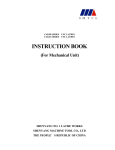
7.
By right clicking on the Explorer / Finder button, the default location for the window to
open can be set, i.e. the location of your sound effects library - this can be any drive
anywhere on the network.
Click here to
open Explorer
or Finder and
Right click here
to set default
directory path
Drag files here
from Explorer or
Finder window to
upload the file to
theTiMax HDD
8.
To store and recall presets, first from the File menu select “Create New Show Online” and
give it a name, then set the inputs, matrix, outputs and playback how you want them for
that preset and click the New button on the top tool bar. To recall, select the preset on the
Preset List and click on Go Preset at the bottom of the screen.
5
!
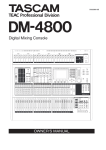
TiMax is housed in a 2 unit high 19” rack mount case. Front panel menu and jog wheel controls
allow the operator to select a show, recall presets, mute inputs and outputs and set group fader
levels.
Air intake
DO NOT BLOCK
Jog and press
to navigate
Do not
load
firmware
Activate
Bypass
signal path
(option)
Do not
load
show file
Boot from
secondary
disk
Air outlet
DO NOT BLOCK
PSU & fan
fault LEDs
In addition to soft functions
as indicated on LCD, these
buttons have special functions
during boot up, apply power and
press button to activate
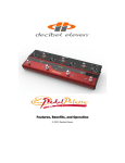
Rear panel I/O and control ports are shown for a fully loaded 64 x 64 matrix system below.
PSU B
PSU A
inlet
inlet
(standard) (option)
Bypass
Inputs
(option)
Analogue inputs
8 channels per
connector
(standard)
Analogue outputs
8 channels per
connector
C hanne l
49-64
C hanne l
33-48
C hanne l
17-32
C hanne l
1-16
MIDI 1 MIDI 2 Ethernet GPIO AES inputs AES outputs
port
port
port
port 16 channels 16 channels
(option)
(option)
Multi channel
Multi channel
audio transport audio transport
port A
port B
(option)
(option)
6
"
# $
% & #
7
' ! ()
'
&
* )
(+
*
The following is the Sub-D 25-Pin configuration. This pinout is equivalent to Tascam/Digidesign
standard analogue DB25>XLR cables.
Analogue input and output connectors on the TiMax are female and in groups of 8 balanced
circuits. D-Sub line connectors are male for both input and output.
, ! '-
%&
(+
*
!'
&
* )
. (*/
Each D-Sub carries 16 channels of input and output (8 stereo pairs) arranged in accordance with
the analogue pin-out standard. This pinout is equivalent to Tascam/Digidesign standard analogue
DB25>XLR cables
8
(* $
!(
&
Each Mixed Input Output (MIO) card has 16 channels of AES3 input and 16 channels of AES
output as well as 16 channels of analogue output.
When installing the MIO board, a jumper needs to be placed to select the word clock routing.
There can be one to four MIO boards installed in a TiMax2 unit, stacked in the IO board area. On
the uppermost board, the jumper is installed between the left two of the three posts at the JMP1
location. On all lower boards, the jumper is installed between the right two posts.
MIO inputs pass through in input Sample Rate Converter (SRC) which converts and synchronises
incoming input data to the TiMax internal clock. The SRC capture range includes 44.1KHz,
48KHz and 96KHz.
Each pair of AES outputs can be set to clock to any one of a number of clock sources including
external word clock, internal 48K or 96K or a word clock derived from any one of the inputs on
the same MIO card.
Select input
for Word Clock
synchronisation
Select synch
for each AES
output pair
Click here to
save changes
to TiMax
9
*)
0
!
!
1 2
' ! (
Multichannel I/O interfaces available for TiMax include:
Cirrus Logic Cobranet – 2 x CAT 5 transport – 32 channels on each
Digigram Ethersound – 2 x CAT 5 transport – 32 channels on each
Audinate Dante – CAT 5 transport
MADI – 2 x 75 ohm coax or optical – 32 channels on each
10
, (( '%((
&
The MADI interface is set up through the TiMax software interface, the MADI module can be set
to master or slave and 56 or 64 channel format.
Select Unit from the menu bar and choose Unit Information / Configuration, click on the MADI
tab
Click here
to set MADI
card status
Click here
to get MADI
card status
The status of the MADI card can be seen by clicking on the Update Status button. The MADI card
status report is only updated when the Update Status button is clicked.
LED Assignment:
In addition to the reported MADI status, LEDs on the MADI card will show current status:
D1 (YEL) - Rx audio data from MADI is valid
D2 (RED) - 125 MHz Rx VCO is locked (should always be on, will lock to an internal reference if
there is no valid Rx bitstream to recover a clock from)
D3 (RED) - Power good
D4 (YEL) - ~ 250 msec blink rate, based on the audio clock (power up in slave mode with no
MADI Rx, and it will be running slow since the PLL hasn't ever had a good reference to recover
from!)
D5 (RED) - MADI Rx carrier detect
11
Shows MADI card installed in unit
12
, ((
(
&
The Cobranet interface is set up through the TiMax software interface, Cobranet supports 32
channels of audio so for a 64 channel transport 2 cards are required
Select Unit from the menu bar and choose Unit Information / Configuration, click on the Cobranet
tab
Set transmit
bundles for
Cobranet
outputs
Set receive
bundles for
Cobranet
inputs
Click here to
save changes
to TiMax
13
()
* )
-2
TiMax communicates with one or more host computers on a local area network via an Ethernet
connection. The Ethernet port operates at 10 or 100 megabits per second, carrying Internet
Protocol (IP) packets that conform to the UDP protocol. A CAT5 cable is used to connect the
network port on the back of TiMax to a port on a switch, hub or router. It is also possible to
connect TiMax directly to a host computer's Ethernet port using a crossover cable (however most
Macs and modern PC computers will work with a standard Ethernet cable). Cables used
must be less than 100 meters in length. Note when using a direct cable connection it may be
necessary to turn wireless networking off on the host computer.
Each TiMax unit has a unique Ethernet MAC (hardware) address programmed into its ROM at the
time of manufacture. The TiMax firmware uses this MAC address with the ARP, DHCP and
ICMP protocols to establish and maintain connections with host computers on the local area
network using IP addresses. The IP address that the TiMax uses may be assigned dynamically by a
DHCP server on the network, or manually by the user. If there is no DHCP server present then
TiMax will auto-assign an IP address. TiMax will respond to a "ping" request on its assigned IP
address.
0
&
& , ! (3 !!
There are a number of reasons why you may consider using fixed IP addresses, it is possible that
the control computer is connected to TiMax via a Local Area Network (LAN) which is also used
for internet access or part of a wider intranet facility and for reasons of access control you wish to
limit the visibility of the system to unauthorized wired or wireless access. Using the TiMax front
panel controls scroll and press the jog wheel to select IP Address and the scroll wheel and tab key
to set the designated address for the TiMax unit, eg. 123.123.123.001
The IP address and subnet mask of the control computer will also need to be set in the same range.
For XP/Vista/Win7 this is done in Control Panel/Network Connections
Select the connection type, i.e. wired or wireless, go to the TCP/IP properties and set the address as
per the example below. The Apple Mac Network window offers similar options.
Windows TCP/IP Properties setup screen – Control Panel / Internet Connections
14
BEWARE of the following possible reasons for failure to connect:
- Windows and anti virus Firewall may prevent connection, turn firewalls off for fault diagnosis.
- If your computers’ Wired and Wireless TCP/IP settings are in the same range connection can be
prevented. Disable the one you are not using for fault diagnosis. Often necessary with Mac Airport.
- Failure to connect after changing TCP/IP settings in Windows can sometimes be cured by just
waiting for a few minutes for the new settings to become effective or by restarting the computer.
- Another device on the network has the same address as the control computer.
43(* ( )
TiMax provides a General Purpose Input / Output (GPIO) parallel contact closure interface for
triggering cues and controlling external equipment. The pinout for the GPIO connector (female
DB-25) is provided in the following chart.
All inputs and outputs are opto-isolated for reliable operation in a variety of electrical
environments. There are eight address inputs, two trigger inputs and two outputs. Each of these
inputs and outputs is a two-wire current loop, a signal line and a current return line.
pin
1
2
3
4
5
6
7
8
9
10
11
12
13
GPIO
address 0
address 1
address 2
cue trigger
address 3
address 4
address 5
address 6
playback trigger
address 7
output 1
output 2
not used
pin
14
15
16
17
18
19
20
21
22
23
24
25
GPIO
address 0 return
address 1 return
address 2 return
cue trigger return
address 3 return
address 4 return
address 5 return
address 6 return
playback trigger return
address 7 return
output 1 return
output 2 return
GP INPUTS
An input can be activated by placing a voltage on the signal line of 5 to 24 volts DC with respect to
the current return line. An input can be deactivated by placing a voltage on the signal line of 0.8
volts DC or less with respect to the current return line, or by opening the current loop. The current
loop has an impedance of approximately 4000 ohms. The trigger inputs are locked out following a
valid trigger, preventing false retriggering due to contact bounce or noise. The default lockout time
is 1 second.
There are two forms of playback GO. A simple GO, sometimes called a null GO, starts playback
on all channels that have audio files already loaded on them. It is very fast <1mS. (If a channel is
already playing audio, that channel is unaffected.)
15
A full GO specifies an audio file and a location to start playback in the file. It can take up to about
20 milliseconds from when the command is received to when playback starts.
The playback GPI trigger does two things: it recalls a preset (numbered 256..511) and at the same
time it does a null playback GO.
The other GPI trigger, the cue trigger, just recalls a preset (numbered 0..255).
When the cue trigger input is activated, the number binary-encoded on the address lines (0..255) is
read, and the cue with that number is activated.
When the playback trigger input is activated the cue at 256 + the number binary-encoded on the
address lines (0..255) and a playback GO is generated on all enabled playback channels which will
start playback within 1 millisecond for pre-loaded.
A show control GO which activates the next cue is also available by setting all zeros on the
address lines and activating a cue trigger.
43(* * )
To be implemented in future software release.
(%(
TiMax has two standard MIDI ports on the rear panel. Port 1 is a general-purpose port. Any MIDIformatted TiMax command, including standard MIDI continuous-controller commands for control
of Group Faders from generic MIDI faders as well as MIDI Show Control and MIDI system
exclusive commands can be received on the MIDI 1 IN.
In the TiMax2 SoundHub-R version, the Playlist’s Preset/Cue numbers are hard-programmed to
trigger from equivalent MIDI Program change numbers sent to MIDI IN1 on MIDI Channel 1.
The second MIDI port is for interfacing to the TiMax Tracker radar-technology performer tracking
system or to a console for remote preset recall.
The tracking system interface sends MIDI controller messages to TiMax to automatically recall
TiMax level/delay Routings when the appropriate MIDI controller signals are sent from a TiMax
Tracker computer (see later and Appendix2)
The remote preset recall mechanism uses MIDI program changes to recall TiMax presets; program
change 1-128 on channel 1 will recall the first 128 presets, program change 1-128 on channel 2
will recall the next 128 presets etc.
16
5
4
3
)5 !
These are live controls accessible via the front panel of the unit. Press the Menu button, scroll to
Groups and press the jog wheel to select. To select a Group to control, scroll to the desired channel
and press the jog wheel to select, then scroll to alter the level.
The channels controlled by a Group fader are assigned in the PC or Mac control software and may
be freely defined in each show to control any combination of inputs and outputs. So for example
Group 1 could be setup as a grand master controlling all outputs, while others may be assigned to
control sub zones, announcer mics, DJ, Band or stage sources.
Group assignments and levels will be remembered if TiMax is switched off and on again.
Group fader levels may be controlled by physical MIDI faders plugged into the rear panel MIDI 1
input port. After booting up, the unit will respond to an incoming continuous controller message,
as sent by a MIDI fader arriving on any enabled MIDI channel, setting the level for the group that
corresponds to the controller number in the message (controller zero mapped to the first group).
The default is all channels enabled. There is a command in the firmware to enable a specific MIDI
channel; message from other channels are ignored.
2
Signal levels on each input and output can be seen on the front panel LCD, the 16 channel wide
display may be scrolled with the jog wheel and input or output selected by pressing the jog wheel
switch in order to access the Mute and Solo functions .
Note: To mute and un-mute all channels, press and hold the Mute switch.
2
Use the jog wheel scroll and press to go to and select a show from the list
3
Use the jog wheel scroll to a preset from the list. Use the Select button to select that preset and
again to recall the next preset in the list.
(3 '!!
Allows setting of fixed or DHCP assigned IP addresses. (See P8.- Ethernet)
)
(
#
Displays unit information and provides facility to reset the unit to factory default.
17
4
6
5
In the event of a system crash due to firmware corruption of show file corruption, here are a couple
of things to try…
1.
Reboot the unit while holding down the left button under the LCD display – this will boot
the unit from ROM and will allow the firmware to be re-installed from the PC or Mac.
When the software is launched you will be prompted to load the version of firmware that is
embedded into the control software.
2.
Reboot the unit while holding down the centre button under the LCD display – this will
boot the unit without auto loading the most recent show file. To reinstate the show file
select File/Open Show Online, this will upload the show file from the PC or Mac disk to
the TiMax unit.
3.
Reboot the unit while holding down the right button under the LCD display – this will boot
the unit from the secondary disk (if fitted).
18
&2
%
" *)
!
!%
% 7
An optional 2nd hard disk drive can be fitted into TiMax that mirrors the first disk and in the event
of a hard disk failure takes over.
%
3
)) "
!
&
An optional 2nd power supply and cooling fan can be fitted into TiMax for high reliability
applications. The 2nd power supply has its own power cord and fuse.
$")
An optional analogue Bypass feature can be fitted to TiMax that allows an additional set of 8
analogue inputs to be selectively routed to pre-programmed outputs outside the DSP signal path
allowing for mission critical applications to have a fail safe facility. The Bypass system does
however use analogue buffers so will not pass audio in the event of total power failure.
19
*7 7
Versions of the software are available for Mac and PC. Connection to the TiMax may be direct
using a Cat5 cable (some computers may need a cross-over cable) or connected through a switch
or hub using existing network infrastructure or wireless using a wireless access point.
The software is a live control surface for one or more TiMax DSP audio matrix units offering
control of up to 64 channels on each TiMax unit of input EQ, output EQ, level and delay at each
matrix crosspoint as well as sound file playback and sophisticated snapshot and cross-fade
automation.
Pages for Files, Presets, Routing and EQ Libraries may be hidden or visible and can be docked
either to the left or right of the fader section, or be placed where ever is most useful and
convenient.
Un-docking is achieved by clicking on the
button and docking by clicking and dragging the
page to the left or right of the screen and releasing.
For example a computer with multiple screens could have all the pages open and visible. The
Preset control page is defined as an “always on top” window.
In the example layout below the EQ and Routing library pages are to the right of the faders
section, the EQ library page can be brought to the front by clicking on its the tab at the bottom of
the screen.
20
3
!3
As supplied the TiMax unit and TiMax software do not have password protection enabled.
To set a password to allow the software to log on to TiMax or to allow user access to the front
panel controls, select the “Set Unit Password” from the “Unit” menu and set a password of
between 4 and 8 numbers with value of 1, 2 or 3. i.e. 123123. Please note that you will be
prompted to enter a new password twice.
To clear all passwords, select the “Set Unit Password” from the “Unit” menu and put a check in
the box as shown
Please note that if you loose or forget your password, there is a master password that will
allow access to any TiMax anywhere on the planet ….. it is the least memorable number
imaginable and so, being instantly forgettable it is written here in invisible ink:
[3,1,2,1,1,2,3,3]
21
4
&
!
Click this button to access detailed on-screen help. The cursor changes
when positioned over a screen item that has detailed help available. Click
the item and a detailed help window is displayed until the next click or key
press.
The software is Online when it is connected to a TiMax. This is indicated by the blinking status
indicator on the Scan button.
Several computers can connect to a TiMax, but only one can be primary. Only the primary
computer can modify the show in the TiMax. The first computer to connect to the TiMax is
designated the primary and computers that connect subsequently are designated secondary. Any
connected computer can be made primary (and all others secondary) by using the "Make This
Computer Primary" command under the “Unit” menu.
When the software is online any changes made to the show are automatically written to the TiMax
disk as well as saved to the computer's disk. A secondary computer can view the show but cannot
modify presets. A secondary control computer can modify levels and EQ but changes can only be
saved by the Primary computer
A blinking Indicates Connection; Click to Scan Network for TiMax units and go online
The drop down list shows all the TiMax units on the Local Area Network. Switch to a different
unit by selecting the unit in the list. Refresh the list by clicking the "Scan" button. If the unit has
been named, the name appears in the list rather than the serial number.
Mute all inputs and outputs, a bright red indicator on the Mute All button and bright red indicators
on the channel Mute buttons indicates muted status
Solo works like a solo-in-place system, i.e. when a channel is soloed then all others are muted.
Solo status is additive. Clear Solos will restore all soloed channels to their normal status.
Window show / hide buttons to control which windows are visible
22
Other toolbar control sets include playback transport controls,
Playback transport control buttons for global control of all playback within the current preset
And enable buttons for external control by TiMax Tracker and any Cue/Preset triggers, plus a
global audio playback enable.
Enable / Disable buttons for TiMax Tracker interface, Internal Hard Disk playback and for
automatic or external triggers e.g. MIDI program changes or Time of Day triggers
5
#
& #
When the program is launched, it loads the show that is currently open in the TiMax unit. There
may be, and probably is, a copy of this show file on your computer, perhaps several versions of
this show file. When you first save the show file, you are prompted for where on your computer’s
disk to save the file. Subsequent saves are to that location. If you open a show file, subsequent
saves are to that file. The save location can always be changed by doing a “Save As” command.
23
87
The mixer console is arranged with input channel strips at the top, output channel strips at the
bottom, and in between, a collapsible matrix display showing a variable number of crosspoint
rows. Crosspoint faders can be displayed above the matrix display. Clicking on an input channel
strip selects that channel and highlights the corresponding crosspoint row.
()
!
)
The following control buttons are common to both inputs and outputs
Links channels for ganged control – use shift click or ctrl click to select ranges of channels. Setting
EQ, gain, solo or mute on a linked channel also sets all of the channels to which it is linked. Links
are set by clicking on the link button in the first channel (which clears all other links), then controlclicking the link button on channels to be added, or shift clicking to add a contiguous range of
channels.
Inputs and output links are separate
Shows Group assignment, G is displayed if unassigned or shows group number if part of a Group
and the first Group number and + symbol (i.e. 1+) if a member of more than one Group.
See Group Master section for assignment instructions
A Group may control any combination of input or output channels, or both.
Solo, Soloing an input or output channel mutes all other input or output channels that are not also
soloed. Input Solo’s will not mute outputs and output Solo’s will not mute inputs.
If any channel is Solo is pressed, the toolbar Clr Solo button will flash, clicking on it will clear all
solos
Mute. Muting an input or output channel does just that !
Channel mute status is independent of automation control
24
,
Click on the Source Mix tab to the left of the input fader section to display input sub mixer, use the
upper horizontal scroll bar to view hidden channels.
Shows input attenuation of discrete input I/O card, Networked I/O module such as Cobranet,
Ethersound, MADI, Dante etc. (if fitted) and playback input from internal hard drive.
This sub-mixer allows selection or mixing of all three signal sources for each input channel.
Link – provides means for ganged control of multiple channels. Use ctrl click or shift click to
select a range(s).
25
()
2
Click on the Input Gain tab to display input faders, use the upper horizontal scroll bar to view
hidden channels
EQ Thumbnail – double click to launch EQ control window
Channel Label. Double-click to edit the label text. The channel labels are
stored in the Show file.
Audio is loaded onto a playback channel by dragging it from the TiMax
disk Audio list in the 'Files' window and dropping it onto this area on the
desired input channel. Stereo and multi-channel sound files automatically
are automatically ganged
Bargraph metering shows PPM response, -2dB clip indicator, -18dB
nominal operating level. Equivalent to +4dBu analogue input level.
The Channel Gain in dB is displayed under the fader. The field is blank
when the channel is off (-oo dB). Double-click to enter a level value from
the keyboard.
The Group offset in dB is displayed under the bargraph meter. The Group
offset is the amount by which the level of the channel is affected by all
groups to which it is assigned.
Link and Group controls
Solo and Mute controls.
This field contains the Routing Assignment for the input channel. A new
Routing can be created by setting the crosspoint gain and delay values on
the crosspoint row for this channel, then right clicking on this area and
selecting "New". Routing Assignments are stored in the current show file
and displayed in the Routing Library. A Routing Assignment can be
applied to an input channel by right-clicking on this area and selecting it
from the popup menu, or by dragging it from the Routing Library. An
Routing Assignment from one input channel can be dragged and dropped
onto another input channel
26
()
-9
Double-click on the input EQ thumbnail to open the control window
Each input has a 4 band parametric equaliser, the filter type of each band can be chosen from a
drop down menu and parameters can be entered by dragging nodes to alter Gain or Frequency and
shift + drag to change Bandwidth. Parameters can also be entered and edited numerically.
EQ changes made on an input that is Linked to others are automatically applied to the others
Overall and individual Flat and Bypass controls are provided.
Input EQ control screen is opened by double clicking the Input EQ thumbnail on channel strip
EQ settings can be copied from one channel to another or to the EQ Library by dragging and
dropping the thumbnail image from the source onto the destination.
To view other channels there is no need to close the EQ window, either click on the channel to be
viewed or enter the channel number in the box or us the up down spinners.
Any EQ filters adjusted in previously linked or un-linked channels will not be affected if the
linking is subsequently changed. This allows EQ offsets to be applied between linked channels.
27
,
At the heart of TiMax is a Level/Delay matrix which allows the sound reinforcement system to
support multiple simultaneous time-alignments.
Matrix settings (or Image Definitions) can be named and saved to the Routing Library so
localisations that are frequently used can be easily pasted onto input channels.
Level/delay Routings (localisation Image Definitions) may be created by a process of
measurement and calculation and imported into TiMax in CSV format. See Appendix 1 for further
details.
Matrix crosspoint level and delay values can be entered via an Excel-style matrix grid or by using
a row of matrix level/delay faders. Input numbers are show down the left hand-side of the matrix
The matrix faders are placed between the input mixer and the crosspoint matrix display. The
crosspoint faders always act on the uppermost highlighted matrix row. Clicking the button again
hides the crosspoint faders.
This button displays or hides the matrix level and delay faders
This handle drags the matrix window open to expose more rows, up to a max of sixteen rows
The number of matrix rows visible (up to a maximum of sixteen rows) can be altered by dragging
the window open or closed by clicking on the drag handle situated just below the matrix row input
numbers on the left-hand side. The mouse scroll-wheel allows you to see other rows.
The matrix level and delay faders route the selected input to the output directly below the matrix
fader.
Values may be set numerically in the number box below the fader.
To select an input, click on an input or to the left of a matrix row. The selected input and the
corresponding matrix row will highlight to indicate it is selected
To view hidden outputs use the lower horizontal scroll bar
A range of matrix input/output cells can be selected using shift click and ctrl click and adjusted in
one operation.
28
* )
2
EQ Thumbnail – double click to launch EQ control window
Channel Label. Double click to edit the label text. The channel labels
are stored in the Show file.
Bargraph metering, PPM response, -2dB clip indicator, -18dB nominal
operating level, equivalent to +4dBu analogue output level.
The Channel Gain in dB is displayed under the fader. The field is blank
when the channel is off (-oo dB). Double-click to enter a gain value
from the keyboard.
The Group Offset in dB is displayed under the bargraph meter. The
Group Offset is the amount by which the gain of the channel is affected
by all groups to which it is assigned.
Link and Group controls
Solo and Mute controls
29
* )
-9
Double click on the input EQ thumbnail to open the control window
Each output has a 8 band Equaliser, the filter type of each band can be chosen from a drop down
menu and parameters can be entered by dragging nodes to alter Gain or Frequency and shift + drag
to change Bandwidth. Parameters can also be entered and edited numerically.
EQ changes made on an output that is linked to others are automatically applied to the others
Any EQ filters adjusted in previously linked or un-linked channels will not be affected if the
linking is subsequently changed. This allows EQ offsets to be applied between linked channels.
Overall and individual Flat and Bypass controls are provided.
Output EQ control screen is opened by double clicking the Output EQ thumbnail on channel strip
30
4
)
Group master faders are used to boost and cut the gain of all input and output channels assigned to
the group. Groups contain any set of input or output channels or both. Group Solos and Mutes are
also available. Up to 32 groups can be assigned.
This button displays the Group window. Group Sliders are used to boost and cut the gain of all
input and output channels assigned to the group. If the Group Sliders window is visible, this
command will hide the Group Sliders window
Group levels may be controlled through the PC or Mac software interface, or by using MIDI
faders attached to MIDI port 1, or from the front panel of the TiMax unit.
This button separates the group faders into a separate window or re-docks the window onto the main screen.
A set of channels is assigned to a Group by double-clicking the Group buttons on the desired input
and/or output channels in the mixer window (the buttons flash on and off), then double-clicking
the Group button of the desired Group master. Shift-double-click can be used to select a range of
inputs or outputs. Group assignments can be modified by double-clicking the Group button for the
Group (all Group buttons flash on and off), double-clicking the Group buttons for the channels to
be added or removed, then double-clicking the Group button for the Group
The group button for assigned groups is light green. Clicking on an assigned group button
highlights it (bright green) as well as the group buttons in all input and output channels in that
group in the mixer window
A channel may be assigned to more than one Group. To see what groups a channel is assigned to,
click the Group button on the channel.
Groups are named by double-clicking in the label field near the top of the group fader, and typing
a name
Group channel assignments and names are stored in the Show file
31
3 & ## !
5
The File List displays the show and audio files loaded on the disk of the connected TiMax unit and
a browser of the local computer's disk.
This button displays or hides the Files window.
The File List can be docked on the right or left side of the main window, or made into a separate
window and expanded as shown below.
The Files window is a listing of all Show and Audio files on the TiMax disk
Click here to
open Explorer
or Finder and
Right click here
to set default
directory path
Drag files here
from Explorer or
Finder window to
upload the file to
theTiMax HDD
32
2
!
Show files may be created and edited on-line, i.e. via a computer connected to a TiMax unit, or
off-line, i.e. on a computer not connected to a TiMax unit. Show files may be saved to and recalled
from the computer disk, to/from the TiMax disk or both.
0
2
*
This creates a new, empty Show on the computer and on the TiMax. This command is available
only when this computer is online and primary. The Show previously open in the TiMax is closed.
The previous contents of the Preset List, if any, are deleted. You will be prompted for a file name
and disk location for the Show file. Note: The Show file is saved to the TiMax automatically
whenever any change is made, and stored to the control computer on operator command.
0
2
*
This creates a new Show for offline programming and editing. An empty Show file is created on
the computer and not on the TiMax. If the program is online to a TiMax, this command switches it
to offline mode. (To switch back to online mode, click the "Scan" button.) The previous contents
of the Preset List, if any, are deleted. You will be prompted for a file name and disk location for
the Show file. Note: The Show file will be saved to the computer automatically whenever any
change is made.
*)
! 2
,%
This opens a Show file located on the TiMax disk. This command is available only when this
computer is online (i.e. a TiMax is connected), is primary, and a Show file is selected in the TiMax
File List. When this command is executed, the Show previously open in the TiMax is closed and
the selected Show opened. When open on the TiMax, a Show is ready for Preset recall. This
command also transfers the Show from the TiMax to the computer and loads it into the Preset List.
You will be prompted for a file name and disk location for the Show file changes to be saved on
your computer.
*)
2
*
This opens a Show file located on your computer's disk. The Show is also transferred to the TiMax
disk and opened for Preset recall in the TiMax. The Presets contained in the Show file are
displayed in the Preset List. This command is available only when this computer is online (i.e. a
TiMax is connected), and is primary. Note that the Show file will automatically be saved to the
computer and to the TiMax whenever any change is made. To open a Show file stored on the
TiMax disk, see the "Open Selected Show on TiMax Disk" command.
*)
2
*
This opens a file for offline editing. The file on your computer's disk is opened on your computer
and not on the TiMax. If the program is online, this command switches it to offline mode. (To
switch back to online mode, click the "Scan" button.) The Presets contained in the Show file are
displayed in the Preset List. The name and last-modified date-time of the Show file are displayed
at the top of the Preset List. Note that the Show file will be saved to the computer automatically
whenever any change is made.
7
2
This saves the current Show to the computer's disk. If online, the Show is automatically saved to
the TiMax disk. When a Show is saved to the TiMax, the Show is also opened, i.e. ready for Preset
recall
33
7
2
'
This saves the current Show to a new name on the TiMax and computer disk via usual path
selection.
-
8
"
The EQ Library facilitates the storage and retrieval of input and output channel equalization
settings ("EQ’s”) using a simple drag-and-drop interface. The EQ Library is stored in the current
Show file whenever the file is saved.
This button displays or hides the Equalisation Library.
An EQ is added to the Library by dragging from a channel strip thumbnail and dropping it at the
desired library location.
An EQ can be applied to an input channel by dragging it from this EQ Library onto any channel’s
EQ thumbnail.
An EQ in the library can be replaced by ctrl-dragging (cmd-dragging on a Mac) a new or updated
filter from a channel strip and dropping it onto the EQ in the library to be replaced.
EQ’s in the library can be re-arranged by dragging and dropping within the library.
EQ’s can be labeled by double-clicking on the field beside the EQ thumbnail and typing a name.
EQ’s can be deleted from the library by selecting one or more EQ’s and performing a cut
command. (ctrl-X on Windows, cmd-X on Mac) . The EQ Library is stored in the current Show
file.
EQ’s from another Show file can be imported to this Library using the "Import from Show File"
command in the "File" menu. This command imports EQ’s from the specified Show file, and adds
them to the current EQ Library if the EQ is not already in the library.
34
&8
"
Matrix settings can be named and saved to the Routing Library so localizations that are frequently
used can be easily pasted onto input channels.
This button displays or hides the Routing Library.
Routings can be created by setting the crosspoint gain and delay values on a crosspoint row, then
right-clicking on the Routing field at the bottom of the corresponding input channel and selecting
"New". A name can be added in the confirmation dialogue box.
Routings can be updated by altering the crosspoint gain and delay values on a crosspoint row, then
right clicking on the Routing field in the corresponding input channel and selecting "Update".
A Routing can be applied to an input channel by dragging it from this Routing Library. The
Routing Library is stored in the current Show file.
The Routing Library can be docked on the right or left side of the main window, or made into a
separate window.
35
3
!
The Preset List displays the presets contained in a Show file. The Preset List can be docked on the
right or left side of the main window, or made into a separate window.
This button displays or hides the Preset List.
The most-recently recalled (“current”) preset is highlighted blue. Presets are kept in preset number
order. Preset numbers can be changed (using preset Update) to rearrange the preset order. A preset
can be inserted between two existing presets by using decimal points. For example, preset 10.5
will be inserted between preset 10 and 11. The number after the decimal point can be between 0
and 255. Up to two decimal points can be used, for example, 10.200.120. When the program starts,
if a TiMax is found on the network, the Show open in the TiMax is automatically loaded into the
Preset List. If no TiMax is found, the program goes into offline mode and the Show file last
opened on the computer is loaded into the Preset List. The name and last-modified date-time of the
Show file are displayed at the top of the Preset List. If the computer is online and primary, the
Show in the TiMax can be changed using the pop-up list. The Preset List can be docked on the
right or left side of the main window, or made into a separate window.
3
The ‘Go’ command recalls the selected preset and advances the selection to the next preset in the
list. The current preset is indicated by a dark blue background. Preset recall can also be triggered
using the space bar, hot key or by MIDI program change. The up and down arrows can be used to
scroll though the preset list.
0
3
The 'New' preset command creates a new preset by capturing current settings (such as gain and
delay values). When the preset is recalled, captured gain and delay settings are crossfaded over the
time period specified
)!
3
Use the Update button to update the current (dark blue) preset in the Preset List to make any
changes to channel parameters, playback commands, numbering, notes or triggers. When you hit
Update the Preset dialog is opens, offering same parameter options it had when the Preset was first
stored or last modified. Simply click Update without changing these parameter options to update
the preset with the modified mixer settings, keeping the stored parameter categories and channels
the same. Changing the channel or parameter options in the dialog before pressing 'Update' allows
36
channels or parameter categories to be included or excluded from this preset update. To include or
exclude specific channels from the Preset update, these must be selected or de-selected before you
hit the Update button.
"
# 3
The ‘System’ preset is a special system configuration preset that contains Output Level, Output
Delay and Output EQ data. The System preset can be updated at any time by clicking on the
System button, so if any changes are made to any of these parameters during the run of a Show,
they can be saved independent of the main preset list. The system preset is automatically
recalled whenever a Show is loaded.
The System preset can be thought of as analogous to a conventional sound system loudspeaker
controller or drive-rack settings.
The System preset’s settings can subsequently be overridden live during the Show by normal
presets if they include changes to outputs.
The check boxes for options: Recall Routing Gain Ramps Enabled and Recall Routing Delay
Ramps Enabled allow tracking system control to morph levels and or delays from stage zone to
zone, the Recall Routing Ramp Time box allows a user defined ramp time to be set.
37
3
)!
%
&
The New Preset dialog shows a number of text and check-box options to edit or specify when
storing the Preset. The Preset can be given a number and a name and a Note can be added. You
can choose to store selected (ones that are highlighted before you hit New or Update) channels in
the Preset or you can choose to include or exclude all input and output channels in the Preset.
Types of channel parameters to be included or excluded in the Preset can be selected from Input
Gain, Crosspoint Delay, EQ, Source Mix and Output Gain and Output Delay. You can select
audio Play commands to be initiated when you recall the Preset. The Select Audio Operations
window will display all audio files which are currently loaded onto channels and allow you to
select one or more to Play when this Preset is activated.
3 & ##
&5 !
!5 !
#
Presets can be programmed to fade-in and fade-out their stored parameter changes when the Preset
is recalled. You just enter the Fade Time and Fade Out Time in the boxes shown. Crossfades can
be achieved by storing consecutive presets with different pairs of channel fader in opposite up and
down positions for instance. Fade out times only apply to input or output faders that fade out to
fully off.
38
!5
3 "
##
!
To program a sound file to play in a preset, firstly upload the sound file or clip to the hard disk on
the TiMax and then use drag and drop from the TiMax files window to the input channel playback
region just below the input channel label and above the fader to load the clip to a particular
channel. Note that if the sound file is stereo it will link a pair of input channels and playback as a
stereo file.
From the Preset window select New or Update to bring up the Preset store dialogue.
When programming audio playback there are 4 command options offered for each audio clip
loaded onto a channel.
Play from the beginning of the clip
Play from the point at which the clip is paused
Pause Clip on preset recall
Unload Clip after fadeout
39
3 & ##
&
#
% "
&&
Presets may be triggered from user defined Hot Keys or from a specific Time of Day or a
particular date defined the Triggers command screen. To use Time of Day triggers it is necessary
that the system clock is set.
Note that the system clock has no knowledge of daylight saving changes to local time.
The example above will trigger this cue at 10 seconds past 9am every day of the week.
&
#
Under the “Unit” menu, select the Set Unit Clock option. The unit clock is set to the same value as
the computer connected to it.
(%( &&
In the TiMax2 SoundHub-R version, the Playlist’s Preset/Cue numbers are hard-programmed to
trigger from equivalent MIDI Program change numbers sent to MIDI IN1.
40
&
)
Several computers running the TiMax controller software can be networked together to offer
distributed control of a single or multiple TiMax matrixes.
For example a controller could be sited at the FOH position, a second at the stage manager position
while a third could be wireless connected and roaming allowing several operators to have access to
separate parts of the sound system.
The first computer to go on-line to the TiMax matrix is designated the Primary controller as
indicated just below the unit name box. This is the only controller with rights to save presets or
changes.
Any controller can be made Primary by selecting the ‘Make this Computer Primary’ option under
the ‘Unit’ menu.
41
2 &
!
2 & &
&
Shift-Ctrl-Alt-R will restart the software in the TiMax Unit
A set of Backup show files always are stored in Documents & Settings / User / Application Data / TiMax
II/<yourfilename.tm2> in addition to saving the show files in your working data directory so if this directory is
lost or deleted accidentally then the show file can be retrieved from this location.
Or
From TiMax 2 software Open TiMax Files Directory
A User Interface Log file is saved in the TiMax Files Directory which may help solve mysterious issues.
The UI Log file has a date coded name like TiMax2_2011_09_05_20_36_41.log
A Unit activity log is saved on the TiMax disk drive, in the case of a hardware crash it could be of great help
to our ongoing product development program to have this file – to get the file, go to the Unit menu and select
the item Write Unit Log and Restart Unit. Then from the Files Menu select the item Get Unit Log File which
will upload the unit log file to the TiMax Files Directory.
The Unit Activity Log has a name like T2CBD022.log – i.e. it is the coded with the TiMax ROM serial
number and is usually quite large i.e 20Mb but will zip to a file size of around 500 – 600Kb
Zip the Unit Log File, the UI Log File and the Show file and send them to us.
42
:
(
!
The S version software and associated firmware provide additional sophistication and functionality
to the playback and show control capabilities of the TiMax system.
The S version software must be licensed to the TiMax hardware on which it is run.
*7 7
The S Version software includes additional control interfaces for a Timeline Editor allowing direct
manipulation of sound file playback, dynamic volume profiles, dynamic panning using library
Routings (Image Definitions), non destructive editing of audio files in Cues and a Pan Space
Editor allowing freehand programming of spatial control of sound.
5
& #
When you launch the program, it automatically retrieves the copy of the program currently
running on the TiMax unit. If you are the show programmer, you have to explicitly manage your
show file. If you are sure that the copy of the program currently running on the TiMax unit is upto-date with your copy on your computer, then you can do a Save-As and overwrite your local
copy. If you are sure that your copy in your folder on your computer is the master, latest copy then
the safest thing is to explicitly open your copy from your folder when you start your editing
session. Once you open your copy, the program knows that that is the copy to write when
you save.
Under the Show name in the Preset List Panel, the most recent modification date / time of the
Show is displayed. After changing anything in the Timeline Editor, this date / time is updated, to
indicate the changes have been saved to that Cue and Show. Shows can also be Saved manually at
any time to create back-ups. Edits made with either Snapshot or Timeline editor can be cancelled
and restored (up to ten edits) using Undo and Redo.
#
8
-!
The Timeline Editor can put commands (i.e. volume profiles, start playback, recall Image
Definition, MIDI and clock commnads.) anywhere on a Cue’s internal timeline.
The timeline editor is a graphical editor that lays out the cues in the show and the elements within
each cue on a timeline for easy and accurate manipulation of all of the timings of all of the
elements. It is presented like audio workstation software, waveforms are displayed together with
the audio tracks and gain contour lines, etc. It is optimized for cue recall in live sound
performances.
The timeline editor provides an intuitive user interface for complex, accurate and editable sound
localization. The system is quarter-frame accurate in time, more or less tenth-dB accurate in gain
(varies over the range) and millisecond accurate in delay.
43
Localisation is achieved by setting up a number of image definitions in a performance space.
These are then used to locate and move sounds as required by the show's design goals. The system
interpolates gain and delay in real time between image definitions on the timeline.
All Cue edits made in the Timeline Editor are automatically saved; no user action is required to save the
Cue or Show to PC/Mac disk and into the TiMax unit.
) 2
!
#
1-,
A mixer surface snapshot can be included at the start of a TimeLine cue if an opening setup is required. I
cue can consist of just a snapshot or just a timeline event sequence or both. In the case of both, the snapshot
is executed and then the TimeLine events follow.
A Shaphot can only be edited using the snapshot editor and a TimeLine cue can only be edited using the
TimeLine editor.
The major significant difference between an R Version and S Version snapshot is that an S version snapshot
cannot contain an audio clip play command, this must be programmed as a TimeLine event – i.e. the audio
must be dragged onto the channel in the TimeLine window.
44
The screenshot above shows snapshot elements including an input fade, input EQ change and a matrix setup
in cue 5 saved to channel 6 with the snapshot fade time indicated by the shaded area of the screen.
8
! &' ! 5
Audio files can be dragged from the TiMax2 SoundHub Files Panel or from any accessible disk
drive on the network and dropped anywhere onto a Cue timeline. Audio files already loaded onto
the TiMax disk appear in the edit window section at the bottom of the screen if nothing is selected
(as shown above).
An audio region appears with the audio waveform inside. If there is already an audio clip in the
Cue, the new audio clip can be added to the end of the previous clip on the same track to play after
the first clip or to a different track to play concurrently with the first clip. This way you can build a
multi-track montage by dropping audio files onto a Cue in the order they should be played. A
short gap is placed between audio files. Audio regions can be moved by simply dragging them
within the Cue. They can be slipped forward and back in time and they can also be dragged up
and down between channels. Track slip needs is Enabled via a checkbox in the Cue edit dialogue
that comes up when you click on the clip.
Whenever an audio file is dropped anywhere over top of another one already on the timeline with
the same starting channel, the dropped file will automatically be placed so that it starts exactly
where the first one ends. In other words, the timeline automatically moves audio files so that they
do not overlap.
When you drag a sound file into the file window (or onto a track on the timeline), the file is
converted to the format required for the TiMax. This file is sent to the TiMax and a copy is kept in
the local TiMax directory. This directory is located in different places on different operating
systems, but can always be found by selecting "Open TiMax Files Directory" in the Files menu.
On a Mac computer, for example, the file is kept at username/Library/Application
Support/TiMax2 (username is the name you have for your home directory).
Keeping a local copy in the TiMax format of the audio file speeds up a number of subsequent
operations, including, for example, making a show archive. If audio needs to be re-loaded and
there is no archive file, using the copy in the TiMax directory means the file can be transferred
quite quickly, without needing to re-convert it.
As with all playback engines, after a start playback command there is short time required to
preload audio buffers in RAM before playback can start. This is on the order of 10 milliseconds
per channel, and so is usually not an issue. However, if you are starting up a batch of files at the
same time and they need to be perfectly synchronized, they need to be pre-loaded. If all the
channels are built into a single multi-channel sound file, the channels will always be perfectly
synchronized.
To pre-load audio, a pre-load audio icon needs to be placed on the starting channel for the audio
files in the immediately preceding cue.
Clicking on an audio clip or an event marker within the clip displays an edit dialogue through
which the Playback Start, or Play Zone start and stop, loop points and volume nodes can be
viewed and edited. Additionally looping can be enabled.
45
# 8
On the left hand side of the TimeLine window are a number of icons that can be dragged onto the
TimeLine to program automation and show control events.
Drag to channel to set a volune node
Drag to channel to set an Image Definition or Pan Point
Drag to channel to set an Image Definition or Pan Point
Drag to channel to stop an continuous loop
Drag to channel to pre-load audio in next cue
Drag to event bar to program a Go Cue command for auto follow sequence
Drag to event bar to program a stop cue event
Drag to event bar to program Start Show Clock for programming event sequences
Drag to event bar to program Stop Show Clock
Drag to event bar to program Start MTC Clock
Drag to event bar to program MTC Show Clock
Drag to event bar to program MIDI Event
Select custom colours from a pallet
##
The cue time edit tools appear when any automation item is selected on the time line
Event times can be nudged up or down or set to the start of the cue, the red arrow will snap the
event to the current playhead cursor position
' ! 5
-!
&
The Start point of the audio file can be adjusted by clicking on the audio region to select it, then
clicking down in the semi-circular handle at the beginning of the audio region and dragging right
or left. Similarly, the End point can be adjusted by clicking down in the semi-circular handle at the
end of the audio region and dragging. When an audio region is moved, any gain ramps and Image
Definitions within the region are moved with the audio region. An audio region can be deleted by
selecting it and pressing the Delete key.
46
8
) &
Independent looping on individual waveform tracks can be activated by clicking on the audio clip
and checking the Enable Looping box. This opens further options including Loop Start and End
points which can be edited numerically or graphically as well as the, duration or number of loops.
Loops can be set to run a defined number of times or indefinitely until a cue with a loop end
command is triggered.
Audio looping is available with any audio file. Loop start and end points may be set, and a
crossfade is automatically generated at the time of the loop. The crossfade duration may be set to
get the desired crossfade time.
The play controls in the bottom left of the loop editor are useful for setting up and previewing
loops independently of the current playback status on other tracks. To enable these controls the
playhead must be dropped into the looped region and the looped clip must be selected.
Currently, gain and image definitions in the loop zone are not repeated automatically when the
audio loop occurs. If this is required, leave looping off, trim the audio to the loop zone, put the gain
and routing elements in that you want, then shift click to select the audio and the gain and image
definitions that are within the audio zone, copy it and then paste it as many times as needed. A
later version of the software will have the capability of repeating the gain and image definitions in
the loop zone along with the audio.
47
#
3
&
Volume profile Gain nodes can be added by double-clicking on the volume contour line or by
dragging a node from the tool bar to a clip, to adjust the Node click on it and drag up or down or
side to side. Multiple nodes can be linked and adjusted using ctr-click(PC) or cmd-click(Mac) and
dragging one with ctlr or cmd still held down at the start of the drag. Alternatively a group of
nodes can be selected by dragging a box around them.
The gain contour lines illustrated in the timeline are exactly followed when cues are run, except
between the start of a cue and the first gain point on a channel in the cue. This is because when a
cue is triggered, the gain level on a channel is programmed to go from where it currently is to the
level contained in the first gain point In order to draw a gain contour line on the timeline
between the start of the cue and the first gain point on a channel in the cue, the software has to
assume a starting gain level. In practice, the actual starting level could be anything, since cues can
be triggered in any order, and even if they are run in order, previous cues are not necessarily run to
completion and can contain many gain changes. The software assumes the gain level of the
previous gain point on that channel in some previous cue (or zero if there is no previous gain
point). This means that if all cues are run to completion and run in order, the illustrated gain
contour lines between the start of a cue and the first gain point on a channel are followed. In
practice, the actual gain contour between the start of a cue up to the first gain point could in fact be
anything. Note in particular that re-running a cue is an example of cues being run out-of-order.
3
&
(# & %
A fundamental concept in the TiMax system is the "image definition" or "routing". Think of this as
a location in sound space. It is created by setting the gains and delays for the incoming sound
(incoming from outside the TiMax or from the internal playback) for every loudspeaker in use.
When set up correctly this will give better than 90% of the audience the perception of that sound
being at that location, depending of course on the dimensions of the room and the number and
locations of the loudspeakers. There are accurate methods for setting up the image definitions so
that are relatively easy to do and work well acoustically. These image definitions are stored in a
library and then placed (using a drag and drop) into a cue on the timeline. When the cue is
triggered, the gains and delays of all of the image definitions in the cue are interpolated from one
to the next, generating smooth diffusions between locations.
48
Image Definitions (or “Routings”) can be added to a Cue in the Timeline Editor by dragging from
the Routing Library and dropping onto a Cue in the Timeline. Image Definitions can be moved
within a Cue by dragging. Multiple Image Definitions can be selected and moved as a group. An
Image Definition can be deleted by selecting it and pressing the Delete key.
(See R-Version section for how to create and save Routings / Image Definitions in the Mixer screen)
%" #
3
When the Cue is triggered, the level/delay pan localisation of the first Image Definition on a track
waveform is applied to the audio. This pan position holds until the Cue cursor passes the first
Image Definition and heads toward the next Image Definition on the waveform. The level/delay
pan settings then begin to interpolate from the first to the second Image Definition as the cursor
moves towards it. This continues for other Image Definitions placed on the waveform until the
cursor passes the last Image Definition. The audio then stays panned to the last Image Definition
until the end of the Cue.
2
& &3
8
!
#
&
The timing and pan law between pairs of Image Definitions can be adjusted by dragging them
apart or nearer on the waveform. Their position can also be nudged by numerical entry in the
floating dialogue boxes which appear when you select an Image Definition.
To select an audio file and all gain points, image definitions and other elements that are within the
audio region, hold down the shift key when clicking on the audio region.
Image definitions are anchor points, or locations in the performance space.
When there is more than one image definition in a cue on the timeline, the gain and delay values
crossfade automatically between values in the image definition as the cue runs. This automatic
crossfading between image definitions is a truly powerful feature of the software.
A period of no crossfading is accomplished by repeating an image definition. The system will in
fact crossfade as usual between the two image definitions, but because the two are identical there is
no actual change to the level or delay of any of the crosspoints.
An "instantaneous" crossfade happens when two different image definitions are placed very close
together. The shortest gain and delay change is 32 milliseconds.
49
Audio files can be moved along the timeline by dragging them with the mouse or by setting the
time using the time control in the editor. If the audio file is locked ("Position Locked" checkbox is
checked), the audio cannot be moved.
To move an audio file to a different track, cut it and then paste it to the new track.
+
Image Definitions can be dragged onto either channel of a stereo waveform or both. If dragged
onto only one channel this has the effect of muting the other channel by just not routing it through
the matrix. If identical Image Defs are dragged onto both channels in the same position this has
the effect of mono-summing the stereo track.
)
3
&;
!
A subsequent S-Version release will have a spatial panning window which allows pan moves to be
programmed manually by dragging a mouse round a set of Image Definitions spread out on the
screen. Different parameter and timings can be adjusted relating to individual inputs and Image
Definitions.
2
&&
Cues are triggered in a variety of ways: manually pressing the GO button or pressing the key
shortcut equivalent, Shift-return, from show control Go Cue command, via the GPI ports, via
MIDI note, program change or controller, via MIDI Timecode or via an ethernet XML command
from an external controller, from a hot key.
Use the drop down selector to choose the trigger for each cue
!
&&
To trigger a Cue from a MIDI message, just send a MIDI Program Change on MIDI in 1 or 2 port,
the system allows full MIDI mapping to Program, Note and Controller numbers selected in the
Update Preset dialogue box Triggers tab.
TiMax runs multiple clocks which can be shown or hidden on the cue list by clicking on the clock
name button.
50
The S version software includes a stop watch useful for timing events, it is manually started and
stopped and can be displayed by clicking on the Stop Watch button at the top of the cue list.
2
The show clock is be started as an automation event by dragging the show clock start icon onto the
event bar in the timeline window, once started the show clock can be used to trigger subsequent
cues.
After a Cue is triggered, its Cue clock is running. It can be stopped and re-started by pressing the
Cue play-pause button in the upper left corner of the Timeline Editor (or the space bar).
The Playhead cursor indicates the current Cue time, which is displayed numerically below the Cue
play-pause button top-left. After setting up the next Cue by clicking on a Cue in the Preset Panel
(or using the scroll bar on the left of the Preset Panel), the Playhead is at the beginning of the Cue,
and the timeline scrolls horizontally to display the Playhead at the start of the Cue. If a Cue is
running, the timeline always displays the Playhead, automatically scrolling horizontally as
necessary. As soon as the Playhead stops, either by reaching the end of a Cue or because the Cue
was stopped manually, the automatic scrolling is disabled and the Playhead can be freely moved.
The horizontal zoom tools always centre the Playhead in the window.
*
The TiMax Midi Time Code generator can be started and subsequently stopped as a timeline event
by dragging the MTC start icon from the tool bar onto the time line. Clicking on the start icon
allows the start time to be set.
51
The MTC frame rate is set by opening the MTC clock display and right clicking on the frame rate
number box.
Cues can be triggered from MTC out by setting this as a cue trigger option in the cue create or edit
dialogue.
(
The MTC receive frame rate is auto-detected when MTC input is seen at the Midi 1 in port.
Cues can be triggered from MTC in by setting this as a cue trigger option in the cue create or edit
dialogue.
#
8
!
A Go Cue follow-on command can be assigned to trigger a subsequent Cue while a current Cue is
playing. Double-click on the grey Cue flag bar in the TimeLine window to drop a small Go Cue
flag. Single-click on the flag to open a dialogue box to enter the Cue you wish to be triggered by
this Go Cue. The timing of the Go Cue can be adjusted by dragging it along the grey timeline or
entering a number in the dialogue box.
When the main Playhead passes over the Go Cue flag The Playhead jumps to the next Cue and
starts playing it. A smaller white cursor appears on the previous Cue’s waveform(s) and carries on
playing single or multiple clips in that Cue.
Alternatively, Go Cue flags can simply be placed at the end of each Cue and programmed to
trigger a series of Cues automatically one after the other.
' !
&
While a Cue is playing, the Playhead cursor and audio playback can be instantly re-started
anywhere in the Cue by clicking on the Cue Timeline bar (just above the Cue Flags bar. The
Playhead cursor will jump to this position and audio will start automatically.
The play button in the audio editor is for auditioning purposes. It always plays from the playhead
position. It is enabled when the playhead is somewhere over top of the audio, giving it a starting
playback position. If you want to play the whole cue from an arbitrary point, you can just drop the
playhead and hit the cue clock button in the upper left (or the space bar). Occasionally you want to
hear just the audio without invoking all of the gain and crosspoint moves. That is what the play
button in the audio editor (bottom left) is for.
When you trigger a cue, you start a sequence of commands. Each command has a time associated
with it. The timeline editor sets the time for each command based on where it is on the timeline.
Each command does a different thing, perhaps for example changing a gain level or starting a
sound file playing back.
When for example a sequence of audio files is placed into a cue, the TiMax is programmed to play
these files back at the specified times (from the time the cue is triggered), and it will do this even if
another cue is triggered in the mean time. This overlapping cue behavior is essential, for example,
to build complex soundscapes.
If every cue is played to completion, there is no issue. If not, the following can happen: a cue
containing a sequence of audio files is triggered. All the audio files in the cue are scheduled in the
52
TiMax firmware to play at some future time. Suppose that somewhere in the middle of the
playback of the sequence of audio files, before the cue has completely played out, the following
cue is triggered. The show programmer might not expect anything from the first cue to happen
during the second cue, but it does. What can happen is that an audio file from the first cue can
suddenly, unexpectedly, start playing back in the middle of the second cue. Also, gain points and
routings that occur in the middle of the first cue can occur during the second cue. The TiMax is
doing what it was told. The show programmer might expect triggering a cue to cancel all
previously running cues, but it doesn't, unless you explicitly tell it to.
If the show programmer wants to stop a cue when another cue is triggered, the solution is to put in
a STOP CUE marker onto the clock bar below the timeline tracks, and tell it which cue you want
to stop. Stopping a cue cancels all the commands currently scheduled by that cue.
53
'))
!,
(# & %
) "
#
!
Instructions for TiMax Generic Image Definition Calculator Spreadsheet – Copy available on request
Preparation
Check that the system is fully working and all amplifier gain is set so each loudspeaker is giving the same level in its coverage area.
Equalise the system so each loudspeaker has similar tonality
Step 1
Select and mark sample seats for measurement, best practice is to select the closest seat on axis to each loudspeaker and mark with white
tape.
On the Distances tab in the spreasheet, enter distances in meters into row 3 of the spreadsheet. These are measured values from the marked
seat to the loudspeaker. Best practice is to use an audio analysis program such as SmaartLive which will allow measurement of the distance
using the propagation time of sound from the loudspeaker to the seat, the advantages of this method are; system latency is taken into account
(console + digital signal processor processing time), and that getting a laser measurement from the front of a loudspeaker can be difficult.
Overdelay
2
Distance from Loudspeaker to Sample seat
Id No
10
Id Name OP1
10
OP2
10
OP3
10
OP4
10
OP5
Step 2
Select stage action area centers and mark and label with white tape. Best practice is to divide the stage into zones, each zone should be
around 5 meters diameter.
Making zones too large may result in poor intelligibility while making zones too small will require a lot of measurement !
Measure the distance in meters from each stage zone centre to each marked seat and enter this data into the spreadsheet on the distances tab.
Distance from Listener to Loudspeaker
Id No
10
10
Id Name OP1
OP2
10
OP3
10
OP4
10
OP5
1
A
10
10
10
10
10
2
B
10
10
10
10
10
3
C
10
10
10
10
10
4
D
10
10
10
10
10
5
E
10
10
10
10
10
6
F
10
10
10
10
10
7
G
10
10
10
10
10
Step 3
Select the Calcs&Results tab on the spreadsheet to see the calculated results for delay in milliseconds.
From the Excel File / Save As.. menu, select save as <filename>.csv to save the file in Coma Separated Variable format so that it is suitable
for import into TiMax.
Step 4
Delete unused rows and columns of figures, i.e. for unused stage zones and loudspeakers.
Carefully review the results and zero any negative delay values that have resulted from situations where stage zones are closer to sample
seats than the loudspeaker covering that area.
Once complete save the spreadsheet again in .csv format.
Step 5
From the TiMax File menu, select Import from CSV file, navigate to the file and Open.
The calculated Image Definitions will now be available to be used by opening the Routing Library in TiMax.
Notes
1.
2.
3.
4.
5.
Use the overdelay value to effectively increase or decrease the size of the stage zone
Image Definition names may be changed but do not alter the Image Definition numbers in column A
Loudspeaker names may be altered in the Distances tab but not in the Calcs&Results tab
All loudspeaker levels are set to be 0dB – these can be altered in TiMax or the .csv file if required
Considerable savings can be made in the number of measurements required if the stage and auditorium and speaker setup are
symmetrical by “mirroring” measurements around the centerline of the stage and auditorium.
54
'))
,
!,
2
)
!
)
55
56
'))
!,
! "
4
)
)
# !
!
&
, #)
)
In all cases outlined below there are a number of common themes that are worth of brief
discussion; firstly and most importantly these techniques are focused on achieving the most natural
sounding and un-amplified results in situations where amplification is absolutely necessary due to
the scale or environment of the production.
This can really only be achieved by using a distributed loudspeaker system with loudspeakers
located and targeted at the audience such that there is minimum angle of difference between that
being amplified and the speaker amplifying it. In other words you cannot amplify an acoustic
source in front of the listener using a loudspeaker to one side or behind.
The human hearing system is binaural. This gives people the ability to hear multiple sounds via
two separate aural receptors and thus draw clearer conclusions about the positions of the sources of
the sound. Listeners make judgments about the distance of the sound source and their acoustic
environment based on their perception of echoes and reverberation and the frequency-dependent
absorption characteristics of reflective surfaces within the environment. The main clues to
localisation of sound are provided not only by differences in sound levels but also by sound
wave arrival times at the ears. These differences allow people to "focus" their hearing onto what is
of interest to them and to filter out what is not (this has been aptly named the Cocktail-Party
Effect).
Delivering sound to an auditorium from a large stereo loudspeaker system prevents the audience in
most listening positions (i.e. anywhere off-centre) from properly localising anything other than
extreme panoramic information in the sound mix. This is because the sound from the closer
loudspeaker will arrive at a listener's ear before the sound from the more distant loudspeaker. The
psychoacoustic law of Precedence, sometimes known as "Haas-effect" after its originator, dictates
that for a sound coming from two or more speakers the listener will perceive the sound as coming
from the closer loudspeaker due to its earlier arrival time, in many cases even if the more distant
sound is louder due to the effect of a pan pot. Thus an audience member's perception of stereo
imaging in a stereo sound mix will only be as good as their proximity to the centre line of the room
dictates.
The way to deal with this is to implement a Source-Oriented Reinforcement ("SOR") system,
which, as well as achieving the desired even distribution of sound level over a large listening area,
will also maintain directional information from multiple sound sources, so that the "audio position"
of a presenter, actor, musical instrument, recorded program channel or special effect sample
authentically matches the actual, "visual position" or required contextual localisation. This
outcome reduces listener stress and improves intelligibility and hence message impact for all
audience members, as well as typically widening the 'sweet spot' for creative panoramic or spatial
information in the sound mix to over 90 per cent of the audience listening positions.
The principle reason why SOR works is its exploitation of natural ways of hearing. An SOR
system utilises a special type of multi-channel audio matrix which provides the possibility for
every audio source to have it's own unique level and time
delay setting to every loudspeaker,
57
which allows every sound source to be independently and identically localised for every audience
member. Stereo music reproduction from a distributed SOR loudspeaker system is achieved by
using the delay matrix to feed several loudspeakers with both channels of the stereo signal, but
delayed and summed so as to maintain the left and right perspective of the two signals for all
listening positions.
The same idea can be used to reproduce pre-recorded film surround sound material; each of the
five signals intended for the L, C, R, Ls and Rs loudspeakers can be fed into the matrix and the
signals delay-matrixed such that a distributed system gives a better delivery of spatial information
for all audience members by creating a "virtual" surround sound environment rather than relying
on a conventional "discrete" surround configuration. SOR techniques have been used for top
international productions of musicals, plays, arena operas, concerts, dance clubs and artists, special
effects soundscapes, as well as many major corporate promotional events. Although very different
in application and outcome, typically their shared agenda is audience immersion and dramatic
impact, often with the addition of enhanced panoramic surround and animated audio effects.
Digital tools now allow us to measure and adjust how speaker drivers and loading devices interact
with each other and their enclosures, how these enclosures then interact when arrayed together,
and how this integrated system interacts with the spaces we place them in. The final link in the
chain is to consider how people interpret auditory information and to deliver sound in a
sympathetic way.
In recent years the smart money has begun to include psychoacoustics in their sound design
deliberations, in acknowledgement of the inescapable symbiosis between Speakers, Spaces
and Senses.
58
")
&
5
Because TiMax is essentially a time delay processor, there is no need to time align the loudspeaker
system in the traditional way. If 2 way or 3 way active loudspeakers are used then a loudspeaker
processor may be required for cross over functions and inter-element time alignment within the
box, however if speakers with passive crossover are used with separate subs then TiMax can
provide HP and LP filtering between mid-highs and subs and no other system processor is
required.
.
59
- !1
3
#
2
On-stage loudspeakers are targeted downwards to provide monitoring for singers as well as into
the auditorium to provide time corrected amplified first wave front support of the acoustic output
from the mouths of the singers. Auditorium speaker placements are chosen to amplify on-stage
action with speakers pointing at the audience at such an angle so as to reinforce acoustic energy
and wave-front direction from the stage from the minimum possible angle of deviation from the
acoustic source as is possible within the constraints of scenic design and sight lines.
60
'# )
*)
(
2
!
Main sound reinforcement speakers arranged as an exploded cluster arranged around the edge of
the performance space. This allows each loudspeaker to have a unique delay from each
microphone thus enabling TiMax to keep the amplified and acoustic signals in time and maintain
precedence from the singer or front-fill if the singer is off axis or far away.
Front fills are built into the stage floor or disguised in scenery or props. These speakers fulfill the
important task of keeping the sound on the floor while the singer is off axis the audience in that
area.
61
2
* !
'
TiMax used in conjunction with TiMax tracker can be used effectively in large scale outdoor
theatre to provide auditory cues to alert the audience where to look.
The audience area in this example is zoned into 8 areas and each area is provided with a left and
right loudspeaker. The front row of speakers are built into the front of the stage and aimed to shoot
over the heads of the front rows of audience. The secondary row of speakers are mounted on poles
and used to minimize drop off in level towards the back rows of seats.
Each of the principle performers’ radio microphone is amplified to the audience area with a unique
level and delay dependent on the performers position on stage thus rendering an auditory
perspective that is in keeping with the visual perspective over a stage width in this case of 50
meters.
62
"
3 &
Left and right seating stands are covered by six loudspeaker arrays mounted on poles down each
side of the arena. Each array consisting of one long throw loudspeaker covering furthest seats and
two near field loudspeakers covering seats near the front.
The end block of seats are covered by ground stacked line array systems with bottom boxes
shooting just over the heads of the front rows and top boxes aimed to reach the back rows.
The primary consideration is to keep acoustic and amplified signals in time no matter where the
source is located in the arena and from all listening positions in the arena.
63
2
!!
In this example TiMax and the TiMax Tracker were used to achieve both localization and
feedback control
While the action takes place in front of the audience the speakers are time aligned to the actor
position on stage, however when the action goes to those areas behind the audience but in direct
range of a speaker, then TiMax recognizes those zones and applies a mix-minus regime.
64
'))
= 8
!,<
##
!
Advanced Usage XML file format
The TiMax software writes Show files in XML format to the Computer disk (the file written to the
TiMax internal disk includes both the XML data and executable binary data). It is possible to edit
these XML files using an XML editor or an ordinary text editor like WordPad. Doing so opens up
many possibilities that are not available when creating and updating presets using the TiMax
software. For example, it is possible to sequence the commands in a preset, starting each command
at a different delay after the preset is recalled. It is possible to have different commands within a
preset generate ramps of different durations. It is possible to generate new presets using copy and
paste operations.
Editing the Show file in XML format requires familiarity with the command set of the TiMax unit,
as expressed in the XML format. The command set is specified in the document
"Timax2XMLFormatx.x.html", available from Out Board. This document should be read carefully
before attempting to edit a TiMax Show file.
It is not recommended to edit a file using both the TiMax software and an external XML or text
editor. There is a flag in the XML file that should be set when using an external editor which
prevents the TiMax software from writing to the file. This is explained in the above-mentioned
document.
65
0
"
#
It is highly recommended that consideration is given to wireless LAN security; you may wish to
include some or all of the following measures:
Change the System ID: Devices come with a default system ID called the SSID (Service Set
Identifier) or ESSID (Extended Service Set Identifier). It is easy for ahacker to find out what the
default identifier is for each manufacturer of wireless equipment so you need to change this to
something else. Use something unique- not your name or something easily guessed.
Disable Identifier Broadcasting: Announcing that you have a wireless connection to the world is
an invitation for hackers. You already know you have one so you don’t need to broadcast it. Check
the manual for your hardware and figure out how to disable broadcasting.
Enable Encryption: WEP (Wired Equivalent Privacy) and WPA (Wi-Fi Protected Access)
encrypt your data so that only the intended recipient is supposed to be able to read it. WEP has
many holes and is easily cracked. 128-bit keys impact performance slightly without a significant
increase in security so 40-bit (or 64-bit on some equipment) encryption is just as well. As with all
security measures there are ways around it, but by using encryption you will keep the casual
hackers out of your systems. If possible, you should use WPA encryption (most older equipment
can be upgraded to be WPA compatible). WPA fixes the security flaws in WEP but it is still
subject to DOS (denial-of-service) attacks.
Restrict Unnecessary Traffic: Many wired and wireless routers have built-in firewalls. They are
not the most technically advanced firewalls, but they help create one more line of defense. Read
the manual for your hardware and learn how to configure your router to only allow incoming or
outgoing traffic that you have approved.
Change the Default Administrator Password: This is just good practice for ALL hardware and
software. The default passwords are easily obtained and because so many people don’t bother to
take the simple step of changing them they are usually what hackers try first. Make sure you
change the default password on your wireless router / access point to something that is not easily
guessed.
66