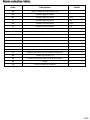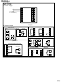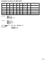
1
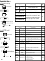
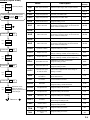
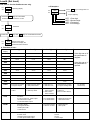
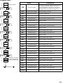
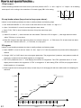
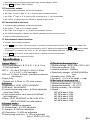
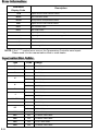
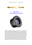
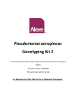
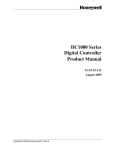
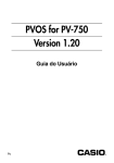
MAXTHERMO-GITTA GROUP CORP.
MC-2 SERIES
OPERATION MANUAL
Version:0607010001
CONTENT
Dimension & Cut-out ………………………………… P. 1
Panel function …………………………………………. P. 2
Operation flow …………………………………………. P. 3
How to set special function ..................................... P. 7
Specification …………………………………………… P.10
Error information ...................................................... P.11
Input selection table ………………………………….. P.11
Alarm selection table …………………………………. P.12
Hookup ………………………………………………...... P.13
Alarm action description …………………………...... P.17
Order information …………………………………....... P.18
Available function for MC-2X38.…………………..... P.19
Dimension & Cut-out:
E
D
F
B
C
A
H
G
unit:mm
P.1
Model
A
MC 2438
44.5
MC 2538
44.5
MC 2638
90.5
MC 2738
68.5
MC 2838
90.5
B
+ 0.5
-0
+ 0.5
-0
+ 0.5
-0
44.5
+ 0.5
-0
D
E
F
G
H
65
70
50
50
80
17
111
116
50
96
80
17
65
70
96
50
80
17
89
94
74
74
80
17
111
116
96
96
80
17
-0
90.5
44.5
+ 0.5
-0
+ 0.5
C
+ 0.5
-0
+ 0.5
-0
+ 0.5
68.5
90.5
-0
+ 0.5
-0
Panel function:
MC-2438/MC-2538/MC-2638/MC-2738/MC-2838
1
PV
2
SV
OUT1
16
OUT 1
OUT2
10
20
AT
30
AL1
40
AL2
50
60
AL3
70
MAN
80
PRO
90
100
8
%
~
3
SET
A/M
4
15
5
6
7
MARKS/DESCRIPTION
1
2
PV
SV
MARKS/DESCRIPTION
8
OUT 1 Output1 action indication
9
OUT 2 Output2 action indication
Process value display
10
AT
Auto tuning action indication
11
AL 1
Alarm1 action indication
Set value
3
SET Set key & enter key
12
AL 2
Alarm2 action indication
4
A/M
Manual/auto
exchange key
13
AL 3
Alarm3 action indication
5
Shift key
14
MAN
Manual action
Indication
6
Down key and program
suspending key
15
PRO
Programming action
indication
7
Up key and Program
starting key
16
OUT 1% Output percentage of out1
P.2
Operation flow:
Level1 (User level)
Name
PV
27.5
SV
27.5
Operating display
Press the SET key
PV
Out L
SV
100.0
Output
percentage
Range of setting:0~100%
Skip
AT
Auto tuning
“RUN/NO”
to be used when setting PID
NO
0
AL3/RAMP/RATE
Alarm setting range: 0-100%F.S.
But if select ramp function, it will display ”rAmP”
setting range from 00.00 to 99.99℃ /min If
select soak function, it will display “AL1” setting
range from 00.00 to 99.99 min/sec or hour/min.
If select slaver function, it will display “rAtE”
setting range from 0 to 9999. If select program
segment ending alarm function, it will display
“AL1”, setting range from 1-8 or 1-16
(AL2 and AL3 are the same as above)
Name
Description
Exfactory
AL1/RAMP/RATE
Press the SET key
At
SV
no
Exfactory
OUTL
AL2/RAMP/RATE
PV
Description
Repeat the same steps
as above to display the
parameters listed at right.
Return to “
“
Level2 (PID level)
PV
27.5
SV
27.5
Operating display
press the SET key
for 4 seconds to level 2
P1
Main Control
Proportional Band
Range of setting:0-100%
ON/OFF at P=0
I1
Main Control
Integral Time
Range of setting:0-3600 Sec
Integral off at I=0
240
D1
Main Control
Derivative Time
Range of setting:0-3600 Sec
Derivative off at D=0
60
DB1
Main Control
Dead-band
ATVL
30
Dead-band of main control
Range of setting:-10-+10
0
Main Control
Auto tuning off-set
Range of setting:0-100% F.S.
0
CYT1
Main Control
Output cycle time
When output is SSR, it is set at 3, 4-20 mA is set at 1 but output
is relay usually it is set at 20. Range of setting:0-100 Sec
20
HYS1
Main Control
Hystersis
For ON/OFF control only
Range of setting :0.0-100
0.4
Range of setting:0-100%
ON/OFF at P=0
30
PV
P1
P2
Sub Control
Proportional Band
SV
30
I2
Sub Control
Integral Time
Range of setting:0-3600 Sec
Integral off at I=0
240
D2
Sub Control
Derivative Time
Range of setting:0-3600 Sec
Derivative off at D=0
60
CYT2
Sub Control
Output cycle time
When output is SSR, it is set at 3, 4-20 mA is set at 1 but output
is relay usually it is set at 20. Range of setting:0-100 Sec
20
HYS2
Sub Control
Hystersis
For ON/OFF control only
Range of setting :0.4-100
0.4
RST1
Reset1
Adjust offset of output1 when I1 set at “0”
0
RST2
Reset2
Adjust offset of output2 when I2 set at “0”
0
AR
Anti- Integral
Setting range from 0-100 to limit integral
100
Press the SET key
PV
i1
SV
240
Repeat same steps
as above to display the
parameters listed at right.
Return to “
“
LCK
P.3
Function Lock
LCK=0000, SV, level 1 & 2 open
LCK=0001, SV, open only
LCK=0010, SV, level 1 open
LCK=0011, lock all except LCK
LCK=0100, SV, level 1 & prog. open
LCK=0101, SV,level 1,2,3 open
LCK=1010, level 4 open only
0101
Level3 (Input level)
Name
PV
27.5
SV
27.5
Operating display
Change LCK to 0101 then press
the SET key and
key for
4 seconds to level 3
PV
InP1
SV
K1
Press the SET key
PV
dP
SV
000.0
Press the SET key
PV
LSPL
SV
000.0
Press the SET key
PV
USPL
SV
400.0
Press the SET key
PV
ALd1
SV
000.0
Repeat the same
steps as above to
display the parameters
listed at right.
Return to “
“
Description
Exfactory
Inp1
Main input selections
dP
Decimal point
LSPL
Lower set point limit
Set lower point within INP1
0.0
USPL
Upper set point limit
Set highest point within INP1
400
ALd1
Alarm mode of AL1
Range of setting; oo~19
ALt1
Alarm 1 time set
ALd2
Alarm mode of AL2
ALt2
Alarm 2 time set
ALd3
Alarm mode of AL3
ALt3
Alarm 3 time set
HYSA
Hystersis of alarm
Range of setting: 0.4~100.0
0.4
CLO1
Output1 zero set
Calibrate the low value of output1
Range of setting: 0-2000( current output only )
400
CHO1
Output1 span set
Calibrate the high value of output1
Range of setting; 0-2000( current output only )
2000
OPrL
Transmitter zero set
Calibrate the low value of transmitter
Range of setting; 0-2000
400
OPrH
Transmitter span set
Calibrate the high value of transmitter
Range of setting; 0-2000
2000
rUCY
The time from open
to close of motor
Full run time of proportional motor, Range of
setting: 0~150Sec
WAit
Use in program for
SV wait PV
0=No wait
Other=Wait Volume
idNO
ID number
Communication ID number
bAUd
Baud-rate
UART baud rate selection
Range of setting:110-38.4K BIT/sec
SVOS
Compensate SV
Range of setting:-100.0~100.0
0.0
PVOS
Compensate PV
Range of setting:-100.0~100.0
0.0
Unit
Unit of PV ﹠SV
Range of setting: C,F,A (analog)
℃
SOFt
Soft filter
CASC
Cluster control
TOH
TsH
Select the input range, refer to input selection
Set the position of decimal point
It is used in program function. Range:
00~99.59mm, 0=flicker alarm, 99.59=continued
alarm, others=on delay time
Range of setting: 00~19
It is used in program function. Range:
00~99.59mm, 0=flicker alarm. 99.59=continued
alarm, others=on delay time.
Range of setting: 00~19
It is used in program function Range
00~99.59mm 0=flicker alarm 99.59=continued
alarm, others=on delay time
K1
000.0
11
99.59
11
99.59
11
99.59
5
0.0
1
2.4k
Adjust the response time of PV, the little the
faster Range of setting:0~254
200
(don’t care)
Range of setting:0~1000
0.0
The time for loop
open
Range of setting:0~120 sec.
60
The time for loop
short
Range of setting:0~120 sec.
20
P.4
Level4 (Set level)
This level is for the distributor use only
a. Example:
PV
27.5
SV
27.5
Operating display
SV
Press
SEtl
PV
SET key to change SET 0-9
0=lock (skip)
0101
1=open (display)
Press the SET
key for 4 seconds
to level 2 and set “1010” in “LCK”
PV
LCK
SV
1010
Password
Press the SET key and
PV
SEtl
SV
0101
SET. 1 First digit
SET. 2 Second digit
SET. 3 Third digit
SET. 4 Fourth digit
key for 4 seconds to level 4
Repeat same steps
as above to display the
parameters listed at below.
b. Function of set:
Parameter
Display
4th digit
3rd digit
2nd digit
1st digit
SEt1
AL2
AL1
AT
OUTL
SEt2
D1
I1
PI
AL3
SEt3
HYS1
CYT1
ATVL
DB1
SEt4
CYT2
D2
I2
P2
SEt5
AR
REST2
REST1
HYS2
SEt6
ALT1
ALD1
LSPL/HSPL
DP
SEt7
ALT3
ALD3
ALT2
ALD2
SEt8
RUCY
OPRL/OPRH
CL01/CH01
HYSA
SEt9
PVOS
SVOS
IDN0/BAUD
WAIT
SEtA
TSH
CASC
SOFT
UNIT
PrOG
0:Program no repeat
1:Program repeat
0:Without power failure
1:With power failure
0:Start from “0”
1:Start from “PV”
0:Alarm during program
1:Program ending alarm
FUNC
0:50Hz
1:60Hz
0:Without loop alarm
1:With loop alarm
0:Without masterslaver function
1:With masterslaver function
0:With RS485
1:With TTL
(use for master-slaver)
0:PV transmission
1:SV transmission
0:Without hold function
1:With hold function
0:Hour/min for time
1:Min/sec. for time
0:Without input2
1:with input2
mOdE
Outy
If the digit set at “1”
the parameter is
opened.
TOH
SEtb
TIm2
If the digit set at “0”
the parameter is
skipped.
00:Others
01:Current output or PWM output
10:Transmission output
11:Communication output
00:PV/SV display
01:Program function
10:Ramp and soak
11:Remote SV
00:Nomal output
01:Motor valve
10:Single phase PWM output
11:Three phase PWM output
00:non
01:heat
10:cool
11:dual output
For Program
function only
Program level :
PV
SV
Name
27.5
27.5
Operating display
PtN
Set program Pattern
Press the SET key
Description
Set pattern “1” at first for 8 segments then set pattern
“2’” for other 8 segments, pattern 1 & 2 can be
performed separately or be linked to make total 16
segments (steps). If it needs to link, set “PIN” to “0”
after pattern 1& 2 be set. Range of setting : 0-2
PV
OUTL
SEG
Program segment display
SV
100.0
tMEr
Program timer display
Process time display only
Press the SET key
SV-1
Set volume for seg.1
Range of setting : LSPL - USPL
tM-1
Set time for seg.1
OUT1
Set output for Seg.1
Range : 0~100%
SV-2
Set volume for seg.2
Range of setting : LSPL - USPL
tM-2
Set time for seg.2
OUT2
Set output for Seg.2
Range : 0~100%
SV-3
Set volume for seg.3
Range of setting : LSPL - USPL
Press the SET key
tM-3
Set time for seg.3
PV
AL2
OUT3
Set output for Seg.3
Range : 0~100%
SV
0.0
SV-4
Set volume for seg.4
Range of setting : LSPL - USPL
tM-4
Set time for seg.4
OUT4
Set output for Seg.4
Range : 0~100%
SV-5
Set volume for seg.5
Range of setting : LSPL - USPL
tM-5
Set time for seg.5
OUT5
Set output for Seg.5
Range : 0~100%
SV-6
Set volume for seg.6
Range of setting : LSPL - USPL
tM-6
Set output for Seg.6
Range of setting : 0~99 hours 59 min
OUT6
Compensate PV
SV-7
Set volume for seg.7
tM-7
Set time for seg.7
OUT7
Set output for Seg.7
Range : 0~100%
SV-8
Set volume for seg.8
Range of setting : LSPL - USPL
tM-8
Set time for seg.8
OUT8
Set output for Seg.8
PV
At
SV
no
Range of setting : (1-0)~(2-8)
Range of setting : 0~99 hours 59 min
Press the SET key
PV
AL1
SV
0.0
Press the SET key
PV
AL3
SV
0.0
Range of setting : 0~99 hours 59 min
Range of setting : 0~99 hours 59 min
Range of setting : 0~99 hours 59 min
Range of setting : 0~99 hours 59 min
Press the SET key
PV
Ptn
SV
1
Press the SET key
PV
SEG
SV
1
Repeat the same steps
as above to display the
parameters listed at right.
Return to “
“
Range : 0~100%
Range of setting : LSPL - USPL
Range of setting : 0~99 hours 59 min
Range of setting : 0~99 hours 59 min
Range : 0~100%
P.6
How to set special function:
1.Dual output :
It needs installing hardware then enter level 4 (set level) and set “OUTY. 1st & 2nd digit” to “11”. Output 1 is for heating
and output 2 is for cooling in the meantime. If it needs a gap, DB1 is for setting.
db
100%
0%
SV
0
heating cooling
2.Loop broken alarm (loop short or loop open alarm):
It doesn’t need installing hardware but has to modify software as following steps.
a. Set “ALD1/ALD2/ALD3” to “18” in level 3 and enter level 4 to set “FUNC. 3rd digit” to “1”
b. Open “’AL1/AL2/AL3” in level 3 and set high/low/ alarm value.
c. Open “TOH, TSH” in level 3 and set the time of loop short and loop open.
Principal:
※ When PV is lower 2 ℃ than low alarm set value within TSH time or PV is higher 2 ℃ than high alarm set value
within TSH time, it is loop short.
※When PV is higher than high alarm set value, but it doesn’t drop 0.5 ℃ in TOH time or PV is lower than low alarm
set value but it doesn’t raise 0.5 ℃ in TOH time, it is loop open.
3.Program:
It doesn’t need installing hardware but has to modify software as following steps.
a. Open “MODE” in level 4 and set “mode. 3rd & 4th digit” to “01” then the parameter of process will be displayed in
window.
b. Change “LCK” to “0100” then it can set program parameter. The program has 2 patterns, each pattern contains 8
segments. 2 patterns can be linked together to 16 segments.
c. The “PTN” parameter set to “1”, it will display first section of 8 segments. The “PTN” parameter set to “2” it will
display second section of 8 segments. If “PTN” is changed to “0” after setting PTN1 & PTN2, the program will be
linked together to 16 segments.
d. Each segment can be arranged as ramp or soak; ramp is for changing SV with time while soak is for keeping SV
with time.
SV-1
(℃) 500
400
SV-7 SV-8
SV-5
SV-6
300
SV-4
SV-3
200
SV-1
100
SV-2
Soak
Ramp
0
P.7
30 Min
30 Min
20 Min
30 Min
20 Min
40 Min
TM-1
TM-2
TM-3
TM-4
TM-5
TM-6
Pattern 1
30 Min 20 Min 30 Min
TM-7
TM-8 TM-1
Pattern 2
e. If next segment’s “OUT” set to “0”, the program will end at this segment. If the program needs repeat, it has to
enter level 4 and set “PROG. 4th digit” to “1”.
f . Function key for program:
In the intial window status, pushing ”up” key
“down” key
for 4 sec., the program pause and “PRO” LED keeps light.
If pushing “UP” key
“down” key
for 4 sec., the program start and “pro” LED flickers, pushing
first then pushing SET key again, the program will jump to next segment, but if pushing
first then pushing SET key again, the program will end immediately and “PRO” LED is “off”.
g. Alarm function for program:
1).Segment ending alarm
“AL1/AL2/AL3” & “ALD1/ALD2/ALD3” in level 3 must be set.
example: Set “ALD1” to “07”
Set “AL1” to “2”, the alarm function will perform in segment 2
Set “ALT1” to “00.20 M/S.” the alarm will perform 20 sec., 00.20 H/M. the alarm will perform 20 MIN If set
it to “0” the alarm is in flicker but if set it to “99.59” the alarm is in continuance.
2).Program ending alarm:
“ALD1/ALD2/ALD3” in level 3 must be set.
example: Set “ALD2” to “17”, if the “PROG. 1st digit in level 4” set “1”, the alarm2 will perform when the program
end, but if the “PROG. 1st digit” set “0”, the alarm2 will perform during program process then it stops
when the program end.
h. Other functions:
1).Power failure function:
If the “PROG. 1st digit” set “1”, it has power failure function the program will perform again from stopped
segment when the power is recovered. On the contrary, if the “PROG. 1st digit ” set “0”, it hasn’t power failure
function, the program always perform again from first segment when the power is recovered.
2).When the program start from first segment, if “the PROG. 2nd digit” set “1”, it will start according to “PV” but if
the “PROG. 2nd digit” set “0”, it will start according to “0”, if it is set to start from PV, the controller will check PV
& SV-1 which is small if PV is small it will start from PV but if SV-1 is small it will start from SV-1.
3).Wait function:
If the “WAIT” parameter in level3 set “0”, it has not wait function, but if it sets other volume the SV will wait the
PV when the PV exceed the SV over the set volume.
4.Remote SV function:
a. It needs modifying hardware (contact the distributor)
b. Set the “MODE. 1st digit” to “1” and the “MODE. 4th & 3rd digit” to “11” in level 4.
5.Master and slaver function:
a. Both master and slaver need installing TTL communication hardware.
b. The master unit must be with program function, then setting its “TIM2. 4th & 3rd ” to “11” and “FUNC. 1st
digit” to “1” in level4. in addition to set “IDNO” parameter to “0” and “BAUD” parameter with ideal volume in level3.
c. The slaver unit must be without program function, then setting “TIM2. 4th & 3rd digit” to “11”, “FUNC. 2nd digit” to
“1” “MODE. 4th & 3rd digit” to “11” and “MODE. 1st digit” to “0” in level4 in addition to set among
“ALD1/ALD2/ALD3” to “0” in level3. In this case one among “AL1/AL2/AL3” will convert to “RATE” function.
P.8
d. The “RATE” parameter is for setting how many percentage of SV in Slaver unit according with master unit. For
example, if the master SV is “1000” then we set “RATE” to “90” in slaver, the SV of slaver will be “900”.
e. One set of alarm can be used for “RATE” only.
6.Ramp and Soak function:
It doesn’t need installing hardware but has to modify software as following steps.
a. Set “MODE. 4th & 3rd digit” to “10” in level4.
b. For ramp function , it needs setting one among “ALD1/ALD2/ALD3” to “9” then one among “AL1/AL2/AL3” will
convert to “ramp” function. Setting unit for “RAMP” is “xx.xx ℃/MIN.”, and the PV will raise according to setting
volume until it finishes.
c. For soak function, it needs setting “MODE. 1st digit” to “0” for H/M or “1” for M/S, and one among “ALD1/ALD2
/ALD3” must be set to “19”, then one among “AL1/AL2/AL3” will convert to “soak” function and a time can be set
among “AL1/AL2/AL3”. When the PV reach the SV, it starts time counting, in the meantime one among “AL1/AL2
/AL3” and time will display alternately. When the time reach setting volume, the alarm perform and the control
output stop.
d. One set of alarm can be used for ramp and one set of alarm can be used for soak only.
7.Motor valve control function:
a. It needs installing hardware. (contact the distributor).
b. Set “MODE. 1st digit” to “1” in level4 to open second input.
c. Set “OUTY. 4th & 3rd digit” to “01” in level4 to open motor valve control function.
d. Set “CYT1” to open/close cycle time of motor valve in level2 and “RUCY” to time from open to close of motor valve
in level3.
e. The LED bar on the panel will display the position of motor valve.
f . Second input is for feedback use, it has 4~20mA,0~10mA,0~10VDC,2~10VDC,0~5VDC,1~5VDC or potentiometer.
8.SCR control output (resistance load only):
a. It needs installing hardware (contact the distributor).
b. Set “TIM2. 4th and 3rd digit” to “01” in level4 to open PWM output function.
c. Set “OUTY. 4th and 3rd digit” to “10” in level4 to open single phase function or “11” to open three phase function.
9.Analogue output function:
a. It needs modifying hardware, there are 4~20mA, 0~20mA, 0~5VDC, 0~10VDC, 1~5VDC, 2~10VDC. (contact
the distributor).
b. Set “CLO1” to lowest limit in level3. For example, if lowest output is 4mA, then set it to “400”.
c. Set “CHO1” to highest limit in level3. For example, if highest output is 20mA, then set it to “2000”.
d. Set “TIM2. 4th and 3rd digit” to “01” in level4 to open PWM function.
e. Set “OUTY. 4th and 3rd digit” to “00” in level4.
10.Analogue input (Input 1 only):
a. It needs modifying hardware, there are 0~10mA,4~20mA,0~1VDC,0~5VDC,0~10VDC (contact the distributor).
b. Set “INP 1” to “AN1~4” in level3, and set “LSPL” to lowest range, “USPL” to highest range in level3.
c. Set “LCK” to “0111” in level 2.
d. Push SET key and
key for 4 sec. until “INPL” is displayed on upper window.
e. Send input signal for lowest range until display is stable, then push SET key to enter.
P.9
f . Send input signal for highest range when upper window displays “INPH”.
g. Push SET key when “INPH” is stable.
11.Transmitter output:
a. It needs installing hardware (contact the distributor).
b. Set “TIM2. 4th and 3rd digit” to “10” in level4 to open transmitter function.
c. Set “TIM2. 2nd digit” to “0” in level4 for PV transmitter or to “1” for SV transmitter.
d. Set “OPRL” to lowest range and “OPRH” to highest range in level3.
12.Communication function:
a. It needs installing hardware (contact the distributor).
b. Set “FUNC. 1st digit” to “0” to RS485 function.
c. Set “TIM2. 4th & 3rd digit” to “11” to open communication function.
d. Set “IDNO” parameter to address and “BAUD” parameter to ideal volume in level3.
e. Refer to communication protocol.
13. Auto/manual switch function:
a. It doesn’t need installing hardware.
b. Push A / M key for 4 sec. under auto status, it converts to manual control function. In this case, the “MAN” LED
light and the volume of output will be controlled by “OUTL” which can be adjusted with
or
key to increase
or decrease. For example, set “OUTL” to “50”, the output volume always keep 50% until “OUTL” is changed.
c. Push A / M key for 4 sec. under manual status, it converts to auto control function.
d. MC-2438 series don’t have this function.
Specification :
1).Input (Main) :
1.T/C Thermocouple S, B, R, K, E, J, W, N, Cu or
PT100,selectable.
2.DC V : -10~10mV, 0~10mV, 0~20mV, 0~50mV,
0~1V, 0~5V, 0~10V selectable.
3.DC mA : 0~20mA, 4~20mA, selectable or others to
be ordered.
4.Input (Sub) :
Remote set: 4~20mA, 0~10V to be ordered.
2).Output:
1.Relay output : SPST, SPDT, 5A/240VAC.
2.SSR drive : 20mA/20VDC.
3.Current proportioning output : 4~20mA adjustable
(Load max 300Ω).
4.3 wire system motor valve control 5A/240VAC
(with feed back)
5.Alarm : SPST 5A/240VAC for MC-2438, 2738
SPDT 5A/240VAC for other models.
3).Control mode:
1.ON/OFF : sensitivity adjustable
2.P (Proportional) : 0~100% adjustable
3.I (Integral) : 0~3600 sec adjustable
4.D (Derivative) : 0~3600 sec adjustable
5.Proportioning cycle time : 0~100 sec adjustable
(mA=1, SSR=3, RY>=20)
4).Electrical characters tics:
1.Working voltage : AC85~265V, DC15~50V
2.Power consumption : 2VA
3.Isolated resistance : 20MΩup
4.Dielectricity strength : AC2000V/50/60Hz
1min
5.Sampling time : 250m sec
6.Accuracy : +-0.2% of full range +-1 digit
5).Mechanical characters tics:
1.Working temperature : -10~+50˚C
2.Storage temperature : -10~+70˚C
3.Working humidity : 50~+85%RH
4.Weight: :
MC-2438 about 190g
MC-2538 about 310g
MC-2638 about 310g
MC-2738 about 310g
MC-2838 about 410g
P.10
Error information:
Parameter
Display Code
Description
ln1E
Open circuit of main control sensor
* AdCF
A/D convector failed.
* CJCE
Cold junction compensation failed.
ln2E
Open circuit of sub control sensor.
uuu1
PV exceeds USPL
nnn1
PV under LSPL
uuu2
Input signal of sub control exceeds the upper limit.
nnn2
Input signal of sub control under the upper limit.
* rAmF
RAM failed.
lntF
Interface failed.
AutF
Auto tuning failed.
NOTE: If the “ * ” marked error occurs, the Temperature Controller need repair.
Please send it to the nearest sales office or retail dealer.
Input selection table:
Type
Code
Range
S
S
0~1600℃
B
b
0~1800℃
R
r
0~1700℃
k1
0.0~400.0℃
k2
0~1300 ℃
E1
0.0~300.0℃
E2
0~600℃
K
E
t
0.0~400.0℃
J1
0.0~400.0℃
J2
0~800℃
WU3-RE25
w
0~2000℃
n
n
0~1300 ℃
T
J
Pt1
-199.9~199.9 ℃
Pt2
-200~800 ℃
PT
P.11
-50.0~150.0 ℃
CU50
CU50
AN1
An1
0~20MV/-1999~9999
AN2
An2
0~50MV/-1999~9999
AN3
An3
0~5V/-1999~9999
AN4
An4
4~20MA/-1999~9999
Alarm selection table:
Code
Description
Inhibit
00
None or master & solver function use.
-
10
Deviation high limit alarm
-
01
Deviation high limit alarm
YES
11
Deviation high limit alarm
NO
02
Deviation low limit alarm
YES
12
Deviation low limit alarm
NO
03
Deviation high / low limit alarm
YES
13
Deviation high / low limit alarm
NO
04 / 14
Dand alarm
NO
05
Absolute value high limit alarm
YES
15
Absolute value high limit alarm
NO
06
Absolute value low limit alarm
YES
16
Absolute value low limit alarm
NO
07
Segment end alarm (use for program model only )
-
17
Segment run alarm (use for program model only )
-
08
System error alarm-(on)
-
18
System error alarm-(off) or loop broken alarm
-
09
Ramp
-
19
Soak (On delay timer alarm)
-
P.12
Hookup :
MC-2438
A. Power Supply
6
1
AC 85~265V
DC 15~50V(Option)
11
2
7
12
3
13
4
Remote SV
+
9
14
5
G. Remote
8
10
-
mA , V
+
7
OUT2
B
8
Relay,SSR
B
9
+
4
+
2
-
-
3
RTD
TC, mV
7
7
8
8
9
9
+
- 10
+
-
5
12
C. Input
B. Control Output
OUT1 Relay,SSR,mA,V
11
-
10
A
10
D. Alarm
(Option)
AL1
AL2
2
13
3
14
(Use OUT1 & OUT2)
(Proportional Motor
Valve Control)
11
13
AL2
AL1
OUT1 (Proportional Motor Valve Control)
Feed back
2
3
P.13
CLOSE
4
OPEN
5
COM
+
-
11
F. Communication
RS232
E. Retransmission
RS485
TTL
RD
11 Dx+
11 RD
11
SD
12 Dx-
12 SD
12
SG
13
SG
13
12
12
14
TRS
+
-
11
12
Hookup :
MC-2738
A. Power Supply
AC 85~265V
DC 15~50V(Option)
1
15
8
2
16
9
3
17
10
4
18
11
5
19
12
6
20
13
7
21
14
C. Input
B. Control Output
OUT1
5
Relay,SSR,mA,V
OUT2
NO
mA , V
+
11
Relay SSR
3
B
12
+
B
13
6
7
NC
+
4
+
-
-
COM
-
14
AL1
(Proportional Motor Valve Control)
3
COM
4 CLOSE
+
8
5 OPEN
6
7 COM
-
9
12
+
-
+
20
13
14
21
-
NC
G. Communication
RS232
18
9
4
8
12
TRS
AL3
10
Feed back
11
E. Retransmission
NO
OUT1
11
14
A
AL2
3
(Option)
TC, mV
13
D. Alarm
-
RTD
RS485
19
F. Remote
TTL
RD
15 Dx+
15 RD
15
SD
16 Dx-
16 SD
16
SG
17
SG
17
Remote SV
+
-
8
9
P.14
Hookup :
MC-2538
MC-2638
A. Power Supply
OUT2
NO
NC
+
mA , V
+
17
Relay,SSR
6
+
COM
-
7
-
-
3
4
(Proportional Motor Valve Control)
7 CLOSE
10 COM
P.15
4
14
5
15
6
16
7
17
8
18
9
19
10
20
B
20
RTD
TC, mV
17
17
18
18
19
+
14
NC
15
19
20
E. Retransmission
COM
NO
NO
COM
NC
AL2 AL3
12
(Use R-SV)
TRS
6
11
-
TRS
+
14
12
7
13
+
15
-
F. Remote
G. Communication
RS232
-
+
-
20
A
5
Feed back
8 OPEN
9
13
D. Alarm
(Option)
6
3
B
19
+
AL1
OUT1
12
18
-
10
2
C. Input
OUT1 Relay,SSR,mA,V
9
11
AC 85~265V
DC 15~50V(Option)
B. Control Output
8
1
RS485
TTL
RD
14 Dx+
14 RD
14
SD
15 Dx-
15 SD
15
SG
16
SG
16
Remote SV
+
-
14
15
13
Hookup :
MC-2838
A. Power Supply
AC 85~265V
DC 15~50V(Option)
B. Control Output
OUT1
Relay,SSR,mA,V
1
21
31
11
2
22
32
12
3
23
33
13
4
24
34
14
5
25
35
15
6
26
36
16
7
27
37
17
8
28
38
18
9
29
39
19
10
30
40
20
C. Input
OUT2
6
8
mA , V
+
17
Relay,SSR
+
RTD
TC, mV
17
17
18
18
B
18
9
+
10
-
+
7
-
B
19
-
20
19
+
-
20
A
AL1
(Option)
3
4
NC
COM
NO
NO
COM
NC
F. Remote
AL2 AL3
11
6
12
7
Remote SV
+
OUT1 (Proportional Motor Valve Control)
5
7 CLOSE
Feed back
+
14
-
-
13
-
15
14
(Use R-SV)
12
10 COM
+
RS232
TRS
+
15
-
13
14
15
G. Communication
E. Retransmission
TRS
8 OPEN
9
20
-
D. Alarm
6
19
RS485
TTL
RD
14
Dx+
14 RD
14
SD
15
Dx-
15 SD
15
SG
16
SG
16
P.16
Alarm action description:
: SV
: Alarm set value
(Inhibit means alarm doesn’t work at first time)
00
Absolute low alarm inhibit
Non
10
ON
06
OFF
LOW
HIGH
Deviation high alarm inhibit
01
OFF
Absolute low alarm no inhibit
ON
LOW
HIGH
ON
16
LOW
Deviation high alarm no inhibit
11
OFF
ON
LOW
HIGH
Deviation low alarm inhibit
02
ON
OFF
LOW
07
HIGH
Deviation low alarm no inhibit
12
ON
OFF
LOW
HIGH
High low alarm inhibit
03
ON
OFF
17
OFF
ON
LOW
OFF
14
HIGH
ON
LOW
OFF
LOW
HIGH
18
HIGH
09
OFF
LOW
P.17
ON
HIGH
19
OFF
AL
System error alarm – ON
Normal Error
ON
AL
System error alarm - OFF
RUN
END
ON
ON
Absolute high alarm no inhibit
15
Program Run alarm
(use for Program Model only)
RUN
END
OFF
OFF
Absolute high alarm inhibit
05
08
Band alarm
04
Segment end alarm
(use for Program Model only)
(1) ALD1~3, set 07
(2) AL1~3 = alarm segment No.set
(3) ALT1~3 if set 0 = flicker alarm
ALT1~3 if set 99.59 = continued alarm
ALT1~3 if set others = ON delay time
ON
HIGH
High low alarm no inhibit
13
HIGH
ON
LOW
ON
OFF
OFF
AL
Ramp
On delay timer
When PV= alarm SV , it keeps a certain
period (set time) before alarm action
Range:00H00M~99H59M
Order information:
MC
-
2438
A
-
101
BCD
-
001
EFG
A-Model NO:
MC-2438 with size 48x48mm(DIN 1/16)
MC-2538 with size 48x96mm(DIN1/8)
MC-2638 with size 96x48mm(DIN1/8)
MC-2738 with size 72x72mm
MC-2838 with size 96x96mm(DIN1/4)
D-Alarm:
0-None
1-One set alarm
2-Two set alarm
3-Three set alarm
*(except MC-2438)
B-Out 1 control output mode for heating
or cooling:
0-None
1-Relay contact, SPDT 5A/240VAC
2-SSR Voltage pulse,20VDC/20mA
3-Current, 4-20mA
4-3 wire system motor valve control 1a contact
5A/240VAC(with feed back)
5-1 phase zero cross SCR
6-3 phase zero cross SCR
8-1 phase SCR
9-3 phase SCR
A-0~5V
B-0~10V
C-1~5V
D-2~10V
E-Transmitter:
0-None
1-4~20mA (Adjustable)
2-0~20mA (Adjustable)
A-0~5V
B-0~10V
C-1~5V
D-2~10V
C-Out 2 control output mode for cooling:
0-None
1-Relay contact, SPDT 5A/240VAC
2-SSR Voltage pulse,20VDC/20mA
3-Current, 4-20mA
A-0~5V
B-0~10V
C-1~5V
D-2~10V
F-Second Input:
0-None
1-4~20mA remote set point
2-0~20mA remote set point
A-0~5V
remote set point
B-0~10V remote set point
C-1~5V
remote set point
D-2~10V remote set point
G-Communication:
0-None
1-RS232
2-RS485
3-TTL communication
(Master & Slave)
P.18
Available Function For MC-2X38
NO.
1
2
3
4
5
6
7
8
Functions
OUT2
ALM2
ALM3
R-SV
TRS
MOTOR
VALVE
RS485
MASTER & SLAVE
MC-2438
V
V
V
V
V
V
V
MC-2538
V
V
V
V
V
V
V
V
MC-2638
V
V
V
V
V
V
V
V
MC-2738
V
V
V
V
V
V
V
MC-2838
V
V
V
V
V
V
V
V
MC-2438
1
4
2
6
6
5
select 1
select 1
7 8 select 1
MC-2738
1
2
5
4
6
4
7
6
select 1
select 1
8 select 1
select 1
MC-2538
MC-2638
MC-2838
while use 4
1
4
or 6
3
6
6
8
,
2
5
7
select 1
select 1
select 1
P.19