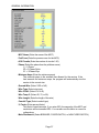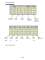
1
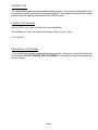
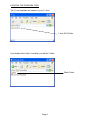
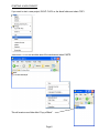
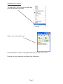
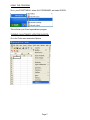
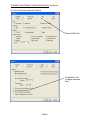
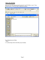
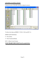
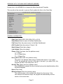
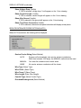
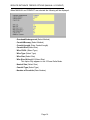
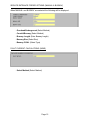
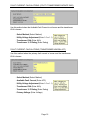
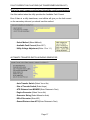
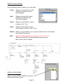
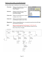
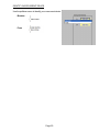
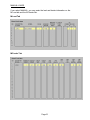
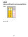
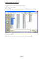
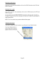
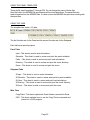
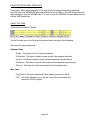
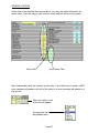
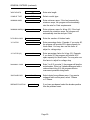
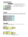
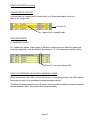
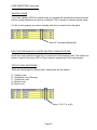
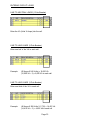
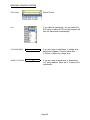
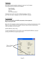
1-Line 2014
P
AP
R
E
OV
D
Copyright 2013
Durand & Associates
Page 1
User’s Manual
Load
Calculation
Software
1-LINE 2014
COPYRIGHT 2013 - DURAND & ASSOCIATES
This software and manual are protected by Federal Copyright Laws and may not be copied or
duplicated for the purpose of resale or distribution. A registered user may copy the template files
for their own personal use provided they retain sole possession of such copies.
The 1-Line 2014 software is a spreadsheet template software program for calculating main service
switchboard, subpanels, feeder sizes and 1-Line drawings. This program may be used for industrial
and commercial loads. The 1-Line 2014 software is for reference purposes only, and Durand &
Associates cannot assume any responsibility for the accuracy of the program contents. In using
this program the user agrees to hold harmless and wave all claims against Durand & Associates.
SOFTWARE REQUIREMENTS
1-Line 2014 was created with Microsoft Excel 97. To use these templates you must have Microsoft
Excel, Version 97 or later, installed on your computer.
If you are using Excel 2007 or later please use the 1-Line folder C:\1-Line 2014 Excel 2007
Page 2
INTRODUCTION
The 1-Line 2014 software is a spreadsheet template program. The program was designed for use
in conjunction with Microsoft Excel on the Windows platform. The program should also work on other
platforms that can read and write Microsoft Excel 97 file formats.
LOADING THE PROGRAM
Insert the CD in your drive and follow the setup instructions.
The installation of 1-Line will create the following folder on your C drive.
C:\1-Line 2014
EXPLORING THE PROGRAM
1-Line software is a complex spreadsheet template program. The program uses 53 files which link
to one another. DO NOT CHANGE THE FILE NAMES. If a file name is changed the template can
become corrupt.
Page 3
LOCATING THE PROGRAM FILES
The 1-Line templates are located on your C: drive.
1-Line 2014 Folder
If you double click on the 1-Line folder, you will find 1 folder.
Blank Folder
Page 4
STARTING A NEW PROJECT
If you want to start a new project, RIGHT CLICK on the blank folder and select COPY.
Then RIGHT CLICK on the white area of the window and select PASTE.
This will create a new folder titled “Copy of Blank”.
Page 5
RENAME THE FOLDER
You can RIGHT CLICK on the new folder and
select the RENAME command.
Type in your new project name.
Use this method to create a new project each time you start a new 1-Line.
Now that you have created a new folder close all windows.
Page 6
USING THE PROGRAM
Go to your START MENU, select ALL PROGRAMS, and select EXCEL.
This will start your Excel spreadsheet program.
TURNING ON AUTOMATIC UPDATING IN EXCEL
Go to the Tools menu and select Options
Page 7
TURNING ON AUTOMATIC UPDATING IN EXCEL (Continued)
Go to the Tools menu and select Options
Select the Edit Tab
Uncheck the “Ask
to update automatic
links.”
Page 8
USING THE PROGRAM
Select the FILE OPEN command and locate the 1-Line 2014 folder on your C: drive.
Double click the 1-Line 2014 folder to display the contents.
Now displayed are two folders.
1. Blank
2. Your New Project (This is the folder you just created.)
Page 9
EXPLORING THE SAMPLE PROJECT
Double click on the YOUR NEW FOLDER to display the contents.
The files in this folder are MSWBD, P1-P24, X1-X24, and MCC 1-4.
MSWBD ( Main Switchboard)
P1 - P24 (Panels)
X1 - X24 (Transformer/Panels)
MCC 1-4 (Motor Control Centers)
DO NOT RENAME THESE FILES (This will corrupt the files).
Page 10
WORKING WITH THE MAIN SWITCHBOARD (MSWBD)
Double click on the MSWBD file to display the Main Switchboard Template.
This may take a few seconds to open as Excel updates the links to the Panel files.
GENERAL INFORMATION
- Code Year (Select 2002, 2005, 2008, 2011 or 2014)
- Panel Name (Enter the name of the Main Switchboard)
- Fed From (Enter the power source for the Main Switchboard)
- # Of Circuits (Enter the number of Panels 1-24)
- High Voltage (Enter high voltage)
- Low Voltage (Enter low voltage)
- Phase (Select the phase from the pulldown menu)
1 = 1-Phase
3D = 3-Phase Delta
3Y = 3-Phase Wye
- Hi-Leg Size (Select size from pulldown menu)
This option only appears when using a 3-phase delta service. If you select
AUTO, the program will size the L2 (Hi-Leg) to the load. If you select FULL, the
program will size L2 the same as L1 & L3.
- Neutral Size (Select size from pulldown menu)
When MINIMUM is selected, the line to neutral load must be identified with an (N) in
the panel templates.
- Hertz (Enter Hertz)
- Minimum Amps (Enter the minimum amps)
The minimum amps is the smallest size allowed for the service. If the
load exceeds the minimum amps, the program will automatically size the
service to the correct size.
Page 11
GENERAL INFORMATION (continued)
- Minimum Amps L2 (Enter the minimum amps for L2)
This option only appears when using a 3-phase delta service and when AUTO
is selected for L2 (Hi-Leg). If the load exceeds the minimum amps,
the program will automatically size L2 to the correct size.
- Minimum Neutral Amps (Enter the minimum neutral amps)
This option only appears when AUTO is selected for neutral size. If the load
exceeds the minimum amps, the program will automatically size the
neutral to the correct size.
- % Factor (Enter percent factor)
This factor is used two ways. If you enter 20%, the ampacity of the panel and
conductors will be increased 20%. You can also use this factor to correct for
voltage drop.
- % Factor L2 (Enter percent factor for L2)
This option only appears when using a 3-phase delta service and when AUTO
is selected for L2 (Hi-Leg). This factor is used two ways. If you enter 20%,
the ampacity of the L2 conductor will be increased 20%. You can also use this
factor to correct for voltage drop.
- Main Breaker Sizing (Select method)
AUTO
Program will automatically size main breaker and feeder conductors.
When load exceeds 1200 amps, the MANUAL method must be used.
MANUAL
You enter the conductor and conduit size.
NONE
If you have seven (7) or more circuits, you must have a main breaker.
- Main Breaker Amps (Enter amps)
This option only appears when the main breaker sizing is set for MANUAL
- Main Breaker Position (Select position)
This option only appears when a main breaker is used.
DISPLAY OPTIONS
- Show Meter (Yes/No)
If YES is selected, a meter will appear on the 1-Line drawing.
- Show Current Transformer (Yes/No)
If YES is selected, a CT will appear on the 1-Line drawing.
- Show Fault Current (Yes/No)
If YES is selected, fault current will appear on the 1-Line drawing.
Page 12
DISPLAY OPTIONS (continued)
- Show Voltage Drop (Yes/No)
If YES is selected, voltage drop % will appear on the 1-Line drawing.
- Show Conduit Length (Yes/No)
If YES is selected, conduit length will appear on the 1-Line drawing.
- Show Ufer Ground (Yes/No)
If YES is selected, Ufer ground will appear on the 1-Line drawing.
- Show True Phase Connection (Yes/No)
If YES is selected, directories and panel schedules will display actual phase.
SERVICE ENTRANCE FEEDER OPTIONS (AUTO)
When AUTO is selected, the following will be displayed.
- Service Feeder Sizing (Select Method)
AUTO
Program will automatically size service entrance conductors.
When load exceeds 1200 amps, the MANUAL method must be used.
MANUAL
You enter the conductor and conduit sizes.
NONE
No service entrance conductors will be shown.
- Wire Type (Select Type)
- Wire CU/AL (Select Type)
- Wire Temp C (Select Temp)
- Wire Length (Enter Wire Length)
- Conduit Type (Select Conduit Type)
- Overhead/Underground (Select Method)
Page 13
SERVICE ENTRANCE FEEDER OPTIONS (MANUAL & CONDUIT)
When MANUAL and CONDUIT are selected the following will be displayed.
- Overhead/Underground (Select Method)
- Conduit/Busway (Select Method)
- Conduit Length (Enter Conduit Length)
- Conduit Size (Select Size)
- Wire CU/AL (Select Type)
- Wire Type (Select Type)
- Wire Size (Select Size)
- Wire Size (Hi-Leg) L2 (Select Size)
This option only appears in the 3-Phase Delta Mode.
- Neutral Size (Select Size)
- Conduit Type (Select Type)
- Number of Conduits (Enter Number)
Page 14
SERVICE ENTRANCE FEEDER OPTIONS (MANUAL & BUSWAY)
When MANUAL and BUSWAY are selected the following will be displayed.
- Overhead/Underground (Select Method)
- Conduit/Busway (Select Method)
- Busway Length (Enter Busway Length)
- Busway Size (Select Size)
- Busway CU/AL (Select Type)
FAULT CURRENT CALCULATIONS (NONE)
- Select Method (Select Method)
Page 15
FAULT CURRENT CALCULATIONS (UTILITY TRANSFORMER INFINITE BUS)
Use this method when the Available Fault Current is not known and the transformer
KVA is known.
- Select Method (Select Method)
- Utility Voltage Adjustment (Enter 1.0 or 1.1)
- Transformer KVA (Enter KVA)
- Transformer % Z Rating (Enter Rating)
FAULT CURRENT CALCULATIONS (TRANSFORMER KNOWN AFC)
Use this method when the primary fault current is known and the transformer
KVA is known.
- Select Method (Select Method)
- Available Fault Current (Enter AFC)
- Utility Voltage Adjustment (Enter 1.0 or 1.1)
- Transformer KVA (Enter KVA)
- Transformer % Z Rating (Enter Rating)
- Primary Voltage (Enter Voltage)
Page 16
FAULT CURRENT CALCULATIONS (NO TRANSFORMER KNOWN AFC)
This is the most common method and should be used in most projects.
Use this method when the utility provides the Available Fault Current.
Even if there is a utility transformer, most utilities will give you the fault current
on the secondary side and you should use this method.
- Select Method (Select Method)
- Available Fault Current (Enter AFC)
- Utility Voltage Adjustment (Enter 1.0 or 1.1)
AUTOMATIC TRANSFER SWITCH & ENGINE GENERATOR
- Auto Transfer Switch (Select Yes or No)
- Size of Transfer Switch (Enter Amps)
- ATS Distance from MSWBD (Enter Distance in Feet)
- Engine Generator (Select Yes or No)
- Generator Sizing (Select Manual or Auto)
- KW of Generator (Enter KW)
- Genset Distance from ATS (Enter Distance in Feet)
Page 17
IDENTIFY CIRCUIT LOADS
Use the pulldown menu to identify your circuit loads.
- Panel
When you choose Panel, all load
calculations forward from the
Panel Template.
- Xmfr
When you choose Xmfr, all load
calculations forward from the
Xmfr Panel Template.
- Space
When you choose Space, a space
is shown on the 1-Line.
- Spare
When you choose Spare a spare
circuit breaker is shown on the 1-Line.
- Manual When you choose Manual, you may input manual load on the M-Loads
tab and the M-Feeders tab.
- MCC
May be selected for the first four (4) circuits. C1, C2, C3, or C4
When you choose MCC, all load alculations forward from the
Motor Control Center Template.
SPARE or SPACE AMPS
When you select SPARE or SPACE, you need to
select the amp rating for each.
Page 18
IDENTIFY CIRCUIT LOADS - WITH METERS SHOWN
Use the pulldown menu to identify your circuit loads with meters.
- Panel w/m
When you choose Panel w/m, all load
calculations forward from the
Panel Template.
- Xmfr w/m
When you choose Xmfr w/m, all load
calculations forward from the
Xmfr Panel Template.
- Space w/m
When you choose Space w/m, a space
is shown on the 1-Line.
- Spare w/m
When you choose Spare w/m a spare
circuit breaker is shown on the 1-Line.
- Manual w/m
When you choose Manual w/m, you may input manual load on the M-Loads
tab and the M-Feeders tab.
- MCC
May be selected for the first four (4) circuits. C1, C2, C3, or C4
When you choose MCC w/m, all load alculations forward from the
Motor Control Center Template.
Page 19
IDENTIFY OVERCURRENT DEVICE
Use the pulldown menu to identify your overcurrent device
- Breaker
- Fuse
Page 20
MANUAL LOADS
If you select MANUAL, you may enter the load and feeder information on the
M Load tab and the M Feeder tab.
M Load Tab
M Feeder Tab
Page 21
LINKED FILES
The MSWBD file and all Panel files are linked back and forth. File links are only updated when
the files are open. If the file is closed and information is change, the closed file will not update
formula calculations. When this happens a link update color of orange will appear on your MSWBD
template.
Example
To avoid this you may want to open all active files.
(SEE NEXT PAGE)
Page 22
OPENING MORE THAN ONE FILE
Let’s say you have a main switchboard and 6 panels.
1. Start your Excel program.
2. Select Open
3. When the files appear, use the mouse to select the MSWBD files and P1-P6 files.
4. Then click on OPEN.
When these files are open, all linked formulas will update automatically.
Page 23
PRINTING LOAD CALCS
If you want to print the load calculations, click on the CALCS tab and use the FILE and
PRINT command.
PRINTING THE 1-LINE
If you want to print the 1-Line calculations, click on the 1-LINE tab and use the FILE and
PRINT command.
You may want to use the PRINT PREVIEW command to make sure the 1-Line fits on
the page. If it prints on more than one page, you may have to adjust the percentage (%)
under PAGE SETUP.
NOTE: The 1-Line printout may produce additional blank pages.
CREATING PDF FILES
If you wish to create PDF files of printouts, you will need to have Adobe Acrobat.
If you have Adobe Acrobat, a
Create Adobe PDF command
appears under the FILE menu.
Page 24
USING THE PANEL TEMPLATES
There are 24 panel templates P1 through P24. Do not change the name of these files.
Each file links to the MSWBD file and forwards all the load calculations. The panel files also
read information from the MSWBD files. It is best to have the MSWBD file open when working with
the panel files.
USING THE TABS
The template has twelve (12) tabs.
The first five tabs are for the Panel and the second five tabs are for the Subpanel.
Each tab has a special purpose:
Panel Tabs
Input - This sheet is used to enter information.
Schedule - This sheet is used to review and print the panel schedule.
Calcs - This sheet is used to review and print load calculations.
Directory - This sheet is used to review and print the circuit directory.
Errors - This sheet is used to review and print the errors.
Subpanel Tabs
S-Input - This sheet is used to enter information.
S-Schedule - This sheet is used to review and print the panel schedule.
S-Calcs - This sheet is used to review and print load calculations.
S-Directory - This sheet is used to review and print the circuit directory.
S-Errors - This sheet is used to review and print the errors.
Misc Tabs
Copy/Paste - This sheet explains the Paste Values command for Excel.
CAD - This sheet explains how to use the Copy Picture command and
paste into a CAD program.
Page 25
USING THE XMFR PANEL TEMPLATES
There are 24 XMFR panel templates X1 through X24 do not change the name of these files.
Each file links to the MSWBD file and forwards all the load calculations. The XMFR panel files also
read information from the MSWBD files. It is best to have the MSWBD file open when working
with the XMFR panel files.
USING THE TABS
The template has twelve (12) tabs.
The first five tabs are for the Panel and the second seven tabs are for the Subpanel
Each tab has a special purpose:
Subpanel Tabs
S-Input - This sheet is used to enter information.
S-Schedule - This sheet is used to review and print the subpanel schedule.
S-Calcs - This sheet is used to review and print subpanel load calculations.
S-Directory - This sheet is used to review and print the subpanel circuit directory.
S-Errors - This sheet is used to review and print the subpanel errors.
Misc Tabs
Copy/Paste - This sheet explains the Paste Values command for Excel.
CAD - This sheet explains how to use the Copy Picture command and
paste into a CAD program.
Page 26
GENERAL ENTRIES
Some cells in the template files are protected. You may only enter information into
certain cells. If you are using a color monitor, these cells are yellow or lime green.
Yellow Cells
Lime Green Cells
Each unprotected yellow cell requires a user entry. If an invalid entry is made, a RED
error message will appear to the left of the entry or an error message will appear in a
pop up box.
When you select a cell
a hint box will appear.
You may also use
the pulldown menu.
Page 27
GENERAL ENTRIES (continued)
Below is a list of valid entries for the general information section of the panel schedule.
PANEL
Enter the panel name such as LPA. If entry is
too long it may be cut off when printed. (As a
general rule 22 characters are allowed.)
P1
# OF CIRCUITS
30
Enter number of circuits. (Even number from
6 to 84) or use the pulldown menu.
PHASE
3Y
Enter phase. Note: You may put a 1-Phase
panel on a 3-Phase source.
HI-LEG SIZE
AUTO
Select Auto or Full. (3-Phase Delta Only)
NEUTRAL SIZE
AUTO
Select Auto or Full
Most of the time you will select Full and the neutral conductor will be sized the same as the line
conductor.
If you select auto you must identify each line to
neutral circuit with a (N) on the panel schedule.
MIN NET AMPS
60
You may enter zero and the program will calculate the proper wire size. You may also enter a
minimum value and the program will use the
minimum value. If the minimum value is less than
the neutral load, the program will size the neutral to
handle the neutral load. The program will size the
neutral to carry at least 34 percent of the line conductors per NEC requirements.
GND WIRE Y/N
Y
Enter Y or N.
If you enter Y, an equipment ground conductor
will be added to the feeder conduit(s).
WIRE TYPE
THHN
Select the wire type.
WIRE CU/AL?
CU
Enter CU or AL.
WIRE TEMP
75
Enter the wire insulation temperature.
Page 28
GENERAL ENTRIES (continued)
Enter wire length.
WIRE LENGTH
20
CONDUIT TYPE
EMT
Select conduit type.
MINIMUM AMPS
100
Enter minimum amps. If the load exceeds the
minimum amps, the program will automatically
size the wire for Code requirements.
MINIMUM AMPS (L2)
100
Enter minimum amps for hi-leg (L2). If the load
exceeds the minimum amps, the program will
automatically size the wire per Code.
KITCHEN LOADS
5
Enter the number of kitchen loads.
% FACTOR
20
Enter percentage factor. Example: If you enter 20,
the program will provide 20% spare capacity for
future loads. You may also use this factor to
adjust for voltage drop.
% FACTOR (L2)
20
Enter percentage factor for hi-leg (L2). Example:
If you enter 20, the program will provide 20%
spare capacity for future loads. You may also use
this factor to adjust for voltage drop.
MAIN BKR / FUSE
Y
Enter Y or N. If you enter Y, the program will size the
main breaker. If this is a 3-phase delta panel with a
reduced size hi-leg (L2), the program will size
overcurrent protection using fuses.
SUB PANEL BKR
3-PHASE
BREAKER POSITION
1, 3. 5
Select choice from pulldown menu. If you want a
subpanel fed from this panel, select 1-Phase
or 3-Phase.
If you have a subpanel, select the breaker position
from the pulldown menu.
Page 29
GENERAL ENTRIES (continued)
SHOW VD CALCS
YES
If you want voltage drop calculations to appear on
the load calculation printout enter YES.
You may enter any information in the green cells
and it will appear on the panel schedule.
DISPLAY ONLY
Also, in the general information section there are a group of cells displaying wire and conduit
size information. These cells only display information when no errors are present in the template.
CIRCUIT ENTRIES
Once you have completed the general entries, you may begin making the circuit entries.
Each circuit entry consists of the following:
BREAKER
Enter breaker type.
CIRCUIT DESCRIPTION
Enter circuit description.
Page 30
CIRCUIT ENTRIES (continued)
3-PHASE DELTA CIRCUITS
If you are entering 1-phase (line to neutral loads) on a 3-phase delta panel, do not put
them in the orange cells.
Hi-Leg (L2)
No 1-phase (line to neutral) loads.
LOAD IDENTIFIERS
H (HARMONIC LOAD)
On 3-phase wye panels, loads subject to harmonic currents (such as electronic ballast and
computer equipment) must be identified by placing an “H” in the harmonic identifier column.
Enter “H” or a space (Space Bar)
HOW THE PROGRAM CALCULATES HARMONIC LOADS.
When the harmonic load is 50% or more of the load ( on 3-phase wye panels), the, NEC requires
the neutral conductor to be considered a current carrying conductor.
Therefore, the feeder conduit has four (4) current carrying conductors and the conductor ampacity
must be derated to 80%. The program does this automatically.
Page 31
LOAD IDENTIFIERS (continued)
NEUTRAL LOADS
If you have selected AUTO for neutral sizing, the program will calculate the neutral load and
size the neutral separate from the line conductors. This is known as reduced neutral sizing.
For this to work properly you need to identify each line to neutral load in the panel.
Enter “N” or a space (Space Bar),
HOW THE PROGRAM CALCULATES NEUTRAL CONDUCTOR SIZE
In the auto sizing mode the largest line to neutral load is the ampacity used. The neutral conductor is sized on that load or 34% of line conductor ampacity per Code requirements.
CIRCUIT LOAD IDENTIFIERS
There are several ways to identify loads. Listed below are the options.
G - General Load
D - Receptacle Load (Diversity)
C - Continuous Load
K - Kitchen Load
M - Motor Load
Enter ( G, D, C, K, or M )
Page 32
ENTERING CIRCUIT LOADS
LINE TO NEUTRAL LOADS (1-Pole Breaker)
Enter the VA (Volts X Amps) into the cell.
LINE TO LINE LOADS (2-Pole Breaker)
Enter one half of the VA in each cell.
Example:
(50 Amps X 240 Volts) = 12,000 VA
(12,000 VA ÷ 2) = 6,000 VA in each cell
LINE TO LINE LOADS (3-Pole Breaker)
Enter one third of the VA in each cell.
Example:
(40 Amps X 208 Volts X 1.732) = 14,410 VA
(14,410 VA ÷ 3 ) = 4,803 VA in each cell
Page 33
SUBPANEL GENERAL ENTRIES
FED FROM
Select Choice
P1
If you select a transformer, you can select the
KVA rating or select AUTO and the program will
size the transformer automatically.
KVA
VD ADJUSTMENT
10
If you are using a transformer, a voltage drop
adjustment appears. Use this rather than
% Factor to adjust for voltage drop.
XMFR % Z RATING
10
If you are using a transformer, a transformer
% Z rating appears. Enter the % Z rating of the
transformer.
Page 34
PRINTOUTS
Each panel schedule template is designed to print out four (4) sheets
for the panel and four (4) sheets for the subpanel.
-
Panel Schedule
Load Calculation
Directory
Error Checking Report
Using the mouse, click on the tab to display the sheet you wish to
print. When the sheet is displayed, use the FILE/PRINT command.
NO COPY/PASTE
Do not use the COPY and PASTE commands on this template as
they can corrupt the file.
Each cell in this template has been formatted with error checking and performance codes.
When you copy a cell and use the paste command, these formats and performance
codes are pasted to the new location.
PASTE SPECIAL (Values Only)
To avoid corrupting the file use the COPY and the EDIT/PASTE SPECIAL command
selecting VALUES from the paste special menu.
Click on “Values”
and click OK.
Page 35
USING THE MOTOR CONTROL CENTER TEMPLATES
There are 4 MCC templates MCC-1 through MCC-4. Do not change the name of these files.
Each file links to the MSWBD file and forwards all the load calculations. The MCC files also
read information from the MSWBD files. It is best to have the MSWBD file open when working with
the MCC files.
USING THE TABS
The template has five (5) tabs.
Each tab has a special purpose:
Panel Tabs
Input - This sheet is used to enter information.
Calcs - This sheet is used to review and print load calculations.
AFC Calcs - This sheet is used to review and print the fault current calculations.
VD Calcs - This sheet is used to review and print the voltage drop calculations.
MCC 1-Line - This sheet is used to review and print the MCC 1-Line.
Page 36
GENERAL INFORMATION
- MCC Name (Enter the name of the MCC)
- Fed From (Enter the power source for the MCC)
- # Of Circuits (Enter the number of circuits 1-20)
- Phase (Select the phase from the pulldown menu)
1 = 1-Phase
3D = 3-Phase Delta
3Y = 3-Phase Wye
- Minimum Amps (Enter the minimum amps)
The minimum amps is the smallest size allowed for the service. If the
load exceeds the minimum amps, the program will automatically size the
service to the correct size.
- Ground Wire (Select YES or NO)
- Wire Type (Select wire type)
- Wire CU/AL (Select CU or AL)
- Wire Temp C (Select 60, 75, or 90)
- Wire Length (Enter the length of the wire)
- Conduit Type (Select conduit type)
- % Factor (Enter percent factor)
This factor is used two ways. If you enter 20%, the ampacity of the MCC and
conductors will be increased 20%. You can also use this factor to correct for
voltage drop.
- Main Disconnect (Select BREAKER, FUSED SWITCH, or NON-FUSED SWITCH)
Page 37
MOTOR INFORMATION
Enter motor
description.
Enter
Conduit
Length.
Select
Phase.
Select
Conduit
Type.
Select
Wire
Type.
Select
Motor HP.
Select
CU or AL.
END OF USER’S GUIDE
Page 38
Select
Overcurrent
Protection.
Select
YES or NO.
Select % of
FLA for
Overcurrent
Protection.
Select
Wire
Temp.
Select
YES or NO.