1
SECTION 4
STARTING
PRIOR TO USE, PLEASE ENSURE YOUR EXHAUST IS
TIGHTENED
Recommended procedure for tightening your exhaust pipe
Use a 14 mm spanner which has a ring spanner at one end and a
conventional open spanner at the other. Use the open-ended spanner to
remove the muffler. Slide the ring spanner along the exhaust pipe and
locate it over the exhaust pipe lock nut. Turn the exhaust pipe to the
desired angle and tighten the lock nut firmly. Slide ring spanner off down
pipe. Replace silencer and tighten locking nut with open-ended spanner.
Repeat the above operation with the engine warm so that the exhaust is
tightened when the threads are expanded and use the maximum amount
of thread.
If you need a different angled exhaust pipe, you can use one that is
suitable for other 4-stroke engines. RCV use standard exhaust thread
sizes: – 58CD = M11x0.75
GLOW PLUG CONNECTION
•
Use either a conventional clip on or remote glow plug connector.
disconnected although some drop in RPM may occur due to the rich
mixture and comparatively low engine temperature. Leave the engine
running like this for around 15 minutes. Stop it using the throttle and
allow it to cool for a further 15 minutes.
Now you can obtain the correct carburettor setting using the following
procedure:
a) Restart the engine, open the throttle wide and adjust the main
needle for just slightly rich (a few rpm short of peak).
b) Close the throttle to around 1/3rd and, with the engine at
around 6000 rpm, screw in the secondary needle until the
rough (rich) running smoothes out into a nice four-stroke note.
The needles are now ROUGHLY set but you will probably
have to richen the main needle on the throttle up to full power.
Test and adjust before returning to 6000 rpm.
c)
Reliable, slow running will not be achieved until the
engine has been run in for at least one hour. When this
running time has elapsed you can fine tune the idle needle.
NB. Close attention to the idle needle settings will pay
dividends in smoothness.
INSTALLING THE ENGINE IN A TEST STAND
•
•
•
WARNING. ENSURE YOU HAVE SECURELY FASTENED THE
ENGINE TO YOUR TESTSTAND
Ensure that the bench the engine is attached to will not be pulled
over by the thrust of the engine.
Fit a suitable sized quality propeller for running in. eg. APC type
12x6 (2-bladed propeller);
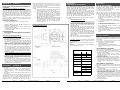
RCV58-CD Dimensions
STARTING METHOD
•
STARTING MUST ALWAYS BE CARRIED OUT WITH SAFETY IN
MIND. Use a conventional electric starter with a correctly sized cup
for your spinner.
TIPS & HINTS FOR STARTING PROCEDURE
1. Eye protection should always be worn when starting and running
your engine.
2. The crankshaft must be rotated anticlockwise (i.e.) the same
direction as normal propeller rotation
3. On a new engine or if very cold, the engine will feel quite stiff to the
turn and until the engine has had a tank or two of fuel passed
through it.
For initial starting purposes, we recommend needle
should be 2 turns open. This should be pre-set from the factory. At
all times ensure that the engine is on a low throttle setting when you
start it (1/8-1/4). High throttle will make the engine difficult to turn
over.
4. When you have set up the starting arrangement as described above
you can now start the engine. Ensure fuel is getting through to the
carb, and that the needle is open the correct amount. Turn the glow
on. Hold the starter very firmly but without pressing hard. Press the
starter button. The engine should immediately turn over rapidly and
fire within a few seconds.
5. Under No circumstances should you keep turning the engine
over if it does not fire as this may cause damage to the engine.
From the earliest prototypes the RCV engine has always been an
excellent starter. If the engine will not start there is always a logical
reason for it. In particular check that the glow is adequate, and that
fuel is getting through. If fuel doesn’t appear to be getting through,
unscrew the idle needle by a ½ turn.
6. If the starter will not turn the engine over remove the starter, turn the
glow off, turn the prop back to top dead centre, close the throttle
slightly to reduce the compression load on the starter, turn the glow
on and try again. If you do experience problems starting your engine
contact RCV and we will be happy to assist
SECTION 5
SECTION 6
SECTION 7
CARBURETTOR ADJUSTMENT
INSTALLING IN A MODEL
Main needle (high speed) adjustment: The main needle should be
adjusted with the engine operating at full throttle. The engine should be
leaned out until the RPM peaks, then enriched a small amount. This will
allow for the leaning out that normally occurs in flight.
If the engine is installed in a model, the nose of the model should be
raised to the vertical to check that the engine will run without leaning out
in this attitude. Note that to lean the engine out the needle is screwed in.
Idle needle (low speed) adjustment: If the engine does not run cleanly
at low or mid throttles the usual problem is that the idle needle is
incorrectly set. This can be adjusted with the small brass screw.
Please follow the guidelines below to decide how the idle needle should
be adjusted.
Idle Needle Adjustment Fault Finder
Idle mixture too lean: There will be a tendency for the engine
not to start at low throttle settings. Once it does start it will run
cleanly at mid throttle but will tend to die at low throttle. It will
also tend to die when the throttle is opened rapidly. In general
there will be little or no increase in engine speed when the
glow plug is energised.
Idle mixture too rich: The engine will start readily. It will run
roughly at mid throttle settings, and at idle will splutter and
pop. When glow is energised the engine will run more cleanly
and the idle will speed up considerably.
Idle mixture correctly set: The engine will start readily and
run cleanly from idle to max RPM. The idle will sound slightly
rich and “poppy”. Idle speed will increase slightly when the
glow is energised. The throttle can be opened rapidly without
the engine stalling.
NB. The idle mixture is sensitive, therefore increments of
1/8th of a turn or less are all that is normally required.
Factory Needle Settings
If you need to get back to the original factory needles settings,
please use the info below. This is only a starting point as there
is no hard fast rule.
Main Needle: Screw the needle in fully and then unscrew 1 3/4
turns
Idle Needle: Unscrew the needle fully out with the throttle open
and then screw in 3 1/2 - 4 turns
Measurements
in mm
RUNNING IN
The running in period on any engine is critical and will affect the lifetime
on your engine.
• The rotary cylinder valve design on your RCV58CD incorporates
close fitting components, therefore your engine will benefit from
extended running in (eg. 1 - 2 hrs). Power will also increase during
running in.
• Do not allow the engine to overheat during running in, therefore run in
short bursts.
Once the engine starts for the first time, leave the glow supply connected
and let the engine warm up at a fast idle speed for 30 seconds. Increase
the throttle setting to about ¼, and tune the high-speed needle valve for
slightly rich running i.e. a slightly burbling exhaust note (if you have a
tachometer aim for around 6000 rpm). The glow supply can now be
Issue 13
28/10/2008
58CD © RCV Engines Ltd
Page 2
This engine is subject to Global Patents and Design Copyrights inc. Int. Pat App. WO 03/062615
The RCV CD series produces a similar amount of power to a
conventional 4 stroke, therefore use the 4-stroke engine size as
recommended by your model kit manufacturer.
An RCV CD engine is designed to be mounted between
conventional beam mount engine bearer.
NB. The Prop shaft centre line is 3 mm above the bearer top face.
Ensure that this is taken into account when installing the engine
• Provide adequate cooling for the engine - a good guideline
to follow when deciding on the necessary air outlet / inlet
requirements is 2:1 or if possible 3:1.
This enables hot air to
escape from the cowl which is one of the main causes of
overheating.
•
•
•
•
•
•
The Carburetor may be rotated 180º to aid mounting
The engine can be mounted in any configuration including in an
inverted position.
The fuel tank should be installed with its centre line as near as
possible to the centre line of the carburettor.
We recommend using the fitting provided on the silencer to
pressurise the fuel tank
The crankcase breather is the same as on a conventional four
stroke. It cannot be used for fuel pressurisation and should simply be vented to the atmosphere
A piece of fuel tubing can be attached to crankcase breather –
max 6”"
SECTION 8
CARE OF YOUR RCV
NORMAL MAINTENANCE
At the end of each days flying it is recommended that a few squirts of
clean machine oil “after run oil” are introduced into the crankcase via the
crank breather.
If the engine is to be removed from the model and laid up for any
significant period, we recommend the following:•
Ensure there is no fuel left in the engine
•
Remove the glow plugs
•
Flush out the engine with good quality after-run oil
•
Store the engine on the plane with the nose down to keep oil in the
bearings
DISSASSEMBLING YOUR ENGINE
Specifications
Imperial
Metric
Displacement
0.58 cu in
9.5 cc
Weight
17.96 oz
550 g
Prop Shaft Dia
1/4” UNF
Exhaust Thread
M11 x 0.75
Mounting hole
size
3.5 mm
Practical rpm
2400 - 12000 rpm
2-blade Prop
sizes
11x6
11x7
12x6
Glow Plug
OS ‘F’
Approx. fuel
consumption
0.35 fl oz / min
RCV do not recommend disassembling your engine unless necessary. If
you do wish to do this, please follow the instructions below
1. Remove the carburettor, exhaust & the six socket headed screws
holding the crankcase together.
2. Separate the lower crankcase half and carefully remove the
crankshaft/piston assembly. Take care not to lose the small plastic pad
in the side of the piston.
To replace the front bearing :1. Remove the pop nuts, washer, prop driver & woodruff key.
2. The piston / conrod assembly is removed together with the bronze
thrust washer (note the big end position on reassembly).
3. The front bearing is a light press fit on the shaft and can normally be
removed by tapping the shaft down onto a soft material (ie. hard wood
or plastic).
RE-ASSEMBLING YOUR ENGINE
Reassembly is a simple operation & the main difficulty is ensuring that
the gears are engaged in the correct position so that the engine is timed
correctly.
1. Carefully remove any bearing lock material from the back bearing and
the crankcase halves.
2. Assemble the crankshaft piston assy in reverse order.
3. Take the cylinder jacket and rotate the cylinder until the cylinder port is
equally visible in the exhaust and inlet ports.
4. Now insert two cocktail sticks (or similar) into the exposed segments of
the port to lock the cylinder in position. Insert the piston into the
cylinder bore and engage the gears in such a way that the piston is at
top dead centre checking that the crankshaft webb is horizontal.
5. Apply a small amount of bearing lock onto each bearing and assemble
the bottom half of the crankcase with the six screws. Do not over
tighten these screws.
6. Remove the cocktail sticks.
Issue 13
28/10/2008
58CD © RCV Engines Ltd
Page 3
This engine is subject to Global Patents and Design Copyrights inc. Int. Pat App. WO 03/062615