1
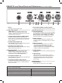
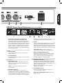
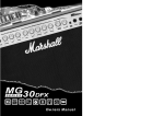
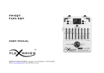
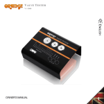
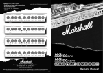
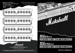
DSL
5C
5 Watt Combo
Dual Super Lead, All-Valve Combo
Owner’s Manual
DSL5C
5 Watt Combo
Sincere thanks and congratulations for selecting this Dual Super Lead, all-valve DSL5C combo.
As you may know, when the JCM2000 Dual Super Lead series of amps was first introduced in 1997,
we were delighted to see them get a fantastic reaction from guitar players and also the press. In fact
one of the biggest American guitar magazines described the DSL100 as “The best Marshall ever? It
combines the best tonal qualities and features of both modern and vintage Marshall amps in one package.” Better still, when the world renowned magazine, Guitar Player, reviewed the DSL100 it printed
“The Ultimate Marshall?” as a subheading on their June 1997 cover. After a very successful life, the
JCM2000 series was replaced by the JVM series in 2007, which has also gone onto great success
and critical acclaim. That said, there is still a great deal of respect and demand for the DSL’s with one
of the UK’s most popular guitar magazines recently referring to the DSL100 as “the go-to rock amp.”
As a result of public demand for the DSL’s tonal palate the late, great Jim Marshall decided to introduce a range of affordable amps based on the popular DSL100, one of them being your DSL5C.
We would like to wish you every success with all of your musical endeavours and also your DSL amp,
which We know will provide you with great tones and playing pleasure for many years to come.
Welcome to the Marshall family!
Yours Sincerely,
The Marshall Team
1
Overview
combined with the high gain settings of the
Ultra Gain channel. The Equalisation section
also features a Deep switch which adds a fixed,
resonant bass boost to your sound – adding girth
without muddying it up.
The mindset behind the DSL5C, 5-Watt combo
is a simple one – take that world renowned
DSL100H tone and make it available as a
compact, low wattage, all-valve unit containing 3
x ECC83 valves in the preamp and 1 x 12BH7 (or
ECC99) in the power-stage.
Enjoy your DSL amp and please read this
handbook carefully before plugging in.
Both channels share a passive three-band EQ
with controls for Bass, Middle and Treble. The
Equalisation section also features a Tone Shift
button which, when activated (pushed in), shifts
out the mid frequencies making the amp ideal
for brutal, modern metal tones, especially when
Follow all instructions and heed all warnings
KEEP THESE INSTRUCTIONS
Warning:
Before going any further, make sure that your amplifier is compatible with your electrical supply. If you have any doubt, please seek help
from a qualified technician – your Marshall dealer can help you in this respect.
Mains Input & Fuse:
Your amplifier is provided with either a detachable mains (power) lead which should be connected to the mains input socket on the rear
panel of the amplifier or a fixed mains (power) lead attached to the rear of the amplifier.
The specific mains input voltage rating that your amplifier has been manufactured for is indicated on the rear panel of the amplifier.
The correct value and type of mains fuse for valve amplifiers is specified on the rear panel of the amplifier.
NEVER attempt to bypass the fuse or fit one of the incorrect value or type.
Transporting your equipment:
Please ensure that your amplifier is switched off and unplugged from the mains electricity supply and that all removable cables have been
disconnected from your equipment before attempting to move it.
Important set up information:
1. Make sure that the cabinet(s)/speakers, where appropriate, are connected to the correct impedance LOUDSPEAKER jack(s) on the
rear panel of the amplifier. See the Speaker Output guides in this handbook, if applicable, for specific information regarding impedance
matching. When using an extension cabinet make sure that you are using a proper speaker cable. Never use a screened (shielded) guitar
cable for this purpose.
WARNING! Failure to do any of the above may damage your amplifier.
2. Ensure that the VOLUME controls on the front panel are set to zero.
3. For amplifiers provided with a detachable mains (power) lead, connect the supplied mains (power) lead into the MAINS INPUT on the rear
panel first and then into an electrical outlet.
4. Plug your guitar into the INPUT jack socket on the front panel.
5. Turn the front panel POWER switch on and, if a valve amplifier, wait a couple of minutes before going to point 6, other wise go to point 7.
6. Turn the volumes up to your preferred level and your amp is ready to play.
This equipment has been tested and found to comply with the requirements of the EMC Directive
EUROPE ONLY – Note:
(Environments E1, E2, and E3 EN 55103-1/2) and the Low Voltage Directive in the E.U.
EUROPE ONLY – Note: The average half-cycle r.m.s. inrush current, on initial switch-on, is 5.5 A. the average half-cycle r.m.s. inrush
current after a supply interruption of 5 s is 0.7 A
2
ENGLISH
The ability to select either the full 5 Watts of output
power or low-power (0.5-Watts) via the high/low
power switch on the rear panel, adds further to
your new DSL’s already impressive feature set.
The all-round tonal and gain versatility makes
your DSL5C superb and flexible performance tool
for today’s most demanding playing situations,
and you can rest assured it is packed full of our
famed Marshall tone.
The DSL5C features two footswitchable channels
(footswitch supplied) – Classic Gain and Ultra
Gain. As their names imply, each channel has a
very different character. Classic Gain takes you
from a shimmering, harmonic-enhanced clean
to a 1959 style crunch when the Gain control is
cranked. Ultra Gain, on the other hand, takes
you into the world of modern, high-gain and then
some.
DSL5C Front Panel Controls & Switches (from Left to Right)
3
2
1
5
6
7
8
7. ULTRA GAIN CHANNEL VOLUME CONTROL
Controls the volume level for the Ultra Gain channel.
1. INPUT
Input jack socket for guitar cable.
EQUALISATION SECTION ––––––––––––––––––––––––––
8. TONE SHIFT BUTTON
The Tone Shift reconfigures the tone network adding
a new dimension to passive tone shaping. When the
button is pushed in and the Middle control (10) is
turned down, the result is an aggressive, scoopedmid sound, ideal for many modern metal styles.
CLASSIC GAIN CHANNEL –––––––––––––––––––––––––
TONAL NOTE: This channel is based on the
“Clean” mode of the DSL100H’s Classic Gain
channel – producing a tone reminiscent of an early
1959 Plexi Super Lead head.
2. CLASSIC GAIN CHANNEL VOLUME CONTROL
Controls the volume level for the Classic Gain
channel. There is a level where the maximum clean
volume level is achieved, after this, the sound will
start to overdrive.
9. TREBLE CONTROL
Controls the high frequencies of the guitar tone,
making your guitar sound brighter when it is turned
clockwise.
3. CLASSIC GAIN CHANNEL LED
This LED lights-up green to indicate that the Classic
Gain channel has been selected.
10. MIDDLE CONTROL
This controls the middle register of your guitar’s
sound. Turning this up will make your guitar
sound fatter, while turning it down will result in a
sharper, “scooped” tone – especially when used in
conjunction with the Tone Shift button.
4. CHANNEL SELECTION BUTTON
Selects Ultra Gain channel when pushed in, and the
Classic Gain channel when out.
ULTRA GAIN CHANNEL – ––––––––––––––––––––––––––
TONAL NOTE: This channel is based on the
“Lead 2” mode of the DSL100H’s Ultra Gain
channel – producing a high-gain, mid-boosted
tone based on a hot-rodded JCM800 2203.
11. BASS CONTROL
Controls the amount of bottom end (low frequencies)
in your tone.
12. DEEP BUTTON
When pressed in, this switch adds a resonant
bass boost to your sound, increasing bottom end
thud while making your tone fatter around that
all-important low end. This is a function of the
power-stage.
5. ULTRA GAIN CHANNEL LED
This LED lights-up red to indicate that the Ultra Gain
channel has been selected.
6. ULTRA GAIN CHANNEL GAIN CONTROL
Controls the Gain level for the Ultra Gain channel. As
the amount of gain increases, so will the distortion
level in your sound.
(Gaps in table need filling)
4
POWER SECTION ––––––––––––––––––––––––––––––––––
13. POWER SWITCH
On/Off switch for mains power to the amplifier.
DSL5C Technical Specification
Size (mm) W450
H425
D253
Power (RMS)5W
Speaker1 x G10R-30 16Ω 10”
Weight (kg)4.8kgs
Valves
3 x ECC83 +
1 x 12BH7 (ECC99)
3
9
ENGLISH
9
10
11
12
13
DSL5C Rear Panel Features (from Left to Right)
1
2
3
1. MAINS INPUT SOCKET WITH MAINS FUSE
Your amp is provided with a detachable mains
(power) lead, which is connected here. The specific
mains input voltage rating that your amplifier has
been manufactured for is indicated on the rear panel.
Before connecting for the first time, please ensure
that your amplifier is compatible with your electricity
supply. If you have any doubt, please seek advice
from a qualified technician. Your Marshall dealer will
help you in this respect.
4
5
6
7
8
headphones to this jack when the power switch is set to
low, will mute the speaker for private practice.
6. AUDIO
Enables the connection of an MP3 player or any similar
source for practicing BUT ONLY when the amp is in
headphone mode (Low Power). The signals are mixed
using a HiFi mixer for high-quality, backing-track audio
quality - this does not effect the tone of the guitar signal.
IMPORTANT NOTE: The Audio in input is not
connected to the speaker - just the headphone out.
FX LOOP –––––––––––––––––––––––––––––––––––––––––
2. FX LOOP SEND
For connection to the input of an external effects
pedal or processor.
7. HIGH/LOW POWER MODE SWITCH
Switches the output power of the amplifier from 5W
(High) to approximately 0.5W (Low). It also effects
the operation of the Emulated Line Out/Emulated
Headphone Out (3) as already indicated.
3. FX LOOP RETURN
For connection from the output of an external effects
pedal or processor.
LOUDSPEAKER OUTPUTS –––––––––––––––––––––––––
IMPORTANT OPERATIONAL NOTE: With all-valve
amplifiers it is imperative that the amp is connected
to a load whilst in operation and that the impedance
output on the amp matches the total impedance of the
speaker cabinet being used.
Failure to comply with these points will result in
damage to the amplifier.
FOOTSWITCH –––––––––––––––––––––––––––––––––––––
4. FOOTSWITCH JACK
For the connection of the supplied footswitch. This
allows you to switch between the Classic Gain and
Ultra Gain channels.
NOTE: The footswitch overrides the front panel
Channel switch.
8. 16Ω SPEAKER OUTPUT
For the connection of the internal speaker or an
external 16Ω speaker cabinet.
5. EMULATED LINE OUT
A speaker emulated output for connection to a
recording console, live PA, or headphones. When the
Power switch (5) is set to High power, this jack operates
as a line output. When the power switch is set to Low,
the jack operates as a headphone output. Plugging in
IMPORTANT OPERATIONAL NOTE: The internal
speaker is 16Ω.
4
Notes
5
Notes
6
Denbigh Road, Bletchley, Milton Keynes MK1 1DQ England
Tel : +44 (0)1908 375411 Fax : +44 (0)1908 376118
www.marshallamps.com
Whilst the information contained herein is correct at the time of publication, due to our policy of constant improvement
and development, Marshall Amplification plc reserve the right to alter specifications without prior notice.
BOOK-91011