1
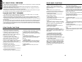
VALVE
SERIES
TEL: (01908) 375411
FAX: (01908) 376118
www.marshallamps.com
Whilst the information contained herein is correct at the time
of publication; due to our constant improvement and
development, Marshall Amplification plc reserve the right to
alter specifications without prior notice.
BOOK 00064 - 00
4100 DUAL REVERB
HANDBOOK
JCM 900
JCM 900
VALVE
SERIES
Marshall Amplification plc,
Denbigh Road, Bletchley,
Milton Keynes, MK1 1DQ
England
ENGLISH
WARNING! - Important safety instructions
WARNING: This apparatus must be earthed!
A
PLEASE read this instruction manual carefully before switching on.
B
ALWAYS use the supplied mains lead, if a replacement is required please contact your
authorised Marshall Dealer.
C
NEVER attempt to by-pass the fuses or fit ones of the incorrect value.
D
DO NOT attempt to remove the amplifier chassis, there are no user serviceable parts.
E
Refer all servicing to qualified service personnel including replacement of fuses and
valves. Servicing is required when the apparatus has been damaged in any way, such as
when the power supply cord or plug is damaged, liquid has been spilled or objects have
fallen into the apparatus, the apparatus has been exposed to rain or moisture, does not
operate normally or has been dropped.
F
NEVER use an amplifier in damp or wet conditions.
G
ALWAYS unplug this apparatus during lightning storms or when unused for long periods of
time.
H
PROTECT the power cord from being walked on or pinched particularly at plugs,
convenience receptacles and at the point where they exit from the apparatus.
I
DO NOT switch the amplifier on without the loudspeaker connected.
From the Chairman
I would like to thank you personally for selecting
one of our Marshall JCM 900 valve amplifiers. For
over three decades my company has been
dedicated to the design and manufacture of the
finest amplification systems in the world.
By ‘listening’ to guitarists from all over the world
we know that their needs are constantly changing,
demanding more from their amplification.
The only way to cope with these new demands is
to invest into the research & development of new
models capable of fulfilling their ever more extreme
requirements. This investment has led to
remarkable innovation within our product ranges
over the years.
In all the JCM 900 models there are degrees of
innovation to give extra high gain, wider tone
control and greater connection flexibility to provide
you with the widest possible sound variations.
In addition the incorporation of new circuitry and
the unique ‘output valve protection circuit’ has
increased the renowned Marshall reliability even
further.
I wish you great success with your new amplifier.
➲ Note: This equipment has been tested and found to comply with the requirements of the EMC
directive (Environments E1, E2 and E3) and the Low Voltage directive in the E.U.
➲ EUROPE ONLY - Note: The Peak Inrush current for the JCM900 4100 is 40 amps.
➲ CAUTION: Any changes or modifications not expressly approved by the party responsible for
compliance may void the users authority to operate the equipment.
➲ Note: It is recomended that all audio cables used to connect to the JCM900 4100 are of a high
quality screened type. These should not exceed 10 metres in length.
➲ WARNING: Do not obstruct ventilation grille and always ensure free movement of air around the
amplifier!
USA ONLY - DO NOT defeat the purpose of the polarised or grounding type plug. A
polarised plug has two blades with one wider than the other. A grounding type plug has two
blades and a third grounding prong. The wide blade or the third prong are provided for your safety.
When the provided plug does not fit into your outlet, consult an electrician for replacement of the
obsolete outlet.
Follow all instructions and heed all warnings
KEEP THESE INSTRUCTIONS !
1
2
ENGLISH
!
ENGLISH
REAR PANEL FUNCTIONS
The Dual Reverb range was designed for versatility with two independently controlled footswitchable
channels, each voiced totally differently.
Channel A is voiced for brilliant clean tones with the gain control (item 2) on lower settings and
crunch to lower gain lead as you turn it up.
Channel B is boosted with enough gain (item 3), for fearsome lead tones, ranging from classic on
lower settings to contemporary screaming solos on maximum.
Channel master volumes (items 9 & 11) and individual channel reverb controls (items 8 & 10) give
you incredible control and all round versatility in either, head or combo form.
1. Effects Loop Level Control
9 & 10. Valve Failure LED (OPV1-OPV4)
Valve Fuse (OPV1-OPV4)
Adjusts the level of the effects loop from 10dBV to + 4dBm. Higher settings match
modern effects processors and lower settings
match floor pedals.
In the case of output valve failure (OPV1OPV4), the fuse (item 10) will operate and
illuminate LED (item 9). The amplifier will
continue to function on reduced power (Using
OPV2-OPV3 Only). Service should be obtained
as soon as possible to prevent the premature
ageing of (OPV2-OPV3).
Note:
Some effects such as distortion and
compression are best suited to connection via
the front panel input as opposed to the loop.
VALVE OUTPUT POWER
2. Effects Send Socket
The JCM 900 range use high quality 5881 output valves (x2 in 50 Watt models, x4 in 100 Watt
models) for their unique distortion properties and fluid tone.
With most valve amplifiers, particularly Marshalls', the best sounds are achieved when the Master
Volumes are set high enough to be utilising the driving power of the output valves to the full.
This delicate working balance between the pre-amp and power amp levels can only be achieved by
experimentation.
You will find that all the JCM 900 models like to work hard and are designed to withstand prolonged
use at full power quite readily. The PB100 Power attenuator is ideal for this use (connects between
amp and cabinets) as it will allow you to run your amp at full power but keep the overall volume low.
The important thing to remember here is that it is the interaction between all the controls that plays
a part in achieving your sound.
Jack socket for connection to the input of
external effects processor.
11 & 12. Valve Failure LED (OPV2-OPV3)
Valve Fuse (OPV2-OPV3)
Similar functions to items (9) and (10) but
operating on OPV2 and OPV3.
3. Effects Return Socket
13. Mains Power Input
Jack socket for the connection from the output
of external effects processor.
Connects the amplifier to the mains power
supply.
4. Recording Compensated Line-Out
Socket
Note:
Always ensure that the incoming mains voltage
matches that of the amplifier. If in doubt consult
your Marshall dealer.
Jack socket for direct connection to recording
equipment or PA system. The signal is specially
filtered for optimum recording performance.
14. Mains Power Fuse
5. Direct Line-Out Socket
Protects the amplifier and mains supply in the
event of a fault.
Unfiltered pre-amp signal for connection to
external power amplifiers.
FRONT PANEL FUNCTIONS
Note:
6. Impedance Selector Switch
1. Input Jack
11. Master Volume Channel B
Connects the instrument to the amplifier.
(A high quality screened lead must be used).
Controls the overall volume level of Channel ‘B’.
12. Channel B ‘ON’ Push Switch/LED
2. Channel ‘A’ Pre-Amp Gain Control
Indicates red when Channel ‘B’ is selected
either manually or by remote footswitch (models
P802).
Sets the gain level for channel “A”. Lower
settings give clean sounds - higher settings for
medium drive and crunch rhythm.
13. Footswitch Jack Socket
3. Channel ‘B’ Lead Gain Control
Connects the remote dual footswitch (models
P802) for reverb ON/OFF and Channel A/B
switching.
Sets the gain level for boosted Channel B.
Lower settings give slight overdrive - higher
settings for maximum drive and sustain.
14. Standby Switch
4,5,6 & 7. Treble, Middle, Bass & Presence
Allows the amplifier to remain at ‘standby’ (i.e.
the valve heaters remain on, ready for instant
use, but without the signal circuit being active).
Passive rotary equalisation circuit. These
interactive controls provide a wide range of tonal
possibilities for both channels.
15. Power Switch
8. Reverb Control Channel A
On/Off switch for total mains power to the
amplifier.
Controls the amount of reverb on Channel ‘A’.
Always ensure that the fuse value matches the
labelling on the amplifier rear panel. If in doubt
consult your dealer.
Two-way switch for matching the amplifier to
speaker impedance. Amp heads feature 8 or 16
Ohm operation. Combo versions feature 4 or 8
Ohm options.
7. Loudspeaker Output Jack Sockets
Parallel wired jacks for linking speaker
cabinets. Ensure that the speaker system is
easily capable of handling the full amplifier
power and that the impedance (item 6) is
correctly selected. If in doubt consult your dealer.
8. Output Mode Switch
Switches the amplifier from high to low power
output. The “low” setting configures the output
stage to “triode” operation, which gives half the
rated output (i.e. 25 Watts on 50 Watts models or 50 Watts on 100 Watt models). The “high”
power position gives “pentode” operation for the
full rated output.
9. Master Volume Channel A
Controls the overall volume level of Channel ‘A’.
10. Reverb Control Channel B
Controls the amount of reverb on Channel ‘B’.
3
4
ENGLISH
HI GAIN DUAL REVERB
FRONT PANEL
MASTER
(CH. B)
PUSH ON
(CH. B)
0
JCM 900
1
FOOT
SWITCH
100W Hi Gain Dual Reverb
POWER
STANDBY
15
14
4
6
2
13 12
MASTER
(CH. A)
4
6
8 2
4
8 2
6
10
PREAMP
(CH. B)
4
6
4
8 2
6
8 2
4
6
8 2
4
6
8 2
4
6
8 2
8
PREAMP
(CH. A)
12
8 4
4
6
16 2
8
INPUT
0
10
0
10
0
10
0
10
0
10
0
10
0
10
0
10
0
20
0
VOLUME
REVERB
VOLUME
REVERB
PRESENCE
BASS
MIDDLE
TREBLE
LEAD GAIN
GAIN
11
10
9
8
7
6
5
4
3
2
Model 4100
1
REAR PANEL
EFFECTS
LINE OUTPUT
WARNING!:
POWER LEVEL OUTPUT
OUTPUT
VALVE FUSE
LOUDSPEAKERS
100W R.M.S.
IMPEDANCE
SELECT
Made in England by
FUSE
120V ~ 60Hz
375 Watts
220/240V - T2A
110/120V - T4A
T500mA
FAIL
FAIL
TION
Marshall Amplification plc,
Bletchley, Milton Keynes, England.
(4)16
HIGH
WARNING: DO NOT OBSTRUCT VENTILATION GRILLES
ATTENTION: NE PAS OBSTRUER LES GRILLES DE VENTILA
T500mA
MODE
MAINS INPUT
LOW
SEND
RETURN
LOOP
LEVEL
RECORDING
COMPENSATED
8
SHOCK HAZARD. DO NOT OPEN.
TO REDUCE THE RISK OF FIRE OR ELECTRIC SHOCK DO NOT EXPOSE THIS EQUIPMENT TO
RAIN OR MOISTURE. THIS APPARATUS MUST BE EARTHED.
AVIS!:
RISQUE DE CHOC ELECTRIQUE. NE PAS OUVRIR. POUR EVITER LES RISQUES
D’INCENDIE ET DE DECHARGES ELECTRIQUES, N’EXPOSEZ JAMAIS CET APPAREIL A L’HUMIDITE
OU A LA PLUIE. CONNECTER CET APPAREIL A LA TERRE.
CAUTION!: TO REDUCE THE RISK OF ELECTRIC SHOCK DO NOT REMOVE COVER.
NO USER SERVICEABLE PARTS INSIDE. REFER SERVICING TO QUALIFIED SERVICE PERSONNEL.
HIGH
ATTENTION!: POUR EVITER LES RISQUES DE DECHARGES ELECTRIQUES, NE PAS
OUVRIR LE COUVERCLE. CET APPAREIL NE COMPORTE AUCUNE PIECE SUSCEPTIBLE D’ETRE
REPAREE PAR VOS SOINS. FAITES TOUJOURS APPEL A UN TECHNICIEN QUALIFIE POUR TOUTE
REPARATION.
LOW
OPV-1-4
DIRECT
!
OPV-2-3
DO NOT USE WITHOUT CONNECTING SPEAKER LOAD
SEE MANUAL FOR CORRECT OPERATION AND RATING
OUTPUT: 100 WATTS RMS INTO 8Ω
1
2
3
4
5
6
7
8
9
10 11 12
13
14