1
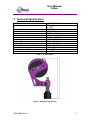
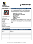
Unit 17 Denmore Industrial Estate, Denmore Road, Bridge of Don, Aberdeen AB23 8JW
User Manual
S-Box
This Manual Covers the Following Part Numbers:
100-3602-HV0
OPS-3602 Rev A
User Manual
S-Box
Table of Contents
Revision History ............................................................................................... ii
Safety.............................................................................................................. iii
1 Introduction ...............................................................................................1
1.1
General..............................................................................................1
1.2
Product Identification .........................................................................1
1.3
Declaration of Conformity ..................................................................2
2 Technical Specification .............................................................................4
3 Technical Description ...............................................................................5
3.1
Sheave Wheel and Bracket ...............................................................5
3.2
Packing Stick .....................................................................................5
3.3
Blow out plug .....................................................................................5
3.4
NPT Port Identification.......................................................................6
4 Operation ..................................................................................................7
4.1
Setting Up..........................................................................................7
4.2
Packing Stick fitting/replacement.......................................................7
4.3
Pre Job ..............................................................................................9
4.4
During Job .........................................................................................9
4.5
Post Job.............................................................................................9
5 Maintenance ...........................................................................................10
5.1
Introduction......................................................................................10
5.2
Schedule..........................................................................................10
5.3
Safety ..............................................................................................10
5.4
Tools................................................................................................11
5.5
Redress Procedure..........................................................................11
5.6
Maintenance Record Sheet .............................................................13
6 Testing ....................................................................................................14
7 Parts List and Drawings ..........................................................................15
8 Spares ....................................................................................................18
Table 1: Technical Data ...................................................................................4
Table 2: Maintenance Record ........................................................................13
Table 3: Parts List 100-3602-HV0..................................................................15
Table 4: Redress Kit Part No RDK-3602-HV0 ...............................................18
Table 5: Check Valve Redress Kit Part No RDK-2040-HV1 ..........................18
Table 6: Sheave Wheel Redress Kit RDK-2040-HN0 ....................................18
Table 7: Support Equipment ..........................................................................19
Figure 1: Stuffing Box Safety .......................................................................... iii
Figure 2: Technical Specification .....................................................................4
Figure 3: Wheel assembly ...............................................................................5
Figure 4: NPT Port Identification ......................................................................6
Figure 5: Stuffing Box Body Assembly...........................................................16
Figure 6: Stuffing Box Wheel Assembly.........................................................17
OPS-3602 Rev A
i
User Manual
S-Box
Revision History
Issue, Release Date
Rev A, 20 July 10
OPS-3602 Rev A
Description
Initial Issue
ii
User Manual
S-Box
Safety
WARNING: Trapped air requires considerable time to compress and
when it is compressed is highly dangerous. It has enough stored
energy to separate parts with considerable force.
All pressure equipment has a particular pressure rating and care must be taken to ensure that
no item is used in a situation that may cause its working pressure to be exceeded.
All personnel involved in pressure testing must be formally trained, competent and utilise the
appropriate PPE.
Safe-Lok devices should be checked for positional security to avoid unnecessary movement
of the collar.
Ensure the identification band/plate is fitted and is displaying the correct information
as per the Tag Sheet / Index
This equipment and the equipment it is attached to is heavy never position yourself below a
suspended load.
Caution: There are potential entrapment points at the tangent points between the Slickline
and the Sheave. All personnel must be warned to stay clear of these areas.
The Sheave Wheel is
detachable to allow
easier handling
Figure 1: Stuffing Box Safety
OPS-3602 Rev A
iii
User Manual
S-Box
1 Introduction
1.1 General
The Phuel S-Box introduces a truly innovative feature that ensures that Slickline
packing can be easily and consistently redressed. The S-Box is made up in three
sections to facilitate manual handling and to allow the tool string to be fed through the
top of the riser before make up.
This user manual serves as an introduction to the equipment and contains
specifications, operational, planning and maintenance instructions, parts list and
drawings.
1.2 Product Identification
Phuel products are identified by a unique serial number that provides full product
traceability. Each product is supplied with a documentation pack that contains
product certification and material/inspection reports. The serial number is always
etched on the surface of the product but can sometimes be difficult to find or read
after painting. A customer identification number is also included to allow the
customer to track the asset in their system.
A stainless steel band secures a nameplate tag that is stamped with the information
shown below.
PHUEL OIL TOOLS LTD
DESCRIPTION & SIZE
CUSTOMER ID No
PHUEL ID No 06-XXX-XX
MWP & SERVICE
TEST DATE
This tag should be located in the first instance to ensure that the manual issued refers to the
correct equipment
This equipment meets with the requirements of the Machinery Directive and the Equipment
and Protective Systems Intended for Use in Potentially Explosive Atmospheres Directive
(ATEX) and has the label above affixed to it.
OPS-3602 Rev A
1
User Manual
S-Box
1.3 Declaration of Conformity
DECLARATION OF CONFORMITY
Phuel Oil Tools Limited hereby declare that the following equipment
Model 100-3602-HVO Slickline Stuffing Box
Also described as;
A mechanical device used for guiding Slicklines (Wire-lines) into well bores while containing
well bore pressure (excluded from the Pressure Equipment Directive by virtue of Annex ‘A’ 6
and 9) and is manufactured to achieve the following specification.
Connections
6 ½’’ Acme
½’’ NPT
Maximum Working Pressure
10,000 Psi
Test Pressure
15,000 Psi
Maximum Line pull
2800 lbs/1270 Kg
Service
H2S
Working Temperature Range
-18 C to 121 C
Total Weight
122.5 lbs/55.56Kg
Overall Length (A)
40’’/1.02M
Make Up Length (B)
39’’/0.99M
Hydraulic Connection
½’’ NPT
o
o
Was found to be in accordance with;
The European Machinery Directive 98/37/EC being implemented in the United Kingdom
by the Supply of Machinery (Safety) Regulations 1992 and as amended by S.I. 1992/3073, S.I
1994/2063 and SI 2005/831
And the;
The European Directive on Equipment and Protective Systems Intended for Use in Potentially
Explosive Atmospheres 94/9/EC, being implemented in the United Kingdom by The
Equipment and Protective Systems Intended for Use in Potentially Explosive Atmospheres
Regulations 1996 (SI 1996/192) and as amended by The Equipment and Protective Systems
Intended for Use in Potentially Explosive Atmospheres (Amendment) Regulations 2001 (SI
2001 No.3766).
OPS-3602 Rev A
2
User Manual
S-Box
DECLARATION OF CONFORMITY
This equipment was designed to meet with the following European Harmonised Standards;
BS EN ISO 12100 Part 1 Safety of Machinery. Basic concepts, general principles for design
BS EN ISO 12100 Part 2 Safety of Machinery. Technical principles
BS EN 13463 Part 1: Non-electrical Equipment Intended for Use in Potentially Explosive
Atmospheres - Basic Method and Requirements.
BS EN 13463 Part 5: Non-electrical equipment intended for use in potentially explosive
atmospheres - Protection by constructional safety c.
BS EN 982 Safety of Machinery – Safety Requirements for Fluid Power Systems and Their
Components - Hydraulics
BS EN 1050 Safety of Machinery – Principles for Risk Assessment
This equipment has been classified as suitable for use within a potentially explosive
atmosphere as follows.
In addition to compliance with the aforementioned European Standards this equipment meets
the requirements of the following internationally recognised standards;
API 6A
I hereby declare that the equipment described in this document has been designed and
manufactured in compliance with the relevant sections and essential health and safety
requirements of the aforementioned Standards, Codes and Directives / Regulations.
Name
Colin McCracken
Position
Managing Director
Signed:
th
10 May 2010
OPS-3602 Rev A
3
User Manual
S-Box
2 Technical Specification
Part Number
Connections
Maximum Working Pressure
Test Pressure
Maximum Line Pull
Service
Maximum Working Temperature
Total Weight
Weight (Bracket)
Weight (Hub and Housing)
Weight Bottom Sub and Collar)
Overall Length (A)
Make Up Length (B)
Hydraulic Connection
100-3602-HVO
6 ½’’-4 Acme
½’’ NPT
10,000 Psi
15,000 Psi
3920 lbs/1782 Kg
H2S
-18°C to 121°C
122.5lbs/55.56Kg
35.5lbs/16.1Kg
44.8lbs/20.3Kg
42.2lbs/19.14Kg
40’’/1.02M
39’’/0.99M
½’’ NPT
Table 1: Technical Data
Figure 2: Technical Specification
OPS-3602 Rev A
4
User Manual
S-Box
3 Technical Description
3.1 Sheave Wheel and Bracket
The bracket is made up of a lightweight casting containing the solid
lightweight wheel and a quick release plunger arrangement to allow quick
fitting or changing of the slickline. The wheel assembly can also be separated
from the stuffing box assembly allowing easier handling.
Quick Release
Plungers
Figure 3: Wheel assembly
3.2 Packing Stick
The Phuel one-piece packing stick assembly allows for the quick change of
the packing stick. This can be achieved by simply pumping out the packing
stick using the piston and with the snap on capability can be quickly replaced
and drawn back in when the pressure is bled off.
3.3 Blow out plug
The blow out plug is incorporated so that in the event of a break occurring in
the slickline the valve will automatically seal containing the well pressure.
OPS-3602 Rev A
5
User Manual
S-Box
3.4 NPT Port Identification
Figure 4: NPT Port Identification
The two ½” NPT ports on the Stuffing box allow for the piston to be pressured
and for chemical injection. The ports are identified by hard stamping on the
housing but if this is difficult to make out then the ports are arranged so that
there is a difference in height between the two with the lower port being for
Chemical Injection. If the user is unable to determine the difference in the
height then the ports can be identified visually by looking into the actual port
and confirming the layout with the diagram above
OPS-3602 Rev A
6
User Manual
S-Box
4 Operation
All operations to be carried out by suitably qualified and competent
personnel
4.1 Setting Up
•
•
•
•
Check that the Sheave can freely rotate and that there is no obvious
bearing damage. Do not use the Sheave unless it freely rotates
Withdraw and lock the knurled plungers in the open position
Lay the slickline on the sheave wheel and lock the plungers back in
position
Feed the slickline through the wire bush and the Spacer, down through
the stuffing box until it emerges from the base. The Spacer selected
should suit the working pressure requirements – the steel one is for
high pressures and the brass one for lower pressure (6,500 psi max)
and has lower friction.
4.2 Packing Stick fitting/replacement
•
•
•
•
•
•
It is recommended to remove the Collar and Seal Housing from the
Housing and fit those parts to the top of the lubricator. This reduces the
handling weight and eases the assembly procedure. Place the Housing
in a vice.
Remove the check valve assembly by unscrewing the Check Nut from
the Housing
Pump out the piston so that the Piston Plug is visible
De-burr the end of the wire and pass it through the Wire Bush, Top Cap
and Spacer and then through the Piston plug until it appears at the
opposite side of the Housing. The Top Cap should be made up to the
Housing to prevent damage to the wire.
Disassemble the check valve assembly so that the wire can be pushed
through. There is no need to
remove the BOP Seat just make
sure that the ball is fitted and is
pushed to the side to allow the wire
to pass through. Slide the Blow Out
Plug onto the wire and push inside
the Check Nut so that it sits just at
the entry of the bore of the Check
Nut – do not push the thin fin fully
inside. Slide the BOP Retainer over
the wire and make it up to the
Check Nut.
Now make the check nut assembly
back up to the Housing taking care
OPS-3602 Rev A
7
User Manual
S-Box
•
•
•
•
•
•
•
•
not to bend the wire.
The rope socket can now be assembled to the wire. With no packing
yet fitted it will be easier to manage the wire and avoid any damage.
When ready to install the tool string into the lubricator – firstly push the
upper section of the tool string – weight bars and jars through the Seal
Housing that was fitted earlier (Step 1). Place the S-Box assembly on
the deck at a suitable distance to avoid bending the wire and make up
the rope socket to the top of the tool string. Since there is no packing
fitted yet the tool string should be pushed to near the bottom of the
lubricator section to make it easier to pull through and make up the tool
string. It is recommended that a length of string be attached to the
bottom of the tool string so that it can be pulled through if necessary as
the initial friction of the S-Box may appear higher than conventional
stuffing boxes.
Now make up the S-Box assembly to the Seal Housing.
When ready to fit the packing, remove the Top Cap and pump the
piston out.
Fit the two halves of the split packing together and ensure that the pegs
and holes are engaged. Follow the picture sequence overleaf to make
up the packing’s.
Ensure that the Top Cap is tightened up fully. A wrench will be required
for this – hand tight is not sufficient to allow the packing’s to take the
shape of the housing and to seal on the wire.
The bracket assembly can now be fitted and the two set screws used to
secure it in place
The wire is now ready to be clamped to the riser and the job can
continue as normal.
OPS-3602 Rev A
8
User Manual
S-Box
4.3 Pre Job
•
•
•
•
•
•
•
•
•
Ensure thread protectors are fitted
Check maintenance record sheet and ensure the equipment has been
maintained by competent personnel
Check all certification is in date
Confirm information band is fitted and correct
Ensure equipment is suitable for the maximum working pressures and
services involved
Ensure visible ‘O’ rings are seated correctly and there are no signs of
damage
Ensure threads are clean
Inspect for signs of damage
Pressure test to maximum well pressure
4.4 During Job
•
•
The Operator must check the temperature of the bearing area of the
sheave by hand if any unusual noise or operating conditions arise. If it
becomes intolerable to hold a bare hand on this area for 30 seconds
the temperature is likely to be in excess of 65°C and operations should
cease until an investigation into the source of the heat has been
performed.
Avoid excessive movement
4.5 Post Job
•
•
•
Inspect for signs of damage
Ensure threads are clean
Ensure thread protectors are fitted
OPS-3602 Rev A
9
User Manual
S-Box
5 Maintenance
All maintenance to be carried out by suitably qualified and competent
personnel
5.1 Introduction
Regular maintenance of the equipment using Phuel redress kits or Phuel
approved parts is essential to its continued safe operation. Ensure that the pre
and post job operating procedures are followed and that maintenance records
are kept.
5.2 Schedule
The maintenance schedule may be governed by international or company
standards and the following is considered to be the minimum requirements.
5.2.1 Pre & Post Job
Refer to Section 4.3 and Section 4.5 for details
5.2.2 Yearly
•
•
•
•
•
•
•
•
Disassemble Stuffing Box (see 5.5.1) clean and degrease all
components
Inspect the condition of all sealing surfaces and surface coatings
Re-coat threads and sealing surfaces if necessary. If in doubt contact
Phuel Oil Tools Ltd
Replace all elastomeric seals with items from redress kit (see spares
Table 4)
Regrease components
Re-assemble (see 5.5.2)
Pressure test to maximum working pressure in accordance to testing
procedure (see 6)
Inspect paint work and repair as necessary
5.2.3 Five Yearly
•
•
•
Yearly Maintenance (plus the following)
Carry out 100% surface NDE on all surfaces
Pressure test to test pressure witnessed by verifying body
5.3 Safety
•
Many of the components are heavy and should not be lifted without
lifting aids.
OPS-3602 Rev A
10
User Manual
S-Box
•
•
•
•
•
Ensure all pressure testing is carried out in the appropriate testing area
by suitably qualified personnel.
Wear appropriate personal protective equipment.
Do not over exert yourself while using torque wrenches. Use
appropriate mechanical advantages when available.
Ensure that all tools and equipment are in good condition and are
suitable for the intended use.
Clear up any fluid spills immediately to avoid slips.
5.4 Tools
The following tools are required:
• Memac Chain Wrench (No2 with 14’’ chain)
Other pipe wrenches may be used but will mark equipment
• ½’’ hex Allen key
• 3/8’’ hex Allen key
• ½’’ Spanner
• ¾’’ Spanner
• Pin punch
• Hammer
• Wire Brush
5.5 Redress Procedure
5.5.1 Dis-Assembly
•
•
•
•
•
•
•
•
•
•
•
•
•
•
•
•
Unlock the spring plunger L handle and remove the wheel assembly
from the bearing hub
Remove split cotter pin, bearing nut and bearing shaft from wheel
assembly
Remove wheel and knurled spring plungers from bracket
Remove BOP assembly from base of housing
Remove retainer, BOP plug BOP seat and ball bearing from check nut
Remove top cap
Remove washer and wire bush from top cap
Loosen packing housing and remove
Remove spring plunger L handle from lock nut. Loosen and remove
lock ring and lock nut
Remove tapered bearing, bearing hub and 2nd tapered bearing and
associated dust seals from housing
Remove spring, packing stick and piston from housing
Split seal housing and housing
Remove NPT plug, check valve spring and check valve from housing
Remove grease nipples from bearing shaft and bearing hub
Remove and discard all ‘O’ rings and ‘T’ seals
Degrease and clean all components
OPS-3602 Rev A
11
User Manual
S-Box
5.5.2 Re-Assembly
Prior to assembly, all parts should be carefully cleaned, inspected for any
signs of damage and greased.
•
•
•
•
•
•
•
Remove thread protection
Fit ‘O’ rings to the housing, seal housing, check nut and BOP seat
Fit ‘T’ seals to piston and packing housing
Fit ball bearing, BOP seat, Bop plug and retainer to check nut
Insert bearing into wheel centre
Fit the wheel into the bracket using the bearing shaft, bearing nut and
split cotter pin.
Fit 1/8 NPT grease nipple to bearing shaft
Note: Ensure the Sheave Wheel is greased by backing off the bearing
nut and pumping the grease then re-tighten the bearing nut. Failure to
do this will stop any grease from entering the bearing
•
•
•
•
•
•
Attach 3 knurled spring plungers to bracket
Insert lee plug into housing and using pin punch tap in until seated
Insert check valve seal, check valve spring and NPT plug into housing
Make up seal housing to housing and place collar over housing
Fit dust seal to tapered bearing and place on housing
Place bearing hub onto housing, fit 2nd tapered bearing and dust seal.
Fit lock nut and tighten in place. Fit grease nipple to hub
Note: Ensure bearing hub is correctly orientated and the threaded hole
on the locking nut aligns with the slot in the bearing hub
•
•
•
•
•
•
•
Fit lock ring and spring plunger L handle to lock nut
Fit packing stick to piston. Insert piston and spring into the housing
Insert packing housing into housing and tighten
Fit wire bush and nordlock washer to top cap and fit to packing housing
Fit BOP assembly to the base of the housing
Attach wheel assembly to bearing hub and fit spring plunger L handle
locking the assembly in place
After reassembly item is to be tested in accordance with the test
procedure Para 6 to maximum working pressure
OPS-3602 Rev A
12
User Manual
S-Box
5.6 Maintenance Record Sheet
Date
Type of
Performed
Performed Maintenance
By
Verified
By
Comments
Table 2: Maintenance Record
OPS-3602 Rev A
13
User Manual
S-Box
6 Testing
All testing is to be carried out in the designated test area and by suitably
qualified and competent personnel.
WARNING: Trapped air requires considerable time to compress and
when it is compressed is highly dangerous. It has enough stored
energy to separate parts with considerable force.
•
•
•
•
•
•
•
•
Fit appropriate test cap and blanks
Fill with testing fluid bleeding off any air within the system
Apply a pressure of 500 psi and ensure pressure holds for a minimum
of 10 minutes
Increase pressure to 10,000 psi (Maximum Working Pressure), allow to
stabilise and maintain this pressure until it is evident there are no
apparent leaks.(Testing to be carried out to Test pressure when
decreed by maintenance schedule)
Bleed off pressure, drain test fluid and dry
Remove test caps
Apply coating of de-watering solution to protect the bore and threads
Fit thread protectors
On completion of all maintenance ensure the maintenance record sheet (5.6)
is completed
OPS-3602 Rev A
14
User Manual
S-Box
7 Parts List and Drawings
Item
1
2
3
4
5
6
7
8
9
10
11
12
13
14
15
16
17
18
19
20
21
22
23
24
25
26
27
28
29
30
31
32
33
34
35
36
37
38
39
40
41
42
43
44
45
Part Number
100-1974-480
100-3603-480
145-3597-480
100-1975-480
100-2033-480
100-1977-B21
100-1986-316
100-1981-316
100-2526-B21
100-1979-B21
100-1988-B21
100-1980-B21
100-2037-ALU
100-2094-N66
100-1985-PU9
100-2514-PU8
802-1997-H80
802-1998-H80
802-1999-H80
801-0232-V90
801-0114-V90
801-0113-V90
801-0348-V90
100-2114-PEK
100-2527-B21
100-2212-STL
100-2005-STL
100-2211-316
100-2039-STL
100-2696-STL
100-3222-B21
100-2209-316
100-1943-304
100-2074-A69
100-2204-GSM
100-2205-316
100-2206-316
100-2207-STL
100-2208-304
145-2215-304
100-2179-STL
801-0155-N70
100-2692-STL
100-2693-STL
SDU-0503-HTS
SCU-0587-3A4
Description
HOUSING
SEAL HOUSING (6-1/2-4)
SOLID COLLAR (6-1/2-4)
PACKING HOUSING
TOP CAP
PISTON
LOCKNUT
LOCK RING
WIRE BUSH
CHECK NUT
BOP RETAINER
BOP SEAT
BEARING HUB
DUST SEAL
BLOW OUT PLUG
S-BOX PACKING STICK
ROD T-SEAL (.754 DIA)
PISTON T-SEAL (1.750 DIA)
PISTON T-SEAL (.750 DIA)
O-Ring - B.S Size 232
O-Ring - B.S Size 114
O-Ring - B.S Size 113
O-RING - B.S SIZE 348
CHECK VALVE SEAL
PISTON PLUG
COMP SPRING (C5511230)
LEE PLUG PLGA1560020A
BALL BEARING 0.250 DIA
TAPERED ROLLER BEARING (32012XA)
SPACER (FOR 10,000 PSI WP) - STEEL
SPACER (FOR 6,500 PSI WP) - BRASS
NPT SOCKET HEAD PLUG 1/8
SPRING PLUNGER L HANDLE LOCKING
SHEAVE BRACKET
SHEAVE WHEEL
BEARING SHAFT
BEARING NUT
ROLLER BEARING (NUP308-E-TVP2)
SPRING PLUNGER
SPLIT COTTER PIN 1/8 X 3 LONG
GREASE NIPPLE 1/8 NPT
O-Ring - B.S Size 155
OUTER SPRING
INNER SPRING (RIGHT HAND)
Set Screw Dog Point Size 1/4 Length 0.5 in
Set Screw Cup Point 1/2 UNC x 1.25 Long
Qty
1
1
1
1
1
1
1
1
1
1
1
1
1
2
1
2
1
1
1
1
1
1
1
1
1
1
1
1
2
1
1
1
1
1
1
1
1
3
1
2
2
1
1
3
2
Table 3: Parts List 100-3602-HV0
OPS-3602 Rev A
15
User Manual
S-Box
Figure 5: Stuffing Box Body Assembly
OPS-3602 Rev A
16
User Manual
S-Box
Figure 6: Stuffing Box Wheel Assembly
OPS-3602 Rev A
17
User Manual
S-Box
8 Spares
Use only spares supplied or approved by Phuel Oil Tools Ltd.
It is recommended that sufficient quantities of the following spares be
maintained to ensure that the equipment is always available when required.
Elastomeric spares are supplied in HNBR material as standard. Many other
materials are available please specify when ordering.
Part Number
802-1997-H80
802-1998-H80
802-1999-H80
801-0232-V90
801-0114-V80
801-0113-V90
801-0348-V90
Quantity
1
1
1
1
1
1
2
Description
ROD T-SEAL (.754 DIA)
PISTON T-SEAL (1.750 DIA)
PISTON T-SEAL (.750 DIA)
O-Ring - B.S Size 232
O-Ring - B.S Size 114
O-Ring - B.S Size 113
O-Ring - B.S Size 348
Table 4: Redress Kit Part No RDK-3602-HV0
Part Number
100-1979-B21
100-1988-B21
100-1980-B21
100-1985-PU9
801-0114-V80
801-0113-V80
100-2211-316
Quantity
1
1
1
1
1
1
1
Description
CHECK NUT
BOP RETAINER
BOP SEAT
BLOW OUT PLUG
O-Ring - B.S Size 114
O-Ring - B.S Size 113
BALL BEARING 0.250 DIA
Table 5: Check Valve Redress Kit Part No RDK-2040-HV1
Part Number
100-2207-STL
801-0155-N70
Quantity
1
2
Description
ROLLER BEARING (213 08 EITVPB C3)
O-Ring - B.S Size 155
Table 6: Sheave Wheel Redress Kit RDK-2040-HN0
8.1.1 Individual Items
Individual items may be ordered as required using the part number specified
Note: O-Rings conform to industry standards and may be substituted with
those from other suppliers -– at the sole risk of the user.
OPS-3602 Rev A
18
User Manual
S-Box
8.1.2 Support Equipment
The following support equipment is available on order from Phuel Oil Tools
Part No
900-2042-STL
Qty
1
Description
Test Blank
Table 7: Support Equipment
OPS-3602 Rev A
19