Transcript
19 ..28 VAC a 50 ..60 Hz
Typical: 2,5 W, Max: 3 W
Consumption
Z-PC
Z-PC Line
Line
30 ..90% a 40°C non condening
Altitude
Up to 2000 m a.s.l.
-20 ..+85°C
Protection
IP20
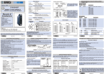
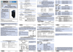
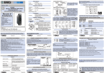
DIP-switch settings
The DIP-switches position defines the module Modbus communication parameters: Address
and Baud Rate. In the following figure the Baud Rate and Address values are listed as a
function of the DIP-switches position:
CONNECTIONS
Removable 3-way screw terminals, 3,5 pitch
Rear IDC10 connector for DIN 46277 rail
Connections
SIM connector in front & BD9-F in the side of module
Contents:
- General Specifications
- Optional Features
- Technical Specifications
- Installation Rules
- Electrical connections
- DIP-switch settings
- RS232 serial port
- Additional features
- Digital outputs
- Digital inputs
- Modbus connections rules
- Leds Signallings
- Accessories
DIMENSIONS / BOX
Dimensions
L: 100 mm; H: 112 mm; W: 17,5 mm
Box
PBT, Black
DIP SWITCH STATUS
RS485 address and Baud
Rate of serial communication
are settable from Dipswitches.
Dip-switches are disable
when the module
functioning as a modem
(default setting).
STANDARDS
The module complies with the following standards:
EN61000-6-4/2002-10 (electromagnetic emission, industrial environment).
EN61000-6-2/2006-10 (electromagnetic immunity, industrial environment)
EN61010-1/2001 (safety). All circuits must be isolated from the other cicuits
under dangerous voltage with double isolation. The power transformar must
comply with EN60742: «Isolated transformers and safety transformers».
EN 301 511 Harmonized standard for mobile stations in the GSM 900 and
1800 bands.
EN 301 489-1 ElectroMagnetic Compatibility standard for radio equipment
and services.
EN 301 489-7 Specific (EMC) conditions for mobile radio equipment (GSM
900 and 1800)
EN 60950 Safety of information Technology Equipment
SENECA s.r.l.
Via Germania, 34 - 35127 - Z.I. CAMIN - PADOVA - ITALY
Tel. +39.049.8705355 - 8705359 - Fax +39.049.8706287
For manuals and configurations software, see www.seneca.it
This document is property of SENECA srl. Duplication and reprodution are forbidden, if not authorized.
Contents of the present documentation refers to products and technologies described in it. All technical data
contained in the document may be modified without prior notice Content of this documentation is subject to
periodical revision.
MI001742-I-E
The conformity assessment procedure refeerred in article 10 and detailed in Annex
III of directive 1995/5/EC has been followed.
ENGLISH 1/8
Installation Rules
General Specifications
? RS232 serial port communication from DB9 on the side of the module
? RS232 with all handshaking signals.
? Modem GSM/GPRS on board.
? Set up module from DIP-switch.
2
? Removable screw terminals with section of 2.5 mm .
? 1500 Vac input isolation from rest of low-voltage circuits.
? Power supply and serial connection wiring facilitated by means of a bus that can be
housed on the DIN rail. However the screw terminal are still available.
? Insertion and extraction of a bus without interruption of communication or system power
supply.
? SIM card push-push connector on front.
Optional features
2 optoisolated digital input with external power supply from 12 to 30 Vdc.
? 2 optoisolated digital output shared negative pole collectively powered with external
power supply from 12 to 30 Vdc, current carrying capacity 50 mA.
? RS485 serial communication port with Modbus-Rtu protocol on the rear side of the
module for an easy connection on the Seneca bus up to 63 nodes and it is protected up to
30 Vdc.
?
Mosfet with shared negative pole
Maximum input range
50 mA / 50 Vdc
#2
10xxxxxx
38400
.....
.....
11xxxxxx
57600
xx111111
POSITION
BAUD RATE POSITION ADDRESS
xx000000
From EEprom xx000000
# 63*(N.B.)
From EEprom
PIN NAME DESCRIPTION
3
2
7
8
4
TX
Trasmitted data.
RX
Recived data.
RTS Request to send.
CTS Clear to send.
DTR Data terminal ready.
6
9
1
5
DSR
RI
DCD
GND
Data set ready.
Ring indicator.
Data carrier detect.
Ground.
30 Vdc
MI001742-I-E
Scheme 1
For the best performances, the use of special shielded cables is recommended
(BELDEN 9841 cable for example).
MODBUS RS485
Rear connector (IDC10)
Power Supply AC +
RS485 GND*
In the figure the meaning of the IDC10
connector pins is showed, in the case
the user decides to provide the signals
directly through it.
Power Supply AC-
RS485 A*
1
IDC 10
RS485 B*
ENGLISH 7/8
MI001742-I-E
LEDS Signallings
LED
STATE
Meaning of LEDS
PWR
FAIL
On
Blinking fast
Blinking slow
Power supply presence.
Searching network GSM
Docking to the network GSM
RS232
PU
ANTENNA
RS485
TS
19.. 28 Vac
10.. 40 Vdc
3W
M
M
CO
3
2
PO
2
3
TP
OU
PC user
S117P
Z-GPRS
In the figure the meaning of the IDC10
connector pins is showed, in the case
the user decides to provide the signals
directly through it.
ENGLISH 4/8
SU
PP
LY
Variations of standard parameters are possible by using configuration softwares EASY-ZPC (www.seneca.it).
For more information about a list of all regiater and their function consult the USER
manual.
FRONTAL INSERTING OF SIM CARD
IN THE PUS-PUSH CONNECTOR
Accessories
ANTENNA A-GSM
Z-PC-DIN2-17,5
Z-PC-DIN8-17,5
Z-PC-DINAL2-17,5
Terminals 2 and 3 can be used to provide the module with power
supply as an alternative to connection using the Z-PC-DINx bus.
The upper limits must not be exceeded as this can seriously
damage the module. If the power supply source is not protected
against overload, a safety fuse with a max. permissible value of 2.5
A must be installed in the power supply line.
MI001742-I-E
ER
S
UT
The RS485 interface, the digital inputs and the digital outputs can be used only after a
correct installation of application software.
The application software can be installed with seneca software configuration. EASY-ZPC.
For more information see the USER MANUAL avaiable on the site www.seneca.it
19 - 28 V
10 - 40 V
3 W Max
ENGLISH 2/8
2m
FUNCTIONAL DIAGRAM AND ISOLATIONS (1500 V)
Removable 3-way screw terminals [1,2,3]
Maximum input range
1200 m
W
INPUTS
2
Drop lenght
Bus lenght
ENGLISH 5/8
MI001742-I-E
IDC 10
Number of channel
Modbus connection rules
1) Install the modules on the DIN rail (max 120).
2) Connect the remote modules using cables of proper length. On the table the
following data about the cables length are provided:
-Bus Length: Modbus network maximum length as a function of the Baud rate. It is the
lenght of the cables which connect the two bus terminators modules (see Scheme 1).
-Drop Length: maximum length of a drop line (see Scheme 1) is 2 m.
Electrical Connections
1
With power supply from 12 to 30 Vdc
8
9
IN
Rear Connector (IDC10)
Type output
An external power supply from 12 to 30
Vdc can be connected to the input
V= 12.. 30 V terminal. All the inputs are connected in
shared connection to terminal 8 (GND).
Imax= 7 mA
The current that flows through a closed
#2
input is approx. 7mA.
Din2
#1
7
7
8
9
Power Supply AC-
2
#1
xx000010
PIN NAME DESCRIPTION
As it is illustrated in the next figure:
1) Insert the rear IDC10 connector on a DIN rail
free slot (the inserting is univocal since the
connectors are polarized).
2) Tighten the four locks placed at the sides of the
rear IDC10 connector to fix the module.
OUTPUTS
Type output
xx000001
19200
RS 232 serial port
Inserting on the DIN rail
Power Supply AC +
Number of channel
9600
01xxxxxx
DIGITAL INPUT
Din1
CONNECTION FOR MODEM CONFIGURATION
POWER SUPPLY
Technical specifications
00xxxxxx
RS232 has all the handshaking signals to allow the Z-GPRS to behave like a modem (by
sending AT commands). The meaning of the pins available on the DB9 connector, placed on
the side of the module, is shown in the following table.
The module is designed to be installed in vertical position on a DIN 46277 rail. In order to
ensure optimum performance and the longest working life, the module(s) must be supplied
adequate ventilation and no raceways or other objects that obstruct the ventilation slots.
Never install modules above sources of heat; we recommend installation in the lower part of
the control panel.
Optional functions are enabled when the application software has been installed in the
module.
Application software are downloadable from www.seneca.it
The application software can be installed with seneca software configuration: EASY-ZPC
BAUD RATE POSITION ADDRESS
*N.B. In this configuration the module operates as a MODEM using the RS232 serial port (for
AT command) and the antenna for GSM transmission. All the other function are disable.
ENGLISH 3/8
MI001742-I-E
POSITION
Dout2
LOAD
Installation
Manual
Vmax= 50 V
Imax= 50 mA
Load
+
Storage
Temperature
Load
10
11
12
GSM & GPRS
configurable module
with RS232 and RS485
-10 ..+65°C
Humidity
The state of outputs can be set from
Modbus register. The bit of register
represent respectively the value of
output (on / off). See USER MANUAL.
Resistive, inductive or capacitive loads
can be connected to the output
terminals.
Dout1
Z-GPRS
LOAD
Z-GPRS
Z-GPRS
mi
to ni-U
WI USB SB
RE
EN
ENVIRONMENTAL CONDITION
Temperature
DDBB
99 W
WII
RREE
Voltage
Additional features
DIGITAL OUTPUT
+
In case of Z-PC-DINAL2-17,5
accessory use, the signals may be
provided by terminal blocks. The
figure shows the meaning of the
terminals and the position of the DIPswitch (present on each DIN rail
supports listed on Accessories) for
network termination (not used in case
of Modbus network).
GNDSHLD: Shield to protect the
connection cables ( recommended).
10 ..40 VDC
DOWNLOAD APPLICATIONS FROM www.seneca.it
Z-PC-DINAL2-17,5 Accessory Use
POWER SUPPLY
External antenna GSM dual band swing with 3 m of cable
Expansion for DIN RAIL with 4 position, pitch 17,5
Expansion for DIN RAIL with 8 position, pitch 17,5
Support for DIN RAIL with screw terminals for communi-cation and power supply
Disposal of Electrical & Electronic Equipment (Applicable throughout the European Union and other European
countries with separate collections programs). This symbol, found on your producr or on its packaging, indicates
that this product should not be treated as household waste when you wish to dispose of it. Instead, it should be
handed over to an applicable collection point for the recycling of electrical & electronic equipment. By ensuring this
product is didposed of correctly, you will help prevent potential negative consequences to the environment and
human health, which could otherwise be caused by inappropriate disposal of this product. The recycling of materials
will help to conserve natural resources. For more detailed information about the recycling of the product, please
contact your local city office, waste disposal service of the retail store where you purchased this product.
MI001742-I-E
ENGLISH 6/8
MI001742-I-E
ENGLISH 8/8