1
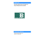
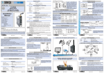
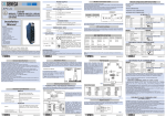
LinkBuilder FDDI Workgroup Hub User Guide Release Note
1
LinkBuilder® FDDI Workgroup Hub
User Guide Release Note
Part No. 09-0487-002/October 1993
This release note to the 3Com® LinkBuilder® FDDI Workgroup Hub User Guide
discusses the following topics:
■
■
■
■
Change in FCC compliance
Contents of the LinkBuilder diskette
Corrections in the User Guide
– Software-related
– Hardware-related
Replacing the fuse
Change in FCC Compliance
This notification of FCC compliance replaces the FCC compliance and
verification statements on page v of the LinkBuilder FDDI Workgroup Hub User
Guide. This notification acknowledges compliance with the limits for a Class A
digital device instead of a Class B digital device.
WARNING: This equipment has been tested and found to comply with the limits for a Class A digital device,
pursuant to Part 15 of the FCC Rules. These limits are designed to provide reasonable protection against
harmful interference in a commercial installation. This equipment generates, uses and can radiate radio
frequency energy and, if not installed and used in accordance with the instructions, may cause harmful
interference to radio communications. Operation of this equipment in a residential area is likely to cause
harmful interference, in which case, the user will be required to correct the interference at the user’s own
expense.
Changes or modifications not expressly approved by 3Com could void the user’s authority to operate this
equipment.
Contents of the LinkBuilder Diskette
The diskette shipped with the LinkBuilder FDDI Workgroup Hub contains the
following:
■
■
Backup copy of LinkBuilder FDDI system software image, version 1.0
Readme file
2
LinkBuilder FDDI Workgroup Hub User Guide Release Note
The system software has been preloaded into the hub management module flash
memory. Downloading the image to the FDDI Workgroup Hub disrupts the
ring. The download sequence isolates the hub from the ring during the poweron self-test (POST) and may cause the ring to wrap or to isolate attached
stations. Downloads impact the ring the least when the hub is attached to the
ring in a ring of trees configuration as a single attachment hub.
Corrections in the User Guide
The information provided in this section corrects software- and hardware-related
errors and omissions.
Software-Related Corrections
The corrections below are software corrections:
Page 2-14: Check the Baud Rate Setting After Post
When the power-on self-test (POST) is run, the hub’s serial port output defaults
to 9600 baud regardless of the baud rate setting in nonvolatile RAM. If you
have set the console baud rate to other than 9600, you may need to adjust the
attached terminal baud rate after POST has finished. The default baud rate
setting is 9600.
Page 2-14: Removing Modules
The first two steps for removing modules as given in the User Guide should be
reversed. They should read:
1.
Enter the disconnect command.
This disables all ports and isolates the hub from the ring.
2.
Disconnect all cables connected to the module that you want to
remove.
If possible, you should always turn off the power before attempting to remove or
insert hardware.
LinkBuilder FDDI Workgroup Hub User Guide Release Note
3
Removing modules from the hub with the power on will not damage the
hardware. However, the software may not be able to distinguish between
intentional removal and catastrophic failure of a media module. As a result,
some errors will be entered in the fault log and in some cases may fill the fault
log entirely. The most common error resulting from the removal of a media
module is 05000002 (bus error). Other errors may also occur. Check the fault
log for valid errors before you remove any module. Also, clear the fault log
(using the clear log command) after all changes are complete and the system has
been reinitialized.
Pages 3-9, 3-10, and 3-11: Accessing the Primitive Console
Command Mode
The procedure for accessing the primitive console command mode has been
modified. To access the primitive console command mode:
1.
Press the RESET button once, or enter the reset command.
During the subsequent power-on self-test (POST), the status LED flashes
amber/green for 10 seconds, indicating that the primitive console command
mode is being accessed.
2.
Press the RESET button again.
POST is reinitialized. When POST is completed, this prompt appears for
10 seconds:
Press Ctrl-P to enter Primitive console
All other keys except [Ctrl] and [P] are ignored during this 10-second
interval.
3.
Press [Ctrl] + [P].
The hub is now in the primitive console command mode.
If you do not access the primitive console command mode, POST executes the
system software resident in flash memory. Prior to execution of the system
software, POST verifies that flash memory is not corrupted. This process takes
about 20–30 seconds. During this time the status LED is off.
4
LinkBuilder FDDI Workgroup Hub User Guide Release Note
After flash memory has been verified, the status LED turns green when the
system is fully initialized. Within a short time, the modem initialization string
AT&F is briefly displayed. When the AT&F display disappears, you can access
the management console command mode by pressing [Enter].
When there is no active console session or if a console session times out, AT&F
will be displayed periodically to determine if a modem is present. You must
wait for the AT&F to disappear before pressing [Enter] to enter the management
console command mode.
Page 5-20: route dump and route add Commands
Changes have been made in the route command display and description. When
you enter the route dump command, a metric value appears in the subsequent
display, as explained below:
■
■
A metric of 0 indicates that the entry is a host.
A metric of 1 indicates that the entry is a gateway.
You can include a metric of 0 or 1 with the route add command. If you enter a
value greater than 1, it is converted to 1. If the metric is not entered, 1 is
assumed, which designates the entry as a gateway.
The default gateway, whether entered using the route add command or the set
gateway command, sets the metric to 1 regardless of the metric option given.
The metric option does not indicate the number of hops to the destination network,
as stated on page 5-20. It does indicate whether the entry is a host or a gateway.
Page 5-21: Fault Log Display
A reset count has been added to the fault log display header. When you enter the
show log command, the fault log header appears, as shown in the example below:
Fault Log:
[#
10]
The number corresponds to the number of times the hub has been reset and
allows you to correlate fault log entries with a given reset shown in the fourth
column of the display.
LinkBuilder FDDI Workgroup Hub User Guide Release Note
5
Page A-7: Management Module Failure Error Code
This a clarification of the management module failure error code. The management
module failure error code is 0xxxxxxx. If the second digit is 0 or 1 (that is, of the
form 00xxxxxx or 01xxxxxx), the error code indicates a nonvolatile RAM error or a
flash memory error on the management module, not a failure of the management
module itself.
Page C-22: show rev Command
This explains the length of time the show rev command takes to complete.
When you enter the show rev command in primitive console command mode,
the display verifies that flash memory is not corrupted before reporting the
firmware and software version strings. This process takes about 20–30 seconds.
Hardware-Related Corrections
The following section corrects errors relating to the wiring specifications for
UTP (unshielded twisted-pair):
Page 1-7: Media Flexibility
Under the Media Flexibility bullet, the UTP paragraph now reads as follows:
UTP media port module supporting level 5, data grade unshielded twisted-pair
(UTP) cabling system per the ANSI TP-PMD standard
6
LinkBuilder FDDI Workgroup Hub User Guide Release Note
Page 2-21: Unshielded Twisted-Pair Cable
Under the Unshielded Twisted-Pair Cable heading, the first paragraph now reads
as follows:
The standard UTP cabling type supported by the LinkBuilder FDDI Workgroup
Hub is Level 5 data grade media cable, for example, AT&T® type 2061, 1061,
or equivalent. Configure the cable as a cross-over cable with RJ-45 connectors,
as specified by ANSI X3T9.5. The cross-over cable connections are shown in
Figure 2-7.
Figure 2-7 is corrected, as shown below:
1
1
2
2
7
7
8
8
Figure 2-7. Cross-over Connections on a UTP Cable
Page 2-22: NOTE
The NOTE on page 2-22 applies to STP connectors, not UTP connectors. The
text of the NOTE, which is shown below, has not changed.
NOTE: To minimize RF emissions, the connector shell must be connected to hub
ground. Also, the connector shell must completely surround the cable shield.
LinkBuilder FDDI Workgroup Hub User Guide Release Note
7
Replacing the Fuse
If the hub’s LEDs are no longer lit, the unit may be disconnected from its AC
power cord. If the power cord is securely connected but the LEDs are still not
lit, the fuse probably needs to be replaced.
The fuse is located in the hub’s AC receptacle assembly and supplied as
standard equipment for the hub. It is a “quick-acting,” FSF034.1523 fuse or
equivalent, rated at 5 amps, 250 volts.
To replace the fuse, follow these steps:
1.
Locate the AC receptacle on the hub’s back panel.
2.
Disconnect the AC power cord.
3.
Carefully pry open and pull out the fuse-holder, as shown in Figure 1.
h 250
ly wit
n
Use o
e
V fus
avec
ment
nique
yer u le 250 V
lo
p
Em n fusib
u
Figure 1. Opening the Fuse-holder in the AC Receptacle Assembly
8
LinkBuilder FDDI Workgroup Hub User Guide Release Note
4.
Remove the burned-out fuse by pulling it straight out of its socket, as
shown in Figure 2.
h 250
ly wit
n
Use o
e
V fus
avec
ment
nique
yer u le 250 V
lo
p
Em n fusib
u
Figure 2. Removing the Fuse
If you wish, you can store a spare fuse in the front section of the fuse-holder.
5.
Insert a new fuse in the fuse-holder by reversing step 4.
6.
Push the fuse-holder back into the AC receptacle until it snaps in
place, and reconnect the AC power cord.
Once power is restored, the hub will reinitialize and run its power-on selftests (POST).
If the unit still does not power up, contact your network supplier.
© 1993, 3Com Corporation