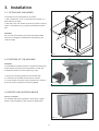
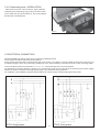
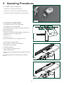
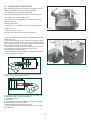
1
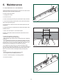
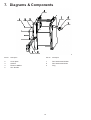
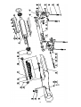
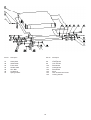
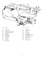
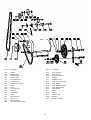
12" Planer/Jointer
Owner’s Manual
Model: 25-200
Record the serial number and date of purchase
in your manual for future reference.
Serial number:
Date of purchase:
For more information:
www.rikontools.com or [email protected]
For Parts or Questions:
[email protected] or 877-884-5167
Part # 25-200M1
Index
1
GENERAL INFORMATION
1.1 Foreword
2
MACHINE DESCRIPTION
2.1
2.2
2.3
2.4
2.5
2.6
2.7
2.8
Machine identification
Getting to know your planer/jointer
Technical specification
Recommended protective clothing
Noise emission
Prescribed use of the machine
Hazards
Safety instructions for the planer/jointer
3
INSTALLATION
3.1
3.2
3.3
3.4
Lifting and unloading
Position of the machine
Identifying shipping boxes
Installation of loose parts
3.4.1 Fence rail installation
3.4.2 Fence installation
3.4.3 Switch installation
Electrical connection
Dust chute - installation
3.5
3.6
4 ADJUSTMENTS
4.1. Planer table height adjustment
4.2. Infeed table height adjustment
4.3. Jointer fence adjustment
5
OPERATING PROCEDURES
5.1 ON/OFF switch
5.2 Jointer mode
5.3 Planer mode
6
MAINTENANCE
6.1 Replacing cutter knives
6.2 Drive Belt Check
7
DIAGRAMS & COMPONENTS
8
NOTES
2
1. General Information
1.1
FOREWORD
This manual must be read and understood before operating the machine. This will provide a better working knowledge of the
machine, for increased safety and to obtain the best results.
2. Machine Description
2.1
MACHINE IDENTIFICATION
There is a identification plate attached to the rear of the machine, containing machine data and serial number.
2.2
GETTING TO KNOW YOUR PLANER/JOINTER
2
3
5
4
8
7
9
1
6
10
1
Dust chute
6
On/off switch
2
Jointer fence
7
Locking level
3
Infeed table
8
Outfeed table
4
Height setting of infeed table
9
Cutterhead guard
5
Cutterblock
10 Height setting of the planer bed
3
2.3 TECHNICAL SPECIFICATION
SPECIFICATION
Feed speed sf/min
Cutterhead speed rpm
Cutterhead diameter
Max planer capacity
Max planing width
Max depth of cut jointer
Max depth of cut planer
Knives pcs
Fence tilting degree
Motor power output
Net Weight
25-200
23
5300
2.75"
12" x 8"
12.20"
1/8"
1/8"
3
0-45
3HP
386lbs
2.4 RECOMMENDED PROTECTIVE CLOTHING
•
•
•
•
Non-slip footwear is recommended.
Do not wear loose clothing, neckties or jewellery; they can be caught in moving parts.
Roll up long sleeves above the elbow.
Wear protective hair covering to contain long hair.
2.5 NOISE EMISSION
The measurements of noise, in the working position and during operation, were carried out under the standard ISO 7960 Annex B and C:
Instantaneous acoustic pressure:
Sound power level(no load)
<98dB(A)
Sound power level(load)
<107dB(A)
Sound Pressure level(no load) <89dB(A)
Sound Pressure level(load)
<98dB(A)
Constant K=4 dB measured in accordance with EN ISO 3746:1995
The figures quoted are emission levels and are not necessarily safe working levels. Whilst there is a correlation between the emission
and exposure levels, this cannot be used reliably to determine whether or not further precautions are required. Factors that influence
the actual level of exposure of the workforce include the characteristics of the work room and the other sources of noise etc. i.e.
the number of machines and other adjacent processes. Also the permissible exposure level can vary from country to country. This
information, however, will enable the user of the machine to make a better evaluation of the hazard and risk.
2.6 PRESCRIBED USE OF THE MACHINE
This machine is intended for edge jointimg and thickness planing of solid woods. The permissible workpiece dimensions must be
observed (see Technical Specification).
Any other use is not as specified. Unspecified use, modification of the machine or use of parts not tested and approved by the
equipment manufacturer can cause unforeseen damage.
2.7 HAZARDS
ATTENTION Planing and jointing still present risks that cannot be eliminated by the manufacturer. Therefore the user must be aware
that wood working machines are dangerous if not used with care and all safety precautions adhered to.
4
2.8 SAFETY INSTRUCTIONS FOR PLANER/JOINTERS
A planer/jointer is a tool which can, due to operator carelessness, cause serious personal injury. It is therefore strongly recommended
you read and observe:
· these instructions, particularly the special safety information in the respective chapters;
· the relevant guidelines or regulations for the prevention of accidents pertaining to the use of planer/jointers, where applicable.
Keep all documents, supplied with the machine, for future reference.
The planer/jointer shall only be started and operated by persons familiar with planer/jointers and who are at any time aware of the
dangers associated with the operation of such tool. Persons under 18 years of age shall use this planer/thicknesser only under the
supervision of an instructor in the course of their vocational training.
The following residual risks do principally exist with planer/jointers and can not, even by employing safety devices, completely
eliminated:
- Hazard generated by environmental conditions:
do not operate the planer/jointer in rain or damp environment. Ensure sufficient lighting. Do not
operate the planer/jointer near inflammable liquids or gases.
- Hazard to other persons in the work area:
Keep bystanders, particularly children, out of the danger zone.
- Risk of injury by machine faults:
check the planer/jointer for damage before any use. Do not operate the machine with a damaged part. Replace blunt cutter knives at
once. Risk of injury by kickback if a blunt knife gets caught in the workpiece's surface.
- Risk of injury by an unstable stand of the planer/jointer:
when working long stock use suitable supports on both sides of the machine. Avoid adverse body positions. Ensure firm footing, and
keep your balance at all times.
- Risk of injury by foreign objects in the machine:
prior to any starting of the machine ensure that there are no objects (e.g. tools) in the machine.
- Risk of injury by workpiece kickback (workpiece is caught by the rotating cutterhead and thrown back against the
operator):
operate machine only with a fully functional anti-kickback lock. Always use sharp cutter knives. If in doubt check workpiece for
inclusion of foreign objects (e.g. nails, screws, lose knots).
- Risk of injury by touching the rotating cutterhead:
always keep your hands well clear of the cutterhead. Switch machine off and plug out if it is not used.
- Danger! Drawing-in/trapping hazard!
Take care that no parts of the body or clothing can get caught and drawn in by the rotating cutterblock (do not wear neck ties and
garments with wide sleeves; contain long hair with a hairnet).
- Risk of injury by cuts with cutterblock at standstill: Wear gloves when changing cutter knives.
- Risk of injury by inhaling wood dust: dust of certain timber species (e.g. oak, beech, ash) can cause cancer when inhaled. Use a
suitable dust collector:
Risk of injury by inadequate personal protection: when planing, wear:
- dust respirator;
- hearing protection;
- safety goggles.
California Propsition 65 Warning
WARNING: Some dust created by power sanding, sawing, grinding, drilling, and other construction activities contains
chemicals known to the State of California to cause cancer and birth defects or other reproductive harm.Your risk from
exposure to these chemicals varies, depending on how often you do this type of work. To reduce your exposure, work in
a well-ventilated area and with approved safety equipment, such as dust masks that are specially designed to filter out
microscopic particles.
For more detailed information about California Propostion 65 log onto rikontools.com.
5
3. Installation
3.1. LIFTING AND UNLOADING
The machine can be transported by two means:
1. With a forklift truck. To do so, the machine is secured on a
pallet with four hex bolts.
2. With help. Here, the machine is carried by means of carrying
straps or two battens (A, Fig.1) placed underneath the planer
bed.
CAUTION
Do not move the machine by the infeed and outfeed tables,
these are not designed to withstand the tensile load by the
A
machine weight.
FIG. 1
3.2 POSITION OF THE MACHINE
CAUTION
It is prohibited to install the machine in explosive environments.
Ensure that the floor area around the machine is level, well
maintained and free from loose material e.g. chips;
1. Remove four mounting bolts from the machine base.
2. Lift machine off the pallet and set down on the floor.
3. Fix the machine to the floor. Fix the machine feet and fix on
ground by means of expansion bolts (not supplied).
FIG. 2
3.3 IDENTIFYING SHIPPING BOXES
BEFORE ASSEMBLY
It is advisable that before unpacking to have plenty of paper
towels or cloths available to clean off the rust preservative.
FIG. 3
6
3.4. INSTALLATIONS OF LOOSE PARTS
A
3.4.1 FENCE INSTALLATION
- To packaging, the fence seat (A, Fig. 4) is installed incorrectly
before shipment. Before installing the fence, taking off both of
the hex bolts (B, Fig. 4) and turn the fence seat 180 degrees.
B
FIG. 4
- Locate the lock level (C. Fig.5) from the loose bag and install it
onto the fence seat as Fig.5.
C
FIG. 5
- Slide the fence guide bar (D, Fig.6) into the fence seat and
locking through the level (C, Fig.6)
C
D
FIG. 6
3.4.2 SWITCH - INSTALLATION
H
- Fit the switch (G, Fig.7) onto the bracket with two hex nuts (H,
Fig.7)
FIG. 7
7
G
3.4.3 Cutterhead guard - INSTALLATION
- Take off both of the hex socket screws (A, Fig.8). Install the
B
cutterhead guard assembly (B, Fig.8) using two of hex socket
screws. Make sure the square washer (C, Fig. 8) stay between
the table and cutterhead guard.
C
A
FIG. 8
3.5 ELECTRICAL CONNECTION
Electrical installation should be carried out by competent, qualified personnel.
The connection should be made using the terminal box.
Ensure that the electrical supply corresponds with that of the machine, use cables of a section suitable for the power of the motor. For
an electrical supply of 230 V or a power rating greater than 15 A it will be necessary to increase the section of the connecting cables .
Connect the phase wires to the terminals R- S - T (L1 - L2 - L3) and the earth wire to the earth terminal.
On initial start-up check the direction of rotation, if it is incorrect then invert the two phase wires (for machines with 3 phase supply).
Direction of rotation of machines with single-phase supply is pre-determined during production .
On completion of the installation check that the terminal box is closed correctly and that the plug points are locked.
PT310 Single phase
8
PT310 Three phase
3.6. DUST CHUTE - INSTALLATION
A
The dust chute complete with suction connector must be
installed for planing.
CAUTION: The contact pins on the shaft of the dust chute (A,
Fig. 9) must engage properly in the limit switch. Incorrectly
installed dust chute the machine will not start.
Connect a suitable dust collector to the suction connector of the
jointer/planer.
FIG. 9
4. Adjustment
C
4.1. PLANER TABLE HEIGHT ADJUSTMENT
Per pass a maximum of 1/8" material can be removed.
Workpieces of max. 8" thickness can be planed.
D
Height adjustment is made with a handwheel (B, Fig.10). One
full turn of the crank changes the height of the planer bed (C,
Fig.10) by 5/32".
B
· Clockwise turning = raises the planer bed
· Counter-clockwise turning = lowers the planer bed. The planing
thickness is indicated on the scale (D, Fig.10).
FIG. 10
4.2. INFEED TABLE HEIGHT ADJUSTMENT
The infeed table (E, Fig,11) is adjusted by using adjusting lever
(G, Fig.11) for edge jointing and surface planing.
· The scale (F, Fig.11) next to the adjusting lever (G, Fig.11)
E
F
corresponds to 1/32" material removal.
H
- After adjustment, tighten ratchet lock lever (H, Fig.11)
- Per pass a maximum of 1/8" material can be removed.
G
FIG. 11
4.3. JOINTER FENCE ADJUSTMENT
The jointer fence (I, Fig.12) provides lateral support for the
workpiece when surface planing.
I
· After loosening the ratchet lock lever (J, Fig.12) the jointer
L
fence can be adapted to the workpiece width.
· After loosening the ratchet lock lever (K, Fig.12) & lock pin
(L, Fig.12) the jointer fence extrusion can be tilted to the angle
between 0°- 45°.
K
I
FIG. 12
9
J
5. Operating Procedures
5.1. ON/OFF SWITCH (Fig.13)
· To switch ON = press green switch button.
· To switch OFF = close cover or press red switch button.
· To unlock the switch cover push the pin on the stop cover.
FIG. 13
5.2 SURFACE PLANER MODE:
- The workpiece rests on top of the infeed table.
- The workpiece is cut on the underside.
- The feed direction of the workpiece is exactly opposite than
when thickness planing.
Workpiece dimensions
- Length: use a push stick to feed workpieces shorter than 12" ;
for workpieces over 60" use support rollers.
- Width: max. 12".
- Thickness: min. 1/4".
Note: The max. depth of cut for a single pass is 1/8".
FIG. 14
1. Assume proper operating position:
position yourself to one side of the infeed table.
2. Set jointer fence as required.
3. Set planing thickness.
4. Place workpiece against jointer fence .
5. Adjust cutterhead cover:
- when planing narrow edges (jointing) or workpieces more than
3" thick:
A
Set cutterhead guard from the side against the workpiece
(Fig16).
FIG. 15
FIG. 16
10
- Planing the face of a plank or workpieces up to 3" thick: lower
cutterblock cover from top onto workpiece. Adjust cutterhead
guard so that the undermentioned distances are not
exceeded in any position:
rear edge (A, Fig.17) – workpiece max. 1/64";
front edge (B, Fig.17) – workpiece max. 5/64".
6. Start motor.
Caution: The use of push blocks is necessary when face planing
thin material.
7. Turn the machine on and place the workpiece on the infeed
A
table. Feed the workpiece toward the cutterhead exerting
B
downward pressure until the workpiece clears the cutterhead on
the outfeed table side.
max. 3 mm
max. 2 mm
Note:
FIG. 17
Before using the jointer fence:
1. Set a try square (C, Fig.18) against the fence extrusion (D,
Fig. 18)
2. Loosen both hex bolt (E, Fig.18) and adjust the set screws (F,
Fig.18) until fence extrusion is square with the jointer table.
D
3. Tighten hex nuts when the fencn extrusion is exactly 90°
F
4. Set a mitre square against the fence extrusion.
C
5. Hex bolts (G, Fig.19) and adjust hex bolts until fence extrusion
is stopped exactly 45°.
FIG. 18
FIG. 19
11
E
G
5.3. THICKNESS PLANER MODE
A
Note: Thickness planing is used to reduce a workpiece with one
already surface planed surface to a desired thickness.
- The workpiece is run through the thicknesser.
- The surface already planed flat rests on the thicknesser bed.
- The workpiece is cut on the upper side.
- The feed direction of the workpiece is exactly opposite than
with surface planing.
Workpiece dimensions
- Length: min. 12"; for workpieces over 60" use roller support.
- Width: max. 12".
FIG. 20
- Thickness: min 12"; max. 8".
Note: The max. depth of cut for a single pass is 1/8".
1. Pull the jointer fence forward fully (Fig.20) and tighten the lock
handle (A, Fig.20)
2. Turn clamping lever (B, Fig.21) outward and swing the outfeed
table (C, Fig.21) together with the fence to the left. Make sure the
outfeed table lock (D, Fig.21) is engaged (When close the outfeed
table, please don't forget the release the lock).
3. Turn the dust chute (E, Fig.21) with installed suction connector
to the machine and secure with the lock pin (F, Fig.21).
4. Assume proper operating position:
- to feed the workpiece into the machine, position yourself offset
C
E
F
to one side of the feed opening.
D
B
FIG. 21
- to remove the workpiece from the machine, position yourself
offset to one side of the outfeed opening.
5. To thickness plane stock which surfaces are not parallel, use
suitable feeding aids (make fitting templates).
6. Set planing thickness.
7. Start motor.
8. Feed workpiece slowly and straight into the planer. It will then
be automatically fed through the planer.
9. Guide workpiece straight through the planer.
10. Switch machine off if no further cutting is to be done immediately afterwards.
12
6. Maintenance
6.1 REPLACING CUTTER KNIVES
CAUTION! Risk of personal injury by cuts from the cutter knives!
Wear gloves when changing cutter knives.
To remove the cutter knives:
1. Unplug power cable.
2. Push fence back.
3. Raise cutterhead guard fully and pull extrusion fully outwards.
FIG. 22
4. Turn the five hexagon head screws of the cutter knife lockbar
fully in wear gloves! (Fig.22).
5. At first remove cutter knife, then cutter knife lockbar from the
cutterblock.
6. Clean all surfaces of cutterhead and cutter knife lockbar with a
suitable solvent.
4 - 6 mm
7. Place new cutter knife on cutter knife lockbar.
8. Place cutter knife lockbar with the fitted cutter knife into the
cutterhead.
9. Check the projection of the knives:
- With the provided straight edge gauge .
- Place straight edge gauge across outfeed table and cutterhead
as shown.
- Turn cutterhead by hand one turn against the direction of feed.
- The cutter knives are set correctly if the straight edge is moved
forward 1/64" to 1/4" by the turning cutterhead. This check must
be performed the full length of the cutterhead. (Fig.23)
FIG. 23
10. To tighten the cutter knives, turn the five hexagon head
screws of the cutter knife lockbar fully out. To prevent distortion of
the cutter knife lockbar start with the screws in the centre , then
tighten the screws closer to the edges step by step.(Fig.24)
Danger!
- Do not extend tool when tightening the screws.
- Do not tighten bolts by striking the wrench.
11. Return cutterhead guard to its starting position.
12. Pull fence forward.
FIG. 24
13
6.2 Drive Belt Check
The cutterhead drive belt and the feedgear drive belt need to
be checked periodically and retightened if necessary. Both drive
A
belts are located behind the machine's side panel.
B
Checking the drive belt:
1. Unplug power cable.
2. Pull the fence (A, Fig.25) forward.
3. Take off the the side panel (B, Fig.25) and belt cover (C,
Fig.25).
C
FIG. 25
4. Check belt tension with thumb pressure. The drive belt should
not give more than 3/8" in the center.
Tensioning the drive belt:
5. From outside the machine, loosen the four nuts (D, Fig.26)
– using board (E, Fig.26) to increase the motor, the cutterhead
drive belt will be slackened.
CAUTION: When raising the motor with a board, don't damaged
the motor wiring box.
6. To tension the cutterhead drive belt, push the motor downward.
When belt tension is correct tighten motor mounting nuts (D,
Fig.26).
E
7. If necessary, remove chips and dust with dust collector or
brush.
D
8. Replace the side panel and belt cover secure with the screws.
FIG. 26
14
7. Diagrams & Components
Ref No.
Description
Ref No.
Description
1
2
3
4
5
Screw M6X12
Cover plate
Cabinet
Rivet nut M6X15
Hex. Nut M4
6
7
8
9
Pan head screw M4X60
Pan head screw M4X8
Plug
15
16
Ref No.
Description
Ref No.
Description
30
31
32
33
34
35
36
37
38
39
40
41
42
43
44
45
46
47
Extended dust port
Rivet
Bracket
Tube
Hex. Socket set screw
Adjusting washer
Anti-kickback finger
Shaft
Hex. Socket set screw
Rubber washer
Bearing
Cutter block
Knife
Knife locking bar
Special screw for locking bar
Spring
Mounting tube
Tube
48
49
50
51
52
53
54
55
56
57
58
59
60
61
62
63
64
Bearing bracket
Hex. Bolt M6X12
Hex. Bolt M8X30
Cutterblock bracket
Tighting rod
Spring
Hex. Nut M6
Flange nut
Outfeed roller
Infeed roller
Hex. Bolt M8X35
Roll pin
Spring
Cap nut
Dust collector
Carriage bolt
Flat washer
17
Ref No.
Description
Ref No.
Description
90
91
92
93
94
95
96
97
Flat washer
Scale plate
Infeed table
Front shaft
Handle shaft
Hex. Bolt
Lift bracket
Spring washer
97
98
99
100
101
102
103
104
105
Spring washer
Carriage bolt
Lock nut M8
Flat washer
Carriage bolt
Flat washer
Knob
Hex. Socket head screw
Locking handle
18
Ref No.
Description
Ref No.
Description
130
131
132
133
134
135
136
137
138
139
140
141
142
143
Screw M6X16
Right cover
Screw M6x40
Cutterblock guard assembly
Cutterblock guard w/cap
Infeed table
Left cover
Screw M6X12
Rotation label
Flat washer
Left bracket
Hex. Nut
Special bolt
Rear handle
144
145
146
147
148
149
150
151
152
153
154
155
156
Hex. Socket head screw
Retaining ring
Lock thead bar
Bracket
Hex. Nut M12
Hex. Nut M8
Hex. Socket head screw
Mounting base
Hex. Socket set screw
Flat washer
Hex. Bolt M8X25
Shaft
Set screw M6X8
19
Ref No.
Description
Ref No.
Description
170
171
172
173
174
175
176
177
178
179
180
181
182
183
184
185
Hex. Socket head screw
Guide shaft
Scale
Indicator
Thickness table
Mounting plate
Mounting tube
Threaded bar
Spacer block
Shaft tube
Hex. Socket set screw
Position plate
Lift chain wheel
Roll pin
Threaded bar
Screw M8X16
186
187
188
189
190
191
192
193
194
195
196
197
198
199
Bevel gear
Retaining ring
Shaft tube
Roll pin
Gear
Crank bar
Crank bar tube
Big handwheel
Hex. Nut
Handle bolt
Crank handle
Hex. Socket set screw
Drive chain
Chain wheel
20
Ref No.
Description
Ref No.
Description
220
221
222
223
224
225
226
227
228
229
230
231
232
233
234
235
236
V belt
Motor pulley
V belt A1194
Cap nut M8
Lock washer 8
Flat washer 8
Flange bolt M8X25
Motor
Chain
Lock nut M12
Bearing
Flat washer
Tube
Bolt M12X70
Key 6x16
Spindle pulley
Hex. Socket set screw
237
238
239
240
241
242
243
244
245
246
247
248
249
250
251
Lock nut M10
Flat washer
Big chain wheel
Washer
Retaining ring
Tube for chain wheel
Cam wheel
Cam wheel bracket
Cam wheel shaft
Flat washer
Shaft
Spring
V-blet pulley
Bearing
Bearing spacer
21
Ref No.
Description
Ref No.
Description
270
271
272
273
274
275
276
277
278
279
280
281
282
283
284
285
286
Cutterhead cover
Pan head screw M4x16
Sliding cover
Flat washer 4
Sliding cover bracket
Nylon nut M4
Jointer fence
Pin shaft
Pan head screw M4x8
Spring washer 4
Indicator
Scale
Square nut
Jointer fence bracket
Slider
Pin shaft
Spring
287
288
289
290
291
292
293
294
295
296
297
298
299
300
301
302
303
Rotation bracket
Pin stop knob
Hex bolt M6x30
Special washer
Tilt locking handle
Sliding locking handle
Sliding bracket
Hex bolt M8x25
Hex bolt M6x15
Stop bracket
Set screw M6x12
Hex bolt M8x12
Washer
Guide rail
Hex nut
Hex bolt M8x16
Warning label
22
Ref No.
Description
Ref No.
Description
330
331
332
333
Safety switch bracket II
Screw M4X30
Safety switch
Lock nut M5
334
335
336
337
Bracket
Small cam wheel
Hex. Socket set screw M5X35
Safety switch bracket I
23
8. Notes
24
2-Year Limited Warranty
RIKON Power Tools Inc. (“Seller”) warrants to only the original retail consumer/purchaser
of our products that each product be free from defects in materials and workmanship
for a period of two (2) years from the date the product was purchased at retail. This
warranty may not be transferred.
This warranty does not apply to defects due directly or indirectly to misuse, abuse,
negligence, accidents, repairs, alterations, lack of maintenance or normal wear and tear.
Under no circumstances will Seller be liable for incidental or consequential damages
resulting from defective products. All other warranties, expressed or implied, whether
of merchantability, fitness for purpose, or otherwise are expressly disclaimed by Seller.
This warranty does not cover products used for commercial, industrial or educational
purposes.
This limited warranty does not apply to accessory items such as blades, drill bits,
sanding discs or belts and other related items.
Seller shall in no event be liable for death, injuries to persons or property, or for
incidental, contingent, special, or consequential damages arising from the use of our
products.
To take advantage of this warranty proof of purchase documentation, which includes
date of purchase and an explanation of the complaint, must be provided.
To take advantage of this warranty, please fill out the enclosed warranty card and send it to:
RIKON Warranty
110 Cummings Park
Woburn, MA 01801
The card must be entirely completed in order for it to be valid. If you have any questions
please contact us at 877-884-5167 or [email protected].
25
For more information:
110 Cummings Park
Woburn, MA 01801
877-884-5167/781-933-8400
[email protected]
www.rikontools.com
Copyright Rikon Power Tools, Inc. 2009
Printed in China 3/09