1
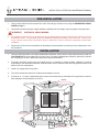
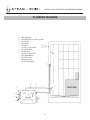
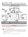
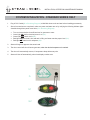
Mini Mist
Installation
Instructions
Health
Relaxation
Exhilaration
1
INSTALLATION, OPERATION & MAINTENANCE MANUAL
MODELS: MM-35, MM-50, MM-65, MM-75 and MM-90
MINI MIST SERIES
GUIDELINES FOR STEAM ROOMS
1.
Walls, ceiling and floor must be completely covered with waterproof finish; tile, marble, stone or slate.
2.
Any smooth surface flooring that is used such as tile or marble, should include an anti-skid finish to
avoid slipping and injury.
3.
Any exposed plaster, plasterboard or sheet rock surface must be well sealed with a commercial quality
waterproof sealer, urethane or epoxy, at least 3 coats.
4.
Use cement board, DO NOT use green board.
5.
Ceiling should be pitched away from the door 1-1/2” per foot or constructed in a gable configuration to
prevent condensation from dripping.
6.
Built-in seat should be slightly pitched to allow for condensation run-off.
7.
Steam room must be completely enclosed with walls, door, floor and ceiling, but should not be vapor
proof. A slight opening of approximately 1/4” is desired to create movement of the steam.
8.
A standard glass shower door is sufficient, a special door is not necessary.
9.
Make sure there is a floor drain for condensation run-off and cleaning.
10.
Do not install a fan inside steam room. Hot steam rises and will escape through the flapper.
11.
Windows that are part of the steam room enclosure should be double paned.
12.
If using lights inside steam room they must be vapor proof.
13.
A deionizer or inline filter hooked up on incoming water line is helpful in hard/corrosive water areas.
14.
Install the steam generator to hot side of water to reduce heating time, unless a water softener is
hooked up. Water softeners are usually hooked up to hot side.
15.
Check local utility line voltage and choose appropriate steam generator voltage; 208 Volt or 240 Volt.
16.
Make sure the steam generator is installed in an upright and level position and is in a location that is
ACCESSIBLE for Water Level Sensor Probe maintenance.
17.
Steam generator should never be located where it is exposed to outside weather conditions, freezing
temperatures, near flammable materials or inside the steam room.
2
INSTALLATION, OPERATION & MAINTENANCE MANUAL
CONFIRM THE CORRECT MODEL HAS BEEN SELECTED
1.
Multiply the length x width x height of the steam room enclosure (A)
A
Cubic Feet
2.
** If enclosure walls are constructed of glass, marble, concrete, stone B
or slate:
Copy the Figure from box (A) to box (B)
Cubic Feet
3.
Total (A) and (B) for total Cubic Feet (C)
C
Cubic Feet
4.
5.
INCREASE (C) FOR EACH OF THE FOLLOWING FEATURES OF STEAM ROOM ENCLOSURE
Add 15% for an exterior outside wall
D
Add 15% for each additional foot for rooms over 8’ high
E
Add 15% for an extra glass panel in addition to the door
F
Add boxes (C) through (F) for total Cubic Feet (G)
Select recommended model from the
GENERATOR SIZING GUIDE on Page 3
G
Cubic Feet
**
Certain materials used in the construction of steam rooms may require a larger unit
to produce the desired conditions. Consult an Architect, Designer, Contractor or the
factory to determine all factors necessary to build a suitable and safe steam room.
Larger Generators are available.
•
Steam-Whirl’s revolutionary LED self analysis system in the Standard Series generator
simplifies installation and monitors for proper electrical and water feed at all times.
•
All stainless steel tanks and components.
•
Extensive factory testing for all conditions.
•
6 year limited manufacturing warranty.
•
Factory assistance provided from blueprint to finished product.
3
INSTALLATION, OPERATION & MAINTENANCE MANUAL
GENERATOR SIZING GUIDE
ITEM#
92-92035
92-92050
92-92065
92-92075
92-92090
MODEL
MM-35
MM-50
MM-65
MM-75
MM-90
MAXIMUM
CUBIC
FEET
CAPACITY*
60
80
140
220
300
KW
VOLTS PHASE AMPS
3.5
5.0
6.5
7.5
9.0
240
240
240
240
240
1
1
1
1
1
15
21
27
31
38
BREAKER
SIZE
WIRE
SIZE
20A
30A
40A
40A
50A
12AWG
10AWG
8AWG
8AWG
8AWG
Mini Mist Series models contain (1) Steam Generator, (1) Accessory Kit,, Probe Maintenance Instructions and
Installation Instruction Guide
4
INSTALLATION, OPERATION & MAINTENANCE MANUAL
IMPORTANT SAFETY INSTRUCTIONS
When installing and using this electrical equipment, basic safety precautions should always be
followed, including the following:
1.
READ AND FOLLOW ALL INSTRUCTIONS
2.
WARNING
To reduce the risk of injury, do not permit children to use this product unless they are closely
supervised at all times.
3.
WARNING
To reduce the risk of injury:
4.
A.
The wet surfaces of steam enclosures may be slippery. Use care when entering or leaving.
B.
The steam head, steam line, plumbing and other components become extremely hot (+/- 212°F) during
operation.The steam head and plumbing must be installed in a location so that contact by user cannot
occur. Insulate plumbing lines for additional protection. The steam head is hot. Do not touch the steam
head and avoid the steam near the steam head.
C
After the system is shut down the components will remain hot. Do not come into contact with the steam
head or components until the system has returned to a normal temperature.
D.
Prolonged exposure to steam may cause hyperthermia. Hyperthermia occurs when the internal
temperature of the body reaches a level several degrees above the normal body temperature of 98.6°F.
The symptoms of hyperthermia include an increase in the internal temperature of the body, dizziness,
lethargy, drowsiness and fainting. The effects of hyperthermia include: Failure to perceive heat; failure
to recognize the need to exit the steam room; unawareness of impending risk; fetal damage in pregnant
women; physical inability to exit the steam room; and unconsciousness.
E.
Excessive temperatures have a high potential for causing fetal damage during the early months of pregnancy.
Pregnant or possibly pregnant women should consult a physician regarding correct exposure.
F.
Obese persons and persons with a history of heart disease, low or high blood pressure, circulatory system
problems, or diabetes should consult a physician before using a steambath.
G.
Persons using medication should consult a physician before using a steambath since some medication
may induce drowsiness while other medications may affect heart rate, blood pressure and circulation.
H.
The use of alcohol, drugs, or medication can greatly increase the risk of hyperthermia.
I.
Some aroma therapy oils may cause an allergic reaction - USE WITH CAUTION.
J.
The installation of a Steam Diffuser is recommended. This device will enable the user to move comfortably
around the steam shower and may help prevent burning or scalding.
K.
Always shut electricity off at the main breaker panel.
SAVE THESE INSTRUCTIONS
5
INSTALLATION, OPERATION & MAINTENANCE MANUAL
PRE-INSTALLATION
1.
Verify correct model has been sized for the cubic feet and type of steam room using the GENERATOR SIZING
GUIDE on Page 3.
2.
Check that the electrical power supply available is adequate for the voltage, amps and phase of the generator
warning
ELECTRICAL SHOCK HAZARD
3.
All installations and service must be performed by a qualified electrician and/or plumber and conform to all local
and national codes. The generator must be installed and operated according to the instructions. Failure to do
so will void the warranty and could lead to injury or death due to the live electrical components involved with
installation.
4.
Physical size of the unit and accessibility for plumbing service and Water Level Sensor Probe maintenance must
be considered.
INSTALLATION
1.
Place the steam generator in a location (heated attic, basement, vanity, closet or under shower bench) so that it is
ACCESSIBLE and not more than 40’ from steam room. All steam generators are suitable for operation in ambient
not exceeding 60°C/140°F. ALL steam generators require maintenance. **
2.
The steam generator should never be located where it is exposed to outside weather conditions or freezing
temperatures, near flammable materials, inside the steam room or where access cannot be gained to Water Level
Sensor Probe for maintenance.
3.
Install in an upright and level position.
4.
The serial number label should be visible and accessible for service.
5.
A minimum of 1’ of open unobstructed space must be left around the top and sides of the generator to allow for
heat dissipation and accessibility for service.
IN ATTIC
** IMPORTANT See #1 Above
TIMER CONTROL
IN CLOSET
STEAM-WHIRL
GENERATOR
STEAM BATH
MODEL NO
VOLTS
SER NO
AMPS
PH
KW
PRODUCTS
270-2124
MFG BY STEAM-WHIRL
NV 89118 (702)
LAS VEGAS
LISTED 16K3
STEAMBATH
EQUIPMENT
C
®
US
LISTED
(Behind Shower Wall)
** IMPORTANT See #1 Above
IN VANTITY
** IMPORTANT See #1 Above
6
IN BASEMENT
** IMPORTANT See #1 Above
INSTALLATION, OPERATION & MAINTENANCE MANUAL
PLUMBING
IMPORTANT:
All plumbing should be done by a qualified plumber and must conform to all local and
national plumbing codes.
warning
ELECTRICAL SHOCK HAZARD
POWER MUST BE DISCONNECTED AT THE MAIN ELECTRICAL SUPPLY BEFORE MAKING ANY CONNECTIONS
1.
Use copper or brass fittings only. DO NOT use galvanized or black iron.
DO NOT USE PLUMBERS PUTTY ON ANY WATER CONNECTIONS
2.
A union must be installed close to the generator to facilitate easy removal, if necessary.
3.
Tap off any existing water supply line, hot or cold, with 1/2” copper tubing or 1/2” NPT pipe. If hot water line is used
temperature should not exceed 160°F. The maximum water pressure should not exceed 120 psi.
4.
Flush at least 1 gallon of water to clear line prior to connecting to the 1/4” compression water inlet fitting
(A in Plumbing Diagram) on generator. When tightening this fitting, use two wrenches to avoid strain on Water
Solenoid Valve inside generator.
5.
Install a shut-off valve (B in Plumbing Diagram) on the water supply line as close to the generator as possible.
DO NOT USE A SADDLE VALVE
6.
For best results install an inline filter between the shut-off valve and generator.
7.
For best results, steam generator should be higher than the steam head. If this is not possible, steam line must
slope 1/4” per foot minimum to steam room.
8.
Connect 1/2” copper tubing or 1/2” NPT pipe to steam outlet (C1 in Plumbing Diagram) for left or right side
installation or (C-2 in Plumbing Diagram) for top installation and run to approximately 8-12” off finished floor
in shower or just above deck of bathtub on any wall not interfering with user and at least 12-14” away from seat
or bench. For areas with acrylic or other non-heat resistant floors, install steam head 20-30” off finished floor in
shower.
DO NOT PLACE A SHUT-OFF VALVE ON STEAM OUTLET LINE, ONLY ON WATER SUPPLY LINE.
WARNING: DO NOT PLUMB VALLEYS AND DIPS WHERE WATER FROM STEAM CONDENSATION IN THE
LINE COULD COLLECT AND CAUSE BLOCKAGE.
9.
Leave approximately 1/2” of threads protruding from finished wall. Place escutcheon on threads and screw on
steam head (D in Plumbing Diagram). Take care not to scratch the steam head with wrench. Rotate steam head
until open slot is facing down.
10. IMPORTANT: Steam head must be installed to prevent users from coming into direct contact with the steam head
and the steam coming from it. While in use the steam head and steam coming directly from it will become hot and
can burn. An optional Steam Diffuser is recommended for small steam rooms.
11. Connect 3/4” copper tubing or NPT pipe to the pressure relief valve (E in Plumbing Diagram). This item must
be installed with a union and plumbed to drain to an approved location.
DO NOT PLUMB THE PRESSURE RELIEF VALVE LINE TO THE STEAM LINE OR INTO THE STEAM
ROOM.
7
INSTALLATION, OPERATION & MAINTENANCE MANUAL
PLUMBING DIAGRAM
(A)
(B)
(C1)
(C2)
(D)
Water Supply Line
Shutoff Valve-As close to unit as possible
Steam Outlet
Steam Outlet
STEAM
Steamhead
Locate 8” to 12” above floor
ROOM
(E) Pressure Relief Valve
(F) Mini Mist Timer
Locate 4’ to 5’ above floor
(F) LED Indicator Window
(H) RJ11 Cable to Timer
(I) Wiring Junction Box
L1, L2 & Ground Pigtail
(F)
(C2)
(G)
(D)
(E)
(H)
(C1)
(B)
(I)
(A)
8
INSTALLATION, OPERATION & MAINTENANCE MANUAL
GENERATOR DIAGRAM
Water Supply Line
1/4” Copper Line, 1/4” NPT Femal Thread
Steam Output Line
1/2” Copper Line, 1/2” NPT Femal Thread
Pressure Relief Valve
3/4” Copper Line, 3/4” NPT Female Thread, Valve Supplied
ELECTRICAL
IMPORTANT:
All wiring should be done by a qualified electrician and must conform to all local and
national electrical codes.
warning
ELECTRICAL SHOCK HAZARD
POWER MUST BE DISCONNECTED AT THE MAIN ELECTRICAL SUPPLY BEFORE MAKING ANY CONNECTIONS
1. Supply wiring should be sized in accordance with the distance, voltage and amps of the unit and suitable for 90°C.
Bring supply wires from Wiring Junction Box (I in Plumbing Diagram) to L1 and L2 and the ground to the ground
terminal.
2. Install a power disconnect near unit.
3. Install Timer (F in Plumbing Diagram) according to Timer Installation Instructions.
9
INSTALLATION, OPERATION & MAINTENANCE MANUAL
MINI MIST SERIES WIRING DIAGRAM
POWER
ON/
OFF
SET
TEMP
VIEW
TEMP
S tea
m - W h i rl
SIDE VIEW
JUNCTION
BOX
L1
L2
GROUND
LINE-IN-2
W
54 06G
1C
F2
F1
LINE-IN-1
WARNING
73566 10A. 125VAC
7A AC250V
DC24V
AZ941-1CT-24DE
ZETTLER
CONTACTOR. L2
H20-SENSE-LO
POWER WATER
MINI MIST
MAIN
CONTROLLER
WATER-VALVE-L 2
GROUND
REV.
H20-SENSE-HI
BLOW-BY-L2
E-11
73566 10A. 125VAC
5A 30VDC
16A 125VAC
7A AC250V
DC24V
6030
AZ941-1CT-24DE
ZETTLER
73566 10A. 125VAC
7A AC250V
DC24V
AZ941-1CT-24DE
ZETTLER
6030
WATER-VALVE-L 1
5A 30VDC
16A 125VAC
CONTACTOR. L1
49-404138
-901
IWGN
CLOSED WILL BURN OUT
6030
BLOW-BY-L1
FORCING THIS CONTACTOR
HEATER & VOID WARRANTY
5A 30VDC
16A 125VAC
E-10
AIR-SW
73566 10A. 125VAC
5A 30VDC
16A 125VAC
7A AC250V
DC24V
AZ941-1CT-24DE
ZETTLER
6030
POWER SUPPLY
L2
GROUND
L1
10
INSTALLATION, OPERATION & MAINTENANCE MANUAL
MINI MIST SERIES TIMER INSTALLATION
POWER
ON/
OFF
SET
TEMP
VIEW
TEMP
S tea
m - W h i rl
TIMER (F in Plumbing Diagram)
The Mini Mist Digital Timer MUST be installed in the steam room. Requires 1-3/8” mounting hole.
Connect the supplied modular telephone cable ( H in Plumbing Diagram) to the RJ11 jack on the back of the
Mini Mist Digital Timer and to the RJ11 jack on the outside of the Mini Mist unit above Wiring Junction Box.
• Press ON button, the Mini Mist Digital Timer display window will show the value of 60 minutes. Every minute
thereafter, it will decrease and display the updated amount of time remaining.
• At any time while the Mini Mist Digital Timer displays the time, the user may adjust the time remaining anywhere
from 1 to 90 minutes, by using the up and down arrow icons. The timer will then count down from the new
value, each minute, as before.
2. TEMPERATURE
• At any time, the user may press the SET TEMPERATURE button. The 3-digits LED display will then temporarily
change to show the temperature setting.
• While the display is showing the temperature setting, either of the up and down arrow icons may be pressed
so that the temperature setting can be adjusted.
• Pressing the up and down arrow icons adjusts the temperature setting by one (1) degree increments from 90
to 120 degrees Fahrenheit.
• Repeated pressing of either arrow button or holding one of the buttons down, allows the use to change the
setting to the desired temperature. If there is no further pressing of either button, the display will automatically
revert back to displaying the current time remaining and the system will bring the steam temperature back to
the temperature setting.
• When power is first supplied to the Mini Mist system or after a power interruption, the initial temperature setting
will be 100 degrees Fahrenheit.
• As long as the line power is not disconnected, the temperature setting will remain at the last user adjusted
value.
3. The Mini Mist will shut-off steam when the desired temperature is reached and will automatically resume, if
temperature drops below the set point.
4. If the Mini Mist is operating properly, peel liner off the back of the timer foam gasket and adhere to the wall.
5. DO NOT staple cables.
1.
•
•
11
INSTALLATION, OPERATION & MAINTENANCE MANUAL
SYSTEM INITIALIZATION - STANDARD SERIES ONLY
1.
Plug in RJ11 Cable (H in Plumbing Diagram) to Mini Mist timer at unit and test before installing permanently.
1.
After all connections are completed, make sure power and water are on by verifying the following indicator lights
viewable through front panel cutout hole (G in Plumbing Diagram).
•
•
•
•
•
Turn on timer and allow for sufficient time for generator to react.
Green light ON verifies electrical power is on (G1).
Green light OFF check circuit (G2).
Red light ON water level is low and tank is filling until water reaches proper level (G1).
Red light OFF water level is adequate (G2).
2.
Steam will begin to appear at the steam head.
3.
The timer control will shut off steam generator, when the desired temperature is reached.
4.
The timer will automatically resume, if temperature drops below set point.
5.
Steam will shut off automatically, when time display reaches zero.
G
G1
G2
12
INSTALLATION, OPERATION & MAINTENANCE MANUAL
MAINTENANCE
warning
ELECTRICAL SHOCK HAZARD
POWER MUST BE DISCONNECTED AT THE MAIN ELECTRICAL SUPPLY BEFORE PERFORMING ANY
MAINTENANCE
1.
The steam generator is designed for unattended operation and requires little maintenance.
2.
Water Level Sensor Probe maintenance is as follows:
•
•
•
•
•
•
•
•
•
•
Shut off main electrical breaker.
Open Wiring Junction Box and with a volt meter test that there is no voltage on power side of
the terminal block L1 and L2.
Turn brass screw on 2-1/2” x 3” panel on top of unit to access top of Brass Water Level Sensor Probe.
Disconnect red and black wires from top of Brass Water Level Sensor Probe.
Carefully unscrew Brass Water Level Sensor Probe.
Sand off any calcium build-up or debris on sensor tips with very fine sandpaper.
DO NOT CUT OR TRIM SENSOR WIRES
Apply white teflon tape around thread.
Carefully screw Brass Water Level Sensor Probe back in.
Reinstall red and black wires to top of Brass Water Level Sensor Probe.
Turn on main electrical breaker.
NOTE:
This maintenance is suggested for any service specialist. Iron content in local water will determine the
frequency of probe service. Start out at least once a month and if the probe is clean and not coated,
then try every two months, etc. More frequent servicing of the probe may be needed if the unit is in an
extremely hard water area or the water is supplied by a well.
13
WARRANTY
Steam-Whirl Products warranties its products to be free of
defects in workmanship and material, under normal use
and maintenance, for a period of (6) years from the date
of original purchase.
It is the responsibility of the user, installer or contractor to
provide access for service and removal of the product, if
necessary. Steam-Whirl Products is not responsible for
any costs relating to accessing the product or its removal.
Steam-Whirl Products liability under this warranty shall
be limited to repair or replacement of products that have
been determined to be defective in either materials of
workmanship by an agent or representative of SteamWhirl Products. If repair or replacement cannot be made
on the premises by such agent or representative then the
product should be sent to the service facility.
The dealer, distributor and/or installer is responsible for
knowing the applicable building codes and the dealer and/
or distributor should notify the installer of same or confirm
that the installer is aware of the applicable building codes.
Building codes vary from location to location and SteamWhirl Products cannot be responsible for knowledge of
such codes.
Technical Service
STEAM-WHIRL PRODUCTS
3775 W Teco Ave #5
Las Vegas, NV 89118-6827
800-232-7832
No other company or person has any authority to make
any warranties or representations concerning SteamWhirl Products or the products. Accordingly, Steam-Whirl
Products is not responsible for any such warranties or
representations.
Products being sent to the service facility need to have prior
approval and an RMA # (RETURNED MERCHANDISE
AUTHORIZATION #) assigned. The products are to be
packed in a well padded box, include RMA #, name, return
address and daytime phone number along with a short
description of problems. Mail or ship the unit, prepaid, to
the above address.
Steam-Whirl Products has not made and does not make
any warranty, either expressed or implied, about the
condition, merchantability, design or operation of the
product or its fitness for any particular use or purpose, or
the quality of the materials or workmanship in the product
or any other representation or warranty beyond the terms
of this warranty
If the product is returned for a defect other than in materials
or workmanship a reasonable charge will be made for
parts, labor and shipping.
Steam-Whirl Products shall not be liable for the user’s
incidental or consequential damages. User acknowledges
that the price of the product would be higher if SteamWhirl Products were liable for consequential or incidental
damages.
This warranty shall be void and/or does not cover the
following:
1)
2)
3)
4)
5)
6)
7)
8)
9)
10)
11)
12)
Charges for parts or labor incurred before delivery
of product to the address above.
Any damage or defect caused by the installer,
service company, user or any other person.
Installation is not in accordance with the installation
instructions provided with the product and/or
installation by a person other than a licensed
electrician or plumber.
Deterioration due to normal wear and tear.
Misuse, accident, incorrect operation, lack of
proper maintenance, acts of God.
Chemical corrosion.
Alteration of product in any way.
Exposure to outside weather conditions or
temperatures.
Contact shows evidence of short circuiting.
Damage incurred in transit. The user or installer
must examine the product immediately on delivery,
before installation and report any damage to the
carrier and the seller.
Shipping costs to or from warranty service facility
unless required by applicable law.
Repair or replacement of any installation materials
including, but not limited to, tiles, marble, etc or
costs relating to obtaining access for repair,
removal or reinstallation of the product or a
replacement product.
Some states do not allow the exclusion or limitation,
in whole or in part, of warranties or the exclusion of
consequential or incidental damages, therefore the above
limitation or exclusions may not be applicable to you.
Steam-Whirl Products warranty obligation shall be
discharged upon tender of repair or replacement. User’s
refusal to accept the tender terminates Steam-Whirl
Products’ warranty obligation.
MODEL #_________________________________
DESCRIPTION ____________________________
SERIAL # ________________________________
Water Sensor Probe Maintenance Schedule:
1st Check Suggested: ______________________
2nd Check: _______________________________
3rd Check: _______________________________
FOR TECHNICAL ASSISTANCE CALL: 800-232-7832
E-MAIL: [email protected]