1
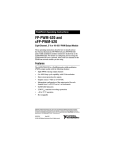
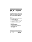
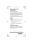
FieldPoint™ Operating Instructions
cFP-RLY-423
Four-Channel SPDT Relay Module
These operating instructions describe how to install and use the
National Instruments cFP-RLY-423. For more information about
configuring and accessing the cFP-RLY-423 over a network, refer
to the user manual for the FieldPoint network module you are
using.
Features
The cFP-RLY-423 is a Compact FieldPoint relay output module
with the following features:
•
Four single-pole double-throw (SPDT) relay channels
•
Switches up to 1.5 A at 35 VDC or 250 VAC
•
LED relay status indicators
•
Hot swappable
•
–40 to 60 °C operation
•
250 Vrms maximum isolation voltage
•
2,300 Vrms transient overvoltage protection
Installing the cFP-RLY-423
The cFP-RLY-423 mounts on a Compact FieldPoint backplane
(cFP-BP-x), which provides operating power to the module.
Installing the cFP-RLY-423 onto a powered backplane does not
disrupt the operation of the bank.
To install the cFP-RLY-423, refer to Figure 1 and complete the
following steps:
1. Align the captive screws on the cFP-RLY-423 with the holes
on the backplane. The alignment keys on the cFP-RLY-423
prevent backward insertion.
2. Press firmly to seat the cFP-RLY-423 on the backplane.
3. Using a number 2 Phillips screwdriver with a shank of at least
64 mm (2.5 in.) length, tighten the captive screws to 1.1 N ⋅ m
(10 lb ⋅ in.) of torque. The nylon coating on the screws prevents
them from loosening.
4
3
5
2
4
2
1
1 cFP I/O Module
2 Captive Screws
3 cFP Controller Module
4 Screw Holes
5 cFP Backplane
Figure 1. Installing the cFP-RLY-423
cFP-RLY-423
2
ni.com
Wiring the cFP-RLY-423
The cFP-CB-x connector block has connections for each of the four
cFP-RLY-423 relay channels and for an external supply to power
field devices. If you are using the cFP-RLY-423 in a hazardous
voltage application, you must use the cFP-CB-1 connector block
or a suitable hazardous voltage cable. A hazardous voltage is a
voltage greater than 42.4 Vpeak or 60 VDC.
Ensure that hazardous voltage wiring is
performed only by qualified personnel adhering to local
electrical standards.
Caution
Each relay channel of the cFP-RLY-423 has four terminals:
one NO (normally open), one NC (normally closed), and
two IC (isolated common).
Table 1 lists the terminal assignments for the signals of each
channel.
Table 1. Terminal Assignments
Terminal Numbers
Channel
NO
IC
NC
0
1
2,3
4
1
5
6,7
8
2
9
10,11
12
3
13
14,15
16
All of the COM terminals are connected internally and all of the
VSUP terminals are connected internally. NI does not recommend
using them with the cFP-RLY-423.
© National Instruments Corp.
3
cFP-RLY-423
Table 2. VSUP and COM Terminal Assignments
VSUP
COM
17
18
19
20
21
22
23
24
25
26
27
28
29
30
31
32
Cascading power between two modules defeats
isolation between those modules. Cascading power from
the network module defeats all isolation between
modules in the FieldPoint bank.
Caution
Connecting Loads to the cFP-RLY-423
Connect two loads and an external power supply to one channel
of the cFP-RLY-423 as shown in Figure 2. Install a 1.5 A, 250 V
maximum, fast-acting fuse suitable for the load at the connected
IC terminal to protect the module and the load from damage.
V
C
NO
Sourcing
Load
IC
1.5 A,
250 V max
IC
NC
+
or
–
AC
Sourcing
Load
VSUP
COM
cFP-RLY-423
Figure 2. Basic Field Connection
cFP-RLY-423
4
ni.com
The cFP-RLY-423 has four independent Form C electromechanical
relays. The relays are break-before-make. At power-up, all relays
are in the NC state. Turning the relay channel on breaks the NC–IC
connection and makes the NO–IC connection. Each relay can be
controlled independently, or all relays can change states
simultaneously.
There is an effective resistance of up to 200 mΩ between IC and
NC or NO. This resistance causes a voltage drop.1 For example, if
the current is 1.5 A, the voltage drop across the IC and NC or NO
terminals can be as high as 0.3 V.
The amount of current the relay can switch depends on the voltage,
the type of load, and the ambient temperature. Refer to the
Specifications section for more information.
Protecting Contacts from Inductive Loads
When inductive loads are connected to the relays, a large
counter-electromotive force can occur at relay switching time
because of the energy stored in the inductive load. These flyback
voltages can severely damage the relay contacts and greatly
shorten the life of the relay.
It is best to limit flyback voltages by installing a flyback diode
across an inductive DC load or a metal oxide varistor (MOV)
across an inductive AC load. Refer to the Guidelines for Selecting
Contact Protection Circuits section for more information.
In addition, the cFP-RLY-423 has internal protection MOVs to
prevent excessively high voltage from being applied across the
contacts. Each channel contains two MOVs: one between NC and
IC and one between NO and IC. However, National Instruments
recommends installing a protection circuit across any inductive
load, as close as possible to the load. The flyback protection MOVs
cause a small leakage current, which is detailed in the
Specifications section.
1
At the end of relay life, the path resistance rises rapidly above 1 Ω.
© National Instruments Corp.
5
cFP-RLY-423
Guidelines for Selecting Contact
Protection Circuits1
Proper selection is critical as the use of a contact-protection device
can extend contact life. When mounting the protection device,
always locate it near the immediate area of the load or contact.
Typically you should mount a protective device within 18 in. of
the load or contact.
Typical contact-protection circuits are shown here as an overview,
but you should thoroughly examine the circuit you are planning
to use.
Diode and Zener Diode Circuit
Diagram
Notes
Use in DC applications only.
Load
Use when diode circuit causes too long
release time.
Use zener diode with zener voltage about
equal to power supply voltage.
Diode Circuit
Diagram
Notes
Use in DC applications only.
Compared to RC type, circuit delays release
time (2 to 5 times values stated in catalog).
Load
For larger voltages, use diode with reverse
breakdown 10 times circuit voltage and
forward load circuit.
For smaller voltages, use reverse breakdown
voltage of 2 to 3 times power supply voltage.
1
This section has been reprinted with permission from American Zettler, Inc.
cFP-RLY-423
6
ni.com
CR (RC or Snubber) Circuits
Diagram
Notes
Circuit A is suitable for AC or
DC applications, but if used with
AC voltage, impedance of the load
should be smaller than that of the
CR circuit. Do not utilize for timer
loads, as leakage current can cause
faulty operations.
Load
Circuit B is suitable for AC or DC.
If the load is a relay or solenoid,
release times lengthen. Effective
when connected to both contacts,
power supply voltage across the
load is 100 to 200 V.
Load
Varistor Circuit
Diagram
Notes
Effective for AC and DC
applications.
Circuit slightly delays release time.
Effective when connected to both
contacts, power supply voltage
across the load is 100 to 200 V.
Load
In-Rush Current
The type of load and its in-rush current characteristics, together
with switching frequency, can cause contact welding. For loads
with in-rush current, measure the steady state current and in-rush
current to determine the proper relay. Some typical types of loads
and the in-rush current they create are summarized in Table 3.
Table 3. Typical Load Types and In-Rush Currents
Type of Load
In-Rush Current
Resistive load
Steady-state current
Motor load
5 to 10 times the steady-state current
Incandescent lamp load
10 to 15 times the steady-state current
© National Instruments Corp.
7
cFP-RLY-423
Table 3. Typical Load Types and In-Rush Currents (Continued)
Type of Load
In-Rush Current
Mercury lamp load
Approximately 3 times the steady-state
current
Sodium vapor lamp load
1 to 3 times the steady-state current
Capacitive load
20 to 40 times the steady-state current
Transformer load
5 to 15 times the steady-state current
Status Indicators
Figure 3 shows the status indicator LEDs on the cFP-RLY-423.
Figure 3. Status Indicators
After you insert the cFP-RLY-423 into a backplane and apply
power to the network module, the green POWER indicator lights
and the cFP-RLY-423 informs the network module of its presence.
When the network module recognizes the cFP-RLY-423, it sends
initial configuration information to the cFP-RLY-423. After the
cFP-RLY-423 receives this initial information, the green READY
indicator lights and the module is in normal operating mode.
In addition to the green POWER and READY indicators, each
channel has two green output state indicators labeled NO and NC.
These indicators show which terminal is connected to IC.
Isolation and Safety Guidelines
Read the following information before
attempting to connect the cFP-RLY-423 to any circuits
that may contain hazardous voltages.
Caution
This section describes the isolation of the cFP-RLY-423 and its
compliance with international safety standards. The field wiring
connections are isolated from the backplane. The isolation is
provided by the module, which has optical and galvanic isolation
barriers designed and tested to protect against transient fault
voltages of up to 2,300 Vrms. The cFP-RLY-423 provides double
insulation (compliant with IEC 61010-1) for working voltages of
cFP-RLY-423
8
ni.com
250 Vrms1. Safety standards (such as those published by UL
and IEC) require the use of double insulation between hazardous
voltages and any human-accessible parts or circuits.
Never try to use any isolation product between human-accessible
parts (such as DIN rails or monitoring stations) and circuits that
can be at hazardous potentials under normal conditions, unless the
product is specifically designed for such an application, as is the
cFP-RLY-423.
Even though the cFP-RLY-423 is designed to handle applications
with hazardous potentials, follow these guidelines to ensure a safe
total system:
•
The cFP-RLY-423 has a safety isolation barrier between the
I/O channels and the inter-module communication bus. There
is no isolation between channels unless otherwise noted. If any
of the channels on a module are wired at a hazardous potential,
make sure that all other devices or circuits connected to that
module are properly insulated from human contact.
•
Do not share the external supply voltages (the V and C
terminals) with other devices (including other FieldPoint
devices), unless those devices are isolated from human contact.
•
You must connect the protective earth (PE) ground terminal
on the cFP-BP-x backplane to the system safety ground. The
backplane PE ground terminal has the following symbol
stamped beside it: . Connect the backplane PE ground
terminal to the system safety ground using 14 AWG (1.6 mm)
wire with a ring lug. Use the 5/16 in. panhead screw shipped
with the backplane to secure the ring lug to the backplane
PE ground terminal.
•
As with any hazardous voltage wiring, make sure that all
wiring and connections meet applicable electrical codes
and commonsense practices. Mount backplanes in an area,
position, or cabinet that prevents accidental or unauthorized
access to wiring that carries hazardous voltages.
•
The isolation of the cFP-RLY-423 is certified as
double-insulated for working voltages of 250 Vrms. Do not use
the cFP-RLY-423 as the only isolating barrier between human
contact and working voltages of more than 250 Vrms.
1
Working voltage is defined as the signal voltage plus the common-mode voltage.
Common-mode voltage is the voltage of the module with respect to ground.
© National Instruments Corp.
9
cFP-RLY-423
•
Operate the cFP-RLY-423 only at or below Pollution Degree 2.
Pollution Degree 2 means that only nonconductive pollution
occurs in most cases. Occasionally, however, a temporary
conductivity caused by condensation must be expected.
•
Do not operate FieldPoint products in an explosive atmosphere
or where there may be flammable gases or fumes. If you need
to operate FieldPoint products in such an environment, the
FieldPoint products must be in a suitably rated enclosure.
•
Operate the cFP-RLY-423 at or below Installation Category II.
Installation Category II is for measurements performed on
circuits directly connected to the electrical distribution system.
This category refers to local-level distribution, such as that
provided by a standard wall outlet.
Specifications
The following specifications are typical for the range –40 to 60 °C
unless otherwise noted.
Relay Characteristics
Number of channels.......................... 4
Relay type ......................................... 1 Form C (SPDT),
nonlatching
Maximum switching capacity (resistive load)
20 mVAC to 250 VAC ................ 1.5 A at –40 to 45 °C
1.0 A at 45 to 55 °C
0.5 A at 55 to 60 °C
0 to 35 VDC ............................... 1.5 A at –40 to 45 °C
1.0 A at 45 to 55 °C
0.5 A at 55 to 60 °C
35 to 55 VDC ............................. 1 A at –40 to 55 °C
0.5 A at 55 to 60 °C
55 to 120 VDC ........................... 0.4 A
Minimum switching load.................. 100 mA at 5 VDC
DC path resistance
Initial .......................................... ≤200 mΩ
End of life................................... ≥1.0 Ω
cFP-RLY-423
10
ni.com
DC path resistance typically remains low for
the life of the relay. At the end of relay life, the path
resistance rises rapidly above 1 Ω. Load ratings apply
to relays used within the specification before the end of
relay life.
Note
Off-state leakage (120 VDC/250 VAC)
Frequency
Off-State Leakage
DC
0.12 µA
50/60 Hz
8 µA
Expected life
Mechanical ................................. 2 × 10⁷ operations min
Electrical..................................... 1 × 10⁵ operations at rated
resistive load
Maximum switching frequency
Mechanical ................................. 20 operations per second
Electrical..................................... 1 operation per second at
maximum load
Relay operate time ............................ <13 ms
Relay release time............................. <13 ms
Relay bounce time ............................ <6 ms
Contact material................................ Silver cadmium oxide
Physical
Indicators .......................................... Green POWER and
READY indicators,
8 green output state
indicators
Weight............................................... 142 g (5.0 oz)
Power Requirements
Power from network module ............ 1.2 W at 25 to 60 °C
1.5 W at –40 to 25 °C
© National Instruments Corp.
11
cFP-RLY-423
Isolation Voltage
Maximum isolation voltage .............. 250 Vrms,
Installation Category II
Channel-to-channel isolation ............ No isolation between
channels
Transient overvoltage........................ 2,300 Vrms
Environmental
FieldPoint modules are intended for indoor use only. For outdoor
use, they must be mounted inside a sealed enclosure.
Operating temperature ...................... –40 to 60 °C
Storage temperature .......................... –55 to 85 °C
Humidity ........................................... 10 to 85% RH,
noncondensing
Maximum altitude............................. 2,000 m; at higher altitudes
the isolation voltage ratings
must be lowered
Pollution Degree ............................... 2
Safety
This product is designed to meet the requirements of the following
standards of safety for electrical equipment for measurement,
control, and laboratory use:
•
IEC 61010-1, EN 61010-1
•
UL 3121-1, UL 61010C-1
•
CAN/CSA C22.2 No. 1010.1
For UL, hazardous location, and other safety certifications, refer to
the product label or to ni.com.
Electromagnetic Compatibility
CE, C-Tick, and FCC Part 15 (Class A) Compliant
Emissions.......................................... EN 55011 Class A at 10 m
FCC Part 15A above 1 GHz
Immunity........................................... EN 61326:1997 + A2:2001,
Table 1
Note For EMC compliance, you must operate this device
with shielded cabling.
cFP-RLY-423
12
ni.com
CE Compliance
This product meets the essential requirements of applicable
European Directives, as amended for CE marking, as follows:
Low-Voltage Directive (safety)......... 73/23/EEC
Electromagnetic Compatibility
Directive (EMC) ............................... 89/336/EEC
Refer to the Declaration of Conformity (DoC) for
this product for any additional regulatory compliance
information. To obtain the DoC for this product,
click Declarations of Conformity Information at
ni.com/hardref.nsf/.
Note
Where to Go for Support
For more information about setting up the FieldPoint system, refer
to these National Instruments documents:
•
FieldPoint network module user manual
•
Other FieldPoint I/O module operating instructions
•
FieldPoint connector block operating instructions
Go to ni.com/support for the most current manuals, examples,
and troubleshooting information.
For telephone support in the United States, create your service
request at ni.com/support and follow the calling instructions
or dial 512 795 8248. For telephone support outside the United
States, contact your local branch office:
Australia 1800 300 800, Austria 43 0 662 45 79 90 0,
Belgium 32 0 2 757 00 20, Brazil 55 11 3262 3599,
Canada (Calgary) 403 274 9391,
Canada (Montreal) 514 288 5722,
Canada (Ottawa) 613 233 5949, Canada (Québec) 514 694 8521,
Canada (Toronto) 905 785 0085,
Canada (Vancouver) 514 685 7530, China 86 21 6555 7838,
Czech Republic 420 2 2423 5774, Denmark 45 45 76 26 00,
Finland 385 0 9 725 725 11, France 33 0 1 48 14 24 24,
Germany 49 0 89 741 31 30, Greece 30 2 10 42 96 427,
India 91 80 51190000, Israel 972 0 3 6393737,
Italy 39 02 413091, Japan 81 3 5472 2970,
Korea 82 02 3451 3400, Malaysia 603 9131 0918,
Mexico 001 800 010 0793, Netherlands 31 0 348 433 466,
New Zealand 0800 553 322, Norway 47 0 66 90 76 60,
© National Instruments Corp.
13
cFP-RLY-423
Poland 48 0 22 3390 150, Portugal 351 210 311 210,
Russia 7 095 783 68 51, Singapore 65 6226 5886,
Slovenia 386 3 425 4200, South Africa 27 0 11 805 8197,
Spain 34 91 640 0085, Sweden 46 0 8 587 895 00,
Switzerland 41 56 200 51 51, Taiwan 886 2 2528 7227,
Thailand 662 992 7519, United Kingdom 44 0 1635 523545
cFP-RLY-423
14
ni.com
FieldPoint™, National Instruments™, NI™, and ni.com™ are trademarks of National Instruments Corporation.
Product and company names mentioned herein are trademarks or trade names of their respective companies.
For patents covering National Instruments products, refer to the appropriate location: Help»Patents in your software,
the patents.txt file on your CD, or ni.com/patents.
© 2003 National Instruments Corp. All rights reserved.
*323605B-01*
323605B-01
Jul03


![[c]FP-DO-401 Operating Instructions](http://vs1.manualzilla.com/store/data/005693758_1-4b10a2df6965457ee651014d1377996a-150x150.png)