1
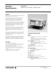
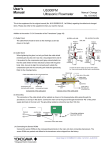
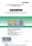
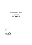
User’s Manual US300PM Ultrasonic Flowmeter Manual Change No. 15-009-E This is the supplement for the original manual (No. IM 01G05B02-01E, 1st Edition) regarding the added and changed items as below. Please also refer to this supplement when you read the manual. Addition to the chapter “2. Handling Precautions” (page 7) : Attention! The instrument must not be used in a corrosive atmosphere. Changes to the section “2.1 Scope of Delivery” (page 7) and the section “3.4.2 Rear Panel” (page 13): Change the figure of a nameplate to as below. Addition to the section “2.3 General Precautions” (page 8) : ・The power supply adapter and the AC cable are dedicated to US300PM. Please do not use them with other devices. ・Do not disassemble or remodel. Addition to the chapter “4. Getting Started” (page 15) : Attention! The current outputs may temporarily turn unstable during the switch-on sequence and parameter display / setting mode. Take care of your process not to be affected by this behavior. Manual Change for IM 01G05B02-01E 1st Edition : No.15-009-E July.30 2015-00 Addition to the section “4.2.1 Key Operations” (page 16) and related pages : Refer to the following table for the function of corresponding key operations. The correct explanations for these key operations in the related pages are also as the table below. Related pages: BRK “16.2 US300PM doesn’t react anymore” (page 113) ENTER INIT [Operation during the measurement or menu display] RESET: Press these three keys simultaneously to recover from an error. This has RESET the same effect as restarting the unit. Data will not be affected. INIT (cold start): Press these three keys simultaneously and release ENTER first. After acknowledging the display of main menu, release (i) BRK key first and then (ii) C key. This will initialize the instrument. Most parameters and settings are reset to the factory default values. The memory will not be cleared. Note that when the data logging function is activated, the DELETE MEAS.VAL. display will appear instead of main menu. In this case, after releasing (i) BRK key first and then (ii) C key, select NO or YES and then press ENTER to finish the procedure. ON BRK INIT [Operation when powering the instrument on] INIT (coldstart): Pressing these two keys simultaneously and after acknowledging the display of main menu, release (i) BRK first and then (ii) C. This will initialize the instrument. Most parameters and settings are reset to the factory default values. The same procedure is required as above when the DELETE MEAS.VAL. display appears. Addition to the section “5.6 Selection of the Sound Path Factor” (page 30) : When you select “auto” for “Sound Path” described at the section “11.2 Settings for Dialogues and Menus”, the setting for the sound path factor will be automatic. In this case, “Reflection Mod” display will appear and you can select either “Diagonal Mode” by “no” or “Reflection Mode” by “yes”. A:Reflection Mod no >YES< When the pipe outer diameter is more than 600mm, the sound path factor as “1” (one) is recommended. Otherwise, the measurement may become unstable when flow velocity or fluid temperature changed. Addition to the section “5.7.2 Mounting of the Transducers” (page 31) : The pipe wall thickness may slightly vary from part to part. Check it in advance by applying a wall thickness probe or some other ways and avoid mounting the transducers on such parts. Addition to the section “5.7.2.4 Mounting with Fixtures” (page 32) : Attention! When using mounting fixtures, there may arise some air gap between the transducer surface and pipe wall because of any distortion of the pipe wall. Make sure to avoid having such air gap between them. Manual Change for IM 01G05B02-01E 1st Edition : No.15-009-E July.30 2015-00 Addition to the section “6.1 Selection of the Physical Quantity and of the Unit of Measurement” (page 37) : Attention! In case of mass flow, select “Other Medium” as a measured fluid. When “Other Medium” has been selected, US300PM requests to enter the density which is used to calculate mass flow. Changes to the section “7.2 Flow Totalizers” (page 41) : Two of the key operations have been changed as below. OON To reset the two flow totalizers to zero: Press key To deactivate flow totalizing: Press key three times when a totalizer is displayed. OOFF three times when a totalizer is displayed. Addition to the section “11.2 Settings for Dialogues and Menus” (page 72) : “Sound Path” setting appears next to “Meas.Point No.” and you can select “auto” or “user”. When you select “auto”, the setting for the sound path factor will be automatic. Sound Path auto >USER< Changes to the section “11.6 Charging the Battery” (page 77) : Change “The chargeable NiCd-batteries guarantee an operating time of approximately 14 hours.” to “The chargeable NiCd-batteries guarantee an operating time of approximately 10 hours at room temperature (20°C / 68°F), with full charge.” Addition to the section “15.5 Activation of a Pulse Output” (page 101) : Maximum pulse output rate is 2 pulse per second (+/-20%). Set the “Pulse Value” and the “Pulse Width” so that the actual maximum flow in the pipe is less than half the displayed value (“Max – Value”). Example: 3 The actual maximum flow 120m /h Pulse Value = 0.02m 3 Pulse Width = 150ms INFO: Max – Value 3 240.0m /h Attention! OON It is necessary to activate flow totalizers by pressing key to get the actual pulse output. Refer to the section 7.2 for flow totalizers. Changes to the chapter “A Standard Specification” (page 117 to 124) : Please use the following sheets for this chapter. Manual Change for IM 01G05B02-01E 1st Edition : No.15-009-E July.30 2015-00 Standard Specifications A Standard Specifications US300PM General Fluid: Liquid (Turbidity < 10,000 mg/L, Sound velocity 800 to 3,500 m/s, Temperature –30 to +200°C / –22 to +392°F) Measured Quantities: Volume flow, mass flow (by setting density), flow velocity, sound velocity in the fluid Wall thickness of the pipe (available when optional wall thickness probe is provided) Current Output: None (standard), one, or two (optional) Range 4 to 20 mA (Load resistance 0 to 500 Ω) Note: The current outputs may temporarily turn unstable during the switch-on sequence and parameter display / setting mode. Take care of your process not to be affected by this behavior. Measuring Principal: Transit time method using ultrasonic signal Frequency Output: None (standard), or one (optional) Range 0 to 1 kHz Contact type: Open-collector, 24 V / 4 mA Pipe Sizes: 25 to 6,500 mm (1 to 255 inches) (covered by three types of transducers) Binary Output: None (standard), one, or two (optional) Contact type: Open-collector, 24 V / 4 mA Pipe and Lining Materials: Carbon steel, Stainless steel, Grey cast iron, Ductile iron, Copper, Glass, PVC, etc Input / Output Terminal Configuration: Round socket connectors for flow and wall-thickness measuring inputs on the front panel. Banana plug jacks (+,–) for current, frequency, and binary outputs in the rear panel. Flow Velocity Range: ±0.01 to ±25 m/s (±0.033 to ±82 ft/s) Resolution: 0.025 cm/s (0.01 in/s) Repeatability: 0.15% of reading ±0.01 m/s (0.033 ft/s) Accuracy: (Note) Under fully developed rotationally symmetrical flow profile Volumetric flow: ±1 to 3% of reading ±0.01 m/s (0.033 ft/s) depending on pipe geometry and accuracy of entered pipe dimensions. Flow velocity: ±0.5% of reading ±0.01 m/s (0.033 ft/s) over sonic path LCD Display: 2 line x 16 character LCD display with backlight that can be switched on/off. Configurable to display two measured values (e.g., flow rate and total flow) simultaneously, or to display values from dual input channels alternately. LED Lamp: SIGNAL Lamp (green/red): Indicates input signal status with green/red light, equipped for each channel. BATTERY Lamp (red): Indicates battery charging status with red light. Measuring Cycle: 100 to 1000 Hz (per one channel) Keyboard: 15 keys (numerical, functional, or both) including four arrow-shaped keys for cursor operation, enabling easy access through its interactive menu structure. Straight Pipe Run in the Upstream: 10 to 50 pipe diameters, depending on the kind of flow disturbances Display Language: Czech, Danish, Dutch, English (default), French, German, Norwegian, Polish, Turkey Ultrasonic Flowmeter, Main Unit Housing Material: Aluminum Painting: Powder coating Dust and Water-proof: IP54 (EN60529) Measuring Input (flow / wall-thickness): Two as standard (Channel A, Channel B). Both flow transducers and a wall thickness probe can be connected freely to whichever channel. IM 01G05B02-01E 1st Edition Flow Measurement: Flow velocity, Volume flow, Mass flow Sound Velocity / Signal Amplitude Measurement (Online): Sound velocity and signal amplitude in the fluid available on-line simultaneously with flow measurement. Totalization Function: Totalizes the volume flow or mass flow. Ten-digit number for both forward/reverse directions of each channel. Damping Function: Time constant 0 to 100 seconds, moving average. 1 Standard Specifications Sound Velocity Measurement (Off-line): Measures the sound velocity of unknown fluid starting from its estimated sound velocity. The result can be transferred to the current fluid parameter. Wall Thickness Measurement (Off-line): Measures the wall thickness of unknown pipe (materialknown) using optional wall thickness probe. The result can be transferred to the current pipe parameter. Arithmetic Operation on Dual-Channel / Dual-Path Inputs: Arithmetic operations get the outcomes for calculation channel Y and Z by taking sum, average, or difference of two flow values from input channel A and B. Taking absolute values of each input independently in the calculation is also possible. Note: Two sets of transducers are necessary. Pulse Output (optional): Available via optional binary outputs. Pulse value: 0.01 to 1000 of totalization unit Pulse width: 100 to 1000 ms (±20%) Maximum output rate: 2pps (pulse/second) ±20% Alarm Output (optional): Available via optional binary outputs where each alarm item is assigned one-to-one. Alarm properties are also selectable for each alarm one-by-one. Alarm items: High limit, Low limit, Flow direction change, Quantity limit (for batch operation), and Error (measurement impossible) Alarm properties: Normal open / Normal close, Nonhold / Hold (at the alarm detection) Output Signal Configuration: Freely configurable including independent dual flow value outputs. Current / frequency outputs: Flow velocity, Volume flow, Mass flow, Sound velocity, or Signal amplitude Binary outputs: Pulse or Alarm Data Logging Function: Data storage capacity of 27,000 values (standard) or 100,000 values (optional). Storage rate is selectable from 1 s, 10 s, 1 min, 10 min, 30 min, 1 h, or any other rate between 1 s to 43200 s (12 h) by the second. For each period of measurement, stored values are grouped by a user-defined measuring point name. Stored values can be transferred to a personal computer via RS232 serial communication port. Communication Function: Transfers the measured values to a personal computer or a serial printer. Both on-line/off-line transfer during/after the measurement available. Output item: Flow value (flow velocity, volume flow, or mass flow), Totalization (forward, reverse), Sound velocity, Signal amplitude Output format setting: Spacing (for printer), Decimal point character, Data delimiter Communication interface: RS232 Communication port: D-sub 9-pin, male 2 Time-Programmable Measurement Function: Automatic start / stop of the measurement without human operation using internal clock for specific systems. Can be used with current output, binary output, data logging function, and/or communication function for recording the measurement. Site Parameters Storage Function: Eliminates the necessity of re-entering parameters for additional measurement on a site. Totally 80 sets of site parameters for pipe/fluid settings are available with user-defined site names. Additionally, 14 sets of separate site parameters for not only pipe/fluid but also output-options setting in sets available. Material / Fluid List Customization Function: The lists of material / fluid in the parameter menu are editable. Unnecessary items can be cut off from the menu for user’s convenience. Registration of new material / fluid data is also possible totally up to 13 items with user-defined names. Power Supply: Power supply system: Built-in rechargeable battery (6V/4Ah) Power supply adapter (Input: 100 to 240VAC, 50/60 Hz, works also as battery charger) Battery operating time (with full charge): Maximum around 10 hour continuous measurement at room temperature (20°C / 68°F) Power consumption: Less than 15W Safety and EMC Standard: General safety: EN61010-1:2010 EN61010-2-030:2010 Altitude at installation site: Max. 2000 m above sea level Overvoltage category: Overvoltage category II Pollution degree: Pollution degree 2 EMC regulation: EN61326-1:2006 Operating Conditions: Ambient temperature: –10 to +60°C (14 to 140°F) Ambient humidity: 0 to 95% RH or less (Non-condensation) (Note) Lengthy operation at 80% or more is not recommended. Transducers Basic Construction: A set of transducers are composed of a pair of sensor elements (often called just as “transducers”), and transducer cables with a connector at one end, which is to be inserted into the measuring input sockets in the front panel of US300PM main unit. The transducer cables are armed with stainless steel flexible tube. (Note) Fixing hardware (mounting fixtures, chains) and acoustic couplant are usually included in a set of transduces, specified in its model code by their kinds or with/without. Material: Case of sensor elements: Stainless steel EN/DIN 1.4571 (JIS SUS 316Ti, AISI 316Ti SS equivalent) Sensing surface of sensor elements: General temperature type: PEEK (Poly Ether Ether Keton) High temperature type: Polyimid IM 01G05B02-01E 1st Edition Standard Specifications Dust and Water-proof: General type: IP65 (EN60529) Immersible type: IP67 (EN60529) Applicable Pipe Sizes (inner diameter): Medium type: 25 to 400 mm (1 to 16 inches) Lager type: 100 to 2,500 mm (4 to 98 inches) Very large type: 2,000 to 6,500 mm (78 to 255 inches) (Note) Only “6,500 mm” above is the size for outer diameter. Fluid Temperature Range: General temperature type: –30 to +130°C (–22 to +266°F) High temperature type: –30 to +200°C (–22 to +392°F) Note: Pay attention also to temperature specification of the couplant you choose. Mounting Fixture Variety and Usage: Retaining clip: Inserted into the groove on the upper side of transducers. Transducers are fixed onto the pipe by fixing chains hooked at the retaining clip. Mounting fixture standard type: Consisted of two metal blocks with a slide-in ruler to hold transducers in place and adjust their distance easily. Transducers are fixed onto the pipe by fixing chains hooked at the mounting fixture. Mounting fixture magnetic type: Pieces of magnet are attached onto both sides of blocks for the “standard type” above. When the pipe material is what magnet pulls, transducers are fixed onto the pipe by magnetic power eliminating the use of fixing chains. If necessary, magnet pieces can be easily added for stronger magnetic power. Optional Extension Cable Extends the length of transducer cable when the standard length is not enough for the site conditions. Select the extension length from 5 m (16 ft), 10 m (32 ft), or 20 m (65 ft). Wall Thickness Probe Specified in the option code of US300PM main unit. Model codes as accessories also available for separate/additional orders (listed later). Fluid Temperature Range: General temperature type: –20 to +60°C (–4 to +140 °F) High temperature type: 0 to +200°C (32 to 392°F) Measuring Performance: Measuring range: 1.0 to 200 mm (0.04 to 7.8 inches), depends on the material Resolution: 0.01 mm (0.0004 inch) Accessories Standard Accessories for US300PM Main Unit: Transportation case, Measuring tape, and Built-in battery set always come with US300PM. Fixing Hardware, Couplant, etc: Specified in the suffix code of US300FT transducers. Model codes as accessories also available for separate/additional orders (listed later). IM 01G05B02-01E 1st Edition Power Supply Adapter and AC cable: The power supply adapter and the AC cable are dedicated to US300PM. Please do not use them with other devices. Data Transfer Software General: The software installed on a personal computer receives one or more records of logging data and parameter sets stored in US300PM main unit via RS232 communication port. Data can be viewed or graphed on a PC monitor, or exported as a text file. This software works while US300PM is off-line (not measuring flow) where current output goes down to zero. Function: Displaying Parameter Record: Display parameter record of selected measuring data set. Displaying Measured Data in Table: Display measured data of selected measuring data set in table format. Displaying Data in Graph: Display measured data of selected measuring data set in graphic format. Marker type and color for each line of values selectable. Scales for time-axis and value-axis can be changed from default condition of automatic scaling. Graph printing function embedded. Displaying Statistical Data: Display statistical data of the measurement. Total data points, minimum, maximum, average and standard deviation of the measured data can be shown. Data range for statistical processing can be designated if necessary. Exporting Text File: Parameter record and measured data can be exported to a text file. Options for exporting items or their formats are available. Entering Remarks: User’s remarks for each measured data can be entered and edited in the transferred data file on a personal computer. Remarks can be displayed in the main window of the software. Display Language: English, German (Note) Help is available only in English. Operating Environment: Personal Computer: Microsoft® Windows® hardware compatible, one or more RS232 port Operating System: Microsoft® Windows® 98, ME, NT, 2000, XP Standard Accessories: RS232 cable, RS232 adapter 9/25 * Microsoft® and Windows® are registered trademarks of Microsoft Corporation in the United States and/or other countries. 3 Standard Specifications Units of Measurement Volume flow Flow velocity Mass flow Totalizers Volume Mass m3/h m/s g/s m3 g m3/min inch/s t/h l kg m3/s kg/h gal t l/h kg/min Sound velocity m/s l/min l/s USgph USgpm USgps bbl/d bbl/h bbl/m 1 gallon [US] = 3.78 l; 1 barrel = 42 gallons = 158.76 l 4 IM 01G05B02-01E 1st Edition Standard Specifications Model and Suffix Code Ultrasonic flowmeter, portable type Model US300PM Suffix code ····························· -A0 ······················ -A1 ······················ Output -A2 ······················ 1 ··················· Power Supply Adapter and AC 2 ··················· cable 3 ··················· 4 ··················· 5 ··················· 6 ··················· -2 ··············· -N ·········· /PU1 ···· Option Transducers for portable type (*2) Specification Ultrasonic flowmeter, portable type No current output One current output Two current outputs Japan USA Europe United Kingdom Australia South Africa Always 2 Always N One binary (pulse or alarm) output (open-collector) (*1) /PU2 ···· Two binary (pulse or alarm) outputs (open-collector) (*1) /FQ1 ···· Frequency output (opencollector, 0 to 1kHz) /DLX ···· Data logging extension (100,000 values) /BGT ···· Tag number on nameplate (in the nameplate label, maximum 16 characters) /WTG ··· Wall thickness probe for general temperature (–20 to +60°C / –4 to +140°F) /WTH ··· Wall thickness probe for high temperature (0 to +200°C / 32 to 392°F) *1: Option /PU1 and /PU2 are exclusive. Optional extension cable for portable type Model Suffix code Specification US300PC ···················· Optional extension cable for portable type -A005 ·········· Cable length 5 m (16 ft) Length -A010 ·········· Cable length 10 m (32 ft) -A020 ·········· Cable length 20 m (65 ft) Data transfer software Model Suffix code Specification US300SA ···················· Data transfer software (Windows version) Including connecting kit (RS232 cable for connection, RS232 adapter 9/25) Language -1 ················ English / German version 00 ···· Always 00 IM 01G05B02-01E 1st Edition Model US300PT Usage Suffix code Specification ······························ Transducers for portable type -G ························· General purpose (IP65) -W ························ Immersible (IP67) BG ····················· Medium & General Pipe Size / (with 3 m / 9.8 ft cable) Fluid Temperature BH ····················· Medium & High (with 3 m / (*3) 9.8 ft cable) CG ····················· Large & General (with 4.4 m / 14.4 ft cable) CH ····················· Large & High (with 4.4 m / 14.4 ft cable) DG ····················· Very large & General (with 12 m / 39.4 ft cable) Mounting fixture -C ··················· Retaining clip type (set of (*4) two clips) -S ··················· Standard type (set of two blocks, including ruler marked length 330 mm, equivalent to 13 in.) -M ··················· Magnetic type for general temp. (–30 to +100°C / –22 to +212°F, set of two blocks, including ruler marked length 330 mm, equivalent to 13 in.) -N ··················· None Fixing chain (*4) B ················· For 25 to 1200 mm (1 to 47 in.) Fixing chains of 2 m / 6.5 ft length (2 x 2) C ················· For 1200 to 3000 mm (47 to 118 in.) Fixing chains of 2 m / 6.5 ft length (5 x 2) D ················· For 3000 to 6500 mm (118 to 255 in.) Fixing chains of 2m / 6.5 ft length (11 x 2) N ················· None G ·············· General temperature type (– Acoustic couplant 30 to +130°C / –22 to +266°F) H ·············· High temperature type (–30 to +200°C / -22 to +392°F) Option N ·············· None /TTP ······ Transducer tag plate (maximum 16 characters) *2: Two sets of transducers are necessary when applying dual channel/path measurement. *3: The alphabetic characters in the suffix code represent pipe sizes and fluid temperature ranges are below. B: Medium type (25 to 400 mm / 1 to 16 in.) C: Large type (100 to 2,500 mm / 4 to 98 in.) D: Very large type (2,000 to 6,500 mm / 78 to 255 in.) G: General temperature (–30 to +130°C / –22 to +266°F) H: High temperature (–30 to +200°C / –22 to +392°F) *4: When selecting code –C or –S for mounting fixture, always select code B, C, or D for fixing chain. When selecting code –M for mounting fixture, fixing chains are optional. When selecting code –N for mounting fixture, select also code N for fixing chain. 5 Standard Specifications Accessories (for ultrasonic flowmeter US300PM) Model Description USPA301 Wall thickness probe for general temperature (–20 to +60°C / –4 to +140°F) USPA302 Wall thickness probe for high temperature (0 to +200°C / 32 to 392°F) USPA311 Power supply adapter (100 to 240 V AC input) USPA321 AC cable (Japan) USPA322 AC cable (USA) USPA323 AC cable (Europe) USPA324 AC cable (United Kingdom) USPA325 AC cable (Australia) USPA326 AC cable (South Africa) USPA331 Battery set (6 V 4Ah) (*5) USPA341 Transportation case (*5) *5: Always comes with US300PM. Accessories (others) Model Description USPA401 RS232 cable (*6) USPA402 RS232 adapter 9/25 (*6) USPA411 Measuring tape (*7) *6: Included in data transfer software US300SA as standard. *7: Included in US300PM as standard. 6 Accessories (for transducers US300PT) Model Description USPA001 Fixing strap (10 m / 32 ft length) USPA002 Fixing strap (20 m / 65 ft length) USPA011 Fixing clips (medium type, for pipe size 40 to 100 mm / 1.5 to 4 in., set of two clips) USPA012 Fixing clips (large type, for pipe size 100 to 6500 mm / 4 to 255 in., set of two clips) USPA021 Fixing bands (only for pipe size 25 to 50 mm / 1 to 2 in.) USPA032 Fixing chains (set of two extensible chains) (2 m / 6.5 ft length, equal to 600 mm / 23 in. diameter) USPA033 Repair set for fixing chains USPA034 Retaining clips (set of two clips, used with fixing chains) USPA036 Fixing chains (set of two extensible chains) (0.5m / 1.6 ft length, equal to 150mm / 5.9 in. diameter) USPA037 Fixing chains (set of two extensible chains) (1 m / 3.2 ft length, equal to 300 mm / 11.8 in. diameter) USPA053 Mounting fixture short ruler type (for transducers medium pipe size type, temperature range –30 to +200°C / –22 to +392°F, set of two blocks with 120 mm / 4.7 in. ruler) USPA054 Mounting fixture standard type (for transducers medium pipe size type, temperature range –30 to +200°C / –22 to +392°F, set of two blocks with 330 mm / 13 in. ruler) USPA055 Mounting fixture magnetic general temperature type (for transducers medium pipe size type, temperature range –30 to +100°C / –22 to +212°F, set of two blocks with 330 mm / 13 in. ruler) USPA057 Mounting fixture standard type (for transducers large or very large pipe size type, temperature range –30 to +200°C / –22 to +392°F, set of two blocks with 330 mm / 13 in. ruler) USPA058 Mounting fixture magnetic general temperature type (for transducers large or very large pipe size type, temperature range –30 to +100°C / – 22 to +212°F, set of two blocks with 330 mm / 13 in. ruler) USPA073 Additional magnets for mounting fixture magnetic general temperature type (for transducers medium pipe size type, temperature range –30 to +100°C / –22 to +212°F, set of two magnets) USPA075 Additional magnets for mounting fixture magnetic general temperature type (for transducers large or very large pipe size type, temperature range –30 to +100°C / –22 to +212°F, set of two magnets) USPA081 Ruler for mounting fixture (marked length 120 mm, equivalent to 4.7 in.) USPA082 Ruler for mounting fixture (marked length 330 mm, equivalent to 13 in.) USPA091 Acoustic couplant general temperature type (100 g, –30 to +130°C) (0.22 lb, –22 to +266°F) USPA092 Acoustic couplant high temperature type (100 g, –30 to +200°C) (0.22 lb, –22 to +392°F) IM 01G05B02-01E 1st Edition Standard Specifications Dimensional Drawings Unit: mm (inch) Ultrasonic flowmeter US300PM Transducers US300PT-□B□ Transducers US300PT-□C□, US300PT-□D□ Length / Weight Transducer X m (inch) Y m (inch) □ □ US300PT-□C□ US300PT-□D□ 2.0 ( 78.7) 1.0 ( 39.4) 3.0 (118.1) 0.6 (1.32) 2.0 ( 78.7) 2.4 ( 94.5) 4.4 (173.2) 1.2 (2.65) 5.0 (196.9) 7.0 (275.6) 12.0 (472.4) 2.2 (4.85) US300PT- B X+Y m (inch) Weight kg (lb) Optional extension cable US300PC-A□□□ Length / Weight Optional extension cable US300PC-A005 US300PC-A010 US300PC-A020 IM 01G05B02-01E 1st Edition L m (inch) 5.0 (196.9) 10.0 (393.7) 20.0 (787.4) Weight kg (lb) 0.4 (0.88) 0.6 (1.32) 1.6 (3.53) 7 Standard Specifications Wall thickness probe for general temperature (–20 to +60°C / –4 to +140°F) (option /WTG or model USPA301) Unit: mm (inch) Wall thickness probe for high temperature (0 to +200°C / 32 to 392°F) (option /WTH or model USPA302) Length / Weight Wall thickness probe /WTG or USPA301 /WTH or USPA302 8 L m (inch) 1.5 (59.1) 1.5 (59.1) Weight kg (lb) 0.17 (0.37) 0.24 (0.53) IM 01G05B02-01E 1st Edition