1
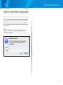
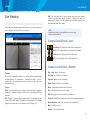
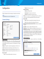
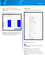
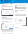
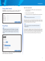
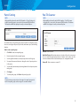
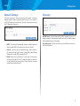
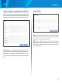
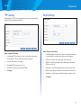
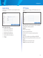
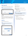
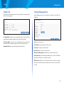
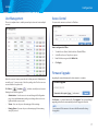
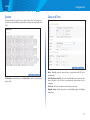
User Guide
Linksys SMB-Series Cameras
LCAD03FLN
LCAD03VLNOD
LCAB03VLNOD
LCAM0336OD
Linksys
Table of Contents
Table of Contents
HOW TO ACCESS WEB CONFIGURATION . . . . . . . . . . . . . . 1
LIVE VIEWING . . . . . . . . . . . . . . . . . . . . . . . . . . . . . . . . 2
CONFIGURATION . . . . . . . . . . . . . . . . . . . . . . . . . . . . . . 4
Camera Settings . . . . . . . . . . . . . . . . . . . . . . . . . . . . . . . 4
Video Settings . . . . . . . . . . . . . . . . . . . . . . . . . . . . . . . . 5
Audio Settings . . . . . . . . . . . . . . . . . . . . . . . . . . . . . . . . 6
Privacy Mask Control . . . . . . . . . . . . . . . . . . . . . . . . . . . . 7
Preset Point . . . . . . . . . . . . . . . . . . . . . . . . . . . . . . . . . . 7
Patrol Setting . . . . . . . . . . . . . . . . . . . . . . . . . . . . . . . . . 8
Pan-Tilt Scanner . . . . . . . . . . . . . . . . . . . . . . . . . . . . . . . 8
Network Settings . . . . . . . . . . . . . . . . . . . . . . . . . . . . . . 9
Discovery . . . . . . . . . . . . . . . . . . . . . . . . . . . . . . . . . . . 9
DDNS (dynamic domain name service . . . . . . . . . . . . . . . . 10
HTTP/HTTPS . . . . . . . . . . . . . . . . . . . . . . . . . . . . . . . . 10
Multicast . . . . . . . . . . . . . . . . . . . . . . . . . . . . . . . . . . 11
QoS . . . . . . . . . . . . . . . . . . . . . . . . . . . . . . . . . . . . . . 11
Event Settings . . . . . . . . . . . . . . . . . . . . . . . . . . . . . . . 11
Motion Detection . . . . . . . . . . . . . . . . . . . . . . . . . . . . . 12
Digital Input . . . . . . . . . . . . . . . . . . . . . . . . . . . . . . . . 12
Audio Detection . . . . . . . . . . . . . . . . . . . . . . . . . . . . . . 12
FTP Settings . . . . . . . . . . . . . . . . . . . . . . . . . . . . . . . . 13
Email Settings . . . . . . . . . . . . . . . . . . . . . . . . . . . . . . . 13
Samba Settings . . . . . . . . . . . . . . . . . . . . . . . . . . . . . . 14
HTTP Settings . . . . . . . . . . . . . . . . . . . . . . . . . . . . . . . 14
Digital Output (DO) . . . . . . . . . . . . . . . . . . . . . . . . . . . . 15
Audio Clip . . . . . . . . . . . . . . . . . . . . . . . . . . . . . . . . . . 15
Video Clip . . . . . . . . . . . . . . . . . . . . . . . . . . . . . . . . . . 16
Storage Management . . . . . . . . . . . . . . . . . . . . . . . . . . 16
User Management . . . . . . . . . . . . . . . . . . . . . . . . . . . . 17
Access Control . . . . . . . . . . . . . . . . . . . . . . . . . . . . . . . 17
Firmware Upgrade . . . . . . . . . . . . . . . . . . . . . . . . . . . . 17
Back Up and Restore . . . . . . . . . . . . . . . . . . . . . . . . . . . 18
Reset to Default . . . . . . . . . . . . . . . . . . . . . . . . . . . . . . 18
Reboot . . . . . . . . . . . . . . . . . . . . . . . . . . . . . . . . . . . . 18
System . . . . . . . . . . . . . . . . . . . . . . . . . . . . . . . . . . . . 19
Date and Time . . . . . . . . . . . . . . . . . . . . . . . . . . . . . . . 19
Save File Folder . . . . . . . . . . . . . . . . . . . . . . . . . . . . . . 20
LED Indicators . . . . . . . . . . . . . . . . . . . . . . . . . . . . . . . 20
Device Information . . . . . . . . . . . . . . . . . . . . . . . . . . . . 20
VMS Compatibility . . . . . . . . . . . . . . . . . . . . . . . . . . . . 21
SPECIFICATIONS . . . . . . . . . . . . . . . . . . . . . . . . . . . . . 22
Model No.: LCAD03FLN . . . . . . . . . . . . . . . . . . . . . . . . . 22
Model No.: LCAD03VLNOD . . . . . . . . . . . . . . . . . . . . . . . 23
Model No.: LCAB03VLNOD . . . . . . . . . . . . . . . . . . . . . . . 24
Model No.: LCAB03VLNOD . . . . . . . . . . . . . . . . . . . . . . . 25
ii
Linksys
How to Access Web Configuration
How to Access Web Configuration
To access the camera’s live view, open a Web browser and enter the IP address
of the camera. The login window will pop up requesting a user name and
password. The default user name and password are “admin” and “admin.” For
accounts other than the administrator’s account, remember the password for
future convenience.
NOTE:
If you don’t have a DHCP server in the network, the default Camera
IP address is 192.168.1.254.
1
Linksys
Live Viewing
Live Viewing is the default page that opens when you access the camera. Live
video is displayed directly in the browser window.
Live Viewing
UDP - This protocol allows for more real-time audio and video streams.
However, network packets may be lost due to network burst traffic and
images may be broken. The UDP connection time-sensitive responses are
more important than video quality.
NOTE:
Camera Control Panel is only available when you are using
Windows Internet Explorer.
Camera Control Panel - Icons
Physical Details
Channels
The network camera offers simultaneous dual stream for optimized quality
and bandwidth. Go to Configuration → Camera/Video/Audio → Video to
configure the codec compression and video resolution or refer to the video
configuration page.
/
Recording on/off - displays the status of the recording video.
/
MIC on /off - displays the status of the microphone volume.
/
Speaker on/off - displays the status of the speaker.
/
MD on/off - displays the status of Motion Detection.
Camera Control Panel - Buttons
Play or Stop - play or stop the video.
Recording - record video to a computer.
Snapshot - capture and save still images.
Digital Zoom - enable the zoom operation.
Protocol
Mirror - horizontally reflect the live video display.
HTTP - This unicast method can be used to traverse firewalls. Firewalls are
commonly configured to allow the HTTP protocol, thus allowing RTP to be
tunneled.
Flip - vertically reflect the live video display.
TCP - This protocol guarantees the complete delivery of streaming data and
provides better video quality. The downside of using this protocol is that the
quality of its real-time effect is less than that of the UDP protocol.
Full Screen - enable full screen mode; press the Esc key to return to normal mode.
Real Size - toggle between real size and normal mode.
Motion Detection - enable the motion detection alert function.
Mute - turn off the sound.
Default - restore default settings.
2
Linksys
Live Viewing
Talk - transmit audio through the camera using the computer microphone.
Brightness - Drag the slider bar to adjust the image brightness level.
Mic Volume - Drag the slider bar to adjust the volume of the camera microphone.
Speaker Volume - Drag the slider bar to adjust the camera speaker volume.
3
Linksys
Configuration
Configuration
Manual - Control exposure yourself.
Advanced AE Setting
Flicker-Free - Eliminates flicker.
Click the Configuration tab on the main page to change the camera settings.
NOTE:
Only administrators can access the Configuration tab.
Camera Settings
Environment - Select outdoor or indoor mode.
AE Speed - Automatically control exposure speed.
De-Noise - Set on range from 1 to 3, with 3 giving the best video resolution. Set
to auto to have camera automatically filter the frame-to-frame defects.
Mirror and Flip
Mirror - Enable to horizontally reflect the display of the live video.
Flip - Enable to vertically reflect the display of the live video.
IR Cut (Only available with models with a IR-Cut) - Deactivate or activate the
IR cut filter.
Color Effect - Select color or black-and-white video streams.
White Balance - Adjusts for different types of lighting to capture accurate colors.
WDR (Wide Dynamic Range) - In a scene with extremely bright and dark areas
or in backlit situations where a person is in front of a bright window, a typical
camera would produce an image where objects in the dark areas would hardly
be visible. Wide dynamic range solves this by applying techniques such as
using different exposures for different objects in a scene to enable objects in
both bright and dark areas to be visible.
Profile Management
Camera Settings
Profile - Up to five profiles can be created for different lighting environments.
Day and night are default profiles. You can create up to three additional profiles.
Select a profile from the drop-down menu or select different icons to change
profile settings.
You can schedule profiles to change at specific times, or when lighting
conditions change.
Brightness - Drag the bar to adjust the image brightness level from -5 to +5.
Contrast - Drag the bar to adjust the image contrast level from -5 to +5.
Sharpness - Drag the bar to adjust the image sharpness level from -5 to +5.
Saturation - Drag the bar to adjust the image saturation level from -5 to +5.
Exposure Control
Auto - The camera will automatically control exposure.
4
Linksys
Always - Use a single profile selected from the drop-down menu.
Day & Night - Schedule separate profiles for day and night. Select profiles from
the drop-down menus.
Configuration
Video Settings
The network camera offers two separate streams for different viewing options.
Schedule - Schedule specific time periods for different profiles.
Digital Inputs (Only available with models with a DI/DO) - Profiles will be
managed by an external sensor. Select profiles from the drop down menu.
Profiles will change according to different trigger voltage levels.
Wide Angle View - Captures a greater view angle.
Stream
Video Codec - Three choices of video codec standards for real-time viewing:
H.264, MPEG-4 and MJPEG.
Video Resolution - Choose the best resolution recording settings.
Frame Rate - Set a higher frame rate for smoother video quality.
Bitrate Mode - Select Variable Bitrate to manually configure the bitrate. Select
Constant Mode to have the bitrate set by the video codec. Set the bitrate higher
for better quality
5
Linksys
Configuration
Quality - Video quality can be set in the range from Level 1 to Level 6, with
Level 6 producing the best image quality.
If DIGEST authentication is selected, user credentials are encrypted using MD5
algorithm, thus providing better protection against unauthorized access.
Recording Stream - Select the stream you like to record when a scheduled
event occurs.
RTCP Mode
Video Overlay
Without SR - RTCP without SR (Sender Report) is the default option. Audio
and video received from the network camera are played immediately and
independent of each other.
RTCP with SR - RTCP with SR allows synchronization between video and
audio during live viewing. Choose this option if audio and video become
unsynchronized.
Audio Settings
Timestamp - To display the date and time on the screen during live view, check
the Position check box to enable the timestamp function and select the display
position from the drop-down menu.
The administrator can set up two separate streams for different viewing
devices. The administrator can enable or disable the audio function on either
stream. If audio is enabled, select the Audio codec from the drop-down menu.
Text - To make a note about the camera, check the Position box to Enable and
select the display position from the drop-down menu. Enter a description in
the text box.
NOTE:
The video overlay only applies to Stream 1.
RTSP Server
Advanced Settings
Camera Speaker - If the speaker is enabled, select the volume from the dropdown menu.
To utilize RTSP authentication, you must first set a password for the camera.
RTSP (Real-Time Streaming Protocol) controls the delivery of streaming media.
By default the port number is 554.
Echo Cancellation Enabled - Enable to avoid an echo.
Authentication - Depending on the network security requirements, the camera
provides two types of authentication for streaming via RTSP: NONE and DIGEST.
6
Linksys
Privacy Mask Control
Privacy Mask - Remotely disables live view and recording. Configure the
privacy windows for up to three individual windows or for the full screen.
Configuration
How to create a preset position
1. Use the Pan, Tilt and Zoom (PTZ) controls to steer the camera view to the required position.
2. Enter a position name and click Add.
3. The camera position and focus settings will be saved as a preset position.
NOTE:
A total of sixteen preset positions can be set.
Preset positions can be accessed at any time by selecting the position’s name
from the Preset Positions drop-down list. Set a Home position, which is readily
accessible by clicking the Home in the PTZ panel.
Preset Point
NOTE:
(Only available with models with a RS485 interface) – Preset Point
only works if a pan-tilt scanner is connected to the camera’s RS485
interface. This feature can ONLY be displayed correctly on Internet
Explorer.
NOTE:
The name of the preset point set as Home will have (H) added; for
example, Gate (H).
The camera can be configured to return to the Home position when the camera
has been idle for a specified length of time. Select the desired length of time (in
minutes) from the drop-down menu and click Apply. Setting the time to zero
prevents the camera from automatically returning to the Home position.
A preset position is a pre-defined camera view that can be used to quickly
move the camera view to a specific location.
7
Linksys
Patrol Setting
NOTE:
(Only available with models with a RS485 interface) – Patrol Setting only
works if a pan-tilt scanner is connected to the camera’s RS485 interface.
This feature can ONLY be displayed correctly on Internet Explorer.
Configuration
Pan-Tilt Scanner
NOTE:
(Only available with models with a RS485 interface) – Pan-Tilt Scanner
only works if it is connected to the camera’s RS485 interface. This feature
can ONLY be displayed correctly on Internet Explorer.
The camera can be set to patrol a group of preset points. For each patrol group,
the user can configure the preset point order, movement speed, and viewing
duration.
How to create a patrol group
1.
Click Add to create a new patrol group.
Enabled - Click check box.
2. Enter description for this new patrol group.
Baud Rate/Protocol - Baud rate and protocol values of the video server must
be set to match the baud rate and protocol values of the scanner. See the
scanner user manual for the baud rate and protocol configuration details
3. Use the right arrow buttons to add preset positions into the group.
4. Use up and down arrow buttons to change the order of preset positions in the group.
Camera ID - Enter a camera or scanner ID.
5. You can specify movement speed, viewing duration for each preset position
in the group.
6. Click Apply.
7. To start a patrol group, click Start in the patrol group list.
NOTE:
A total of sixteen preset points can be assigned to a patrol group, and a
total of four patrol groups can be assigned to a network camera.
8
Linksys
Network Settings
Configuration
Discovery
There are several ways to setup the camera over the Internet: (1) obtain an
available dynamic IP address assigned by a DHCP server, (2) use a static IP, or
use PPPoE (Point-to-point over Ethernet). Select the desired setup mode from
the IP settings drop-down menu.
UPnP Discovery - Universal Plug and Play (UPnP) simplifies the process of
adding a camera to a local area network. Once connected to a LAN, the camera
will automatically appear on the intranet.
1. DHCP - The camera will automatically obtain an available dynamic IP
address from the DHCP server each time it connects to the LAN.
Bonjour Discovery - Click the check box if you would like the camera to be
discovered by Bonjour.
2. Static IP - Select this option to manually assign a static IP address to
the camera. Enter the static IP address, Subnet Mask, Default Gateway,
Primary and Secondary DNS provided by the ISP.
3. PPPoE (Point-to-point over Ethernet) - Use this mode if connecting to
the Internet through a DSL Line. To utilize this feature, it requires an
account provided by an Internet Service Provider. Enter the user name
and password provided by the ISP.
9
Linksys
DDNS (DYNAMIC DOMAIN NAME SERVICE)
Configuration
HTTP/HTTPS
DDNS links a domain name to an IP address, allowing users to easily access their
camera even with a changing Internet IP address. Before utilizing this function,
please apply an account from one of these DDNS providers - Dyndns or TZO.
HTTP (HyperText Transfer Protocol) - This protocol allows for TCP quality
without having to open specific ports for streaming. Users inside a firewall can
utilize this protocol to allow streaming data through.
HTTPS (Hypertext Transfer Protocol over SSL) - This protocol allows
authentication and encrypted communication over SSL (Secure Socket Layer).
It helps protect streaming data transmission over the Internet on a higher
security level than HTTP.
DynDNS - Obtain an account from the DynDNS website (http://dyn.com). When
an account has been created, enter the username, password and hostname.
TZO – Obtain an account from the TZO website (http://tzodns.com). When
an account has been created, enter the email address, password and domain
name.
10
Linksys
Configuration
Multicast
QoS
Multicast sends a video stream to the multicast group address and allows
multiple clients to acquire the stream at the same time by requesting a copy
from the multicast group address. This effectively saves Internet bandwidth.
The RTSP (Real-Time Streaming Protocol) controls the delivery of streaming
media.
Differentiated Services Code Point (DSCP) is a field in an IP packet that enables
different levels of service to be assigned to network traffic.
Video/Audio DSCP - Select a DSCP value.
Event Settings
How to enable the multicast stream
1.
Click Enable.
2.
The default value for multicast address and port are 234.1.2.3 and 10000.
3. Use a different port number for different streams. It is recommended to use the default values.
NOTE:
Using the IP address of the network camera enables access to the
video.
Example: rtsp://192.168.1.1/channel1
11
Linksys
How to create an event
1.
Click Add.
2.
Click Enable.
3.
Enter an event name.
4.
Set an event schedule to define when the event is activated.
5.
Select an event type that will be used to trigger the event.
Configuration
Digital Input
This feature allows the camera to receive input from an external device through
DI/DO socket.
NOTE:
This feature is only available with models with a DI/DO interface.
NOTE:
The Motion Detection, Digital Input and Audio Detection settings
can be configured in camera Web configuration.
6.
Select an action for the camera to perform when an event occurs.
7. Click Apply. The new event will appear on the event list above.
How to configure motion detection
1 Select <Window1>, <Window2>, or <Window3> to adjust the motion detection window.
2. Use the mouse to resize or move the motion detection window.
3. Adjust the sensitivity level. Lower sensitivity levels will result in more activity needed to trigger an event.
4. Adjust the threshold to change the threshold level. The higher the threshold, the larger objects need to be to trigger an event.
5.
The chart below the Live View window indicates the activity level of the Motion Detection window. When motion is detected by the camera and exceeds the defined threshold, a red bar will appear.
6. Click Apply.
Digital Input - Set a triggering voltage level. This option should be selected
according to the capability of your external device.
Audio Detection
Schedule an event to be triggered if there is a change in the sound level of
a monitored area. Audio detection can be used to measure change in the
ambient voice. Select the sensitivity from the drop-down menu.
Sensitivity - Adjust the sensitivity of the sound level from 10 - 100%. The
default sensitivity is 50%.
Current Detected Value - Display the current sound level.
12
Linksys
FTP Settings
Configuration
Email Settings
File Transfer Protocol (FTP) is used as an application component to automatically
transfer files for program internal functions.
How to configure email settings
How to configure FTP settings
1. Select Primary Email Server from the Server Selection drop down menu to send media files to an email server when an event is triggered.
2. SMTP Server - Enter the server host name of the email server.
1.
Select Primary FTP Server from the Server Selection drop down menu to send media files to an FTP server when an event is triggered.
2. Enter the FTP IP address or hostname.
3.
By default, the FTP port server is set to 21.
3. SMTP Port - Enter the port number of the email server; by default, the SMTP port is set to 25.
4.
Enter the account name, password and FTP Path.
4. Authentication - Select the authentication type from the drop-down menu.
5.
Click Apply.
5. Email Account - Enter the user name of the email account if necessary.
6. Email Password - Enter the password of the email account if necessary.
7. Click Apply.
13
Linksys
Configuration
Samba Settings
HTTP Settings
Select this option to send media files via a network neighborhood when an
event is triggered.
This section allows you to configure your HTTP notification when an event is
triggered.
How to configure Samba settings
1.
Enter the IP address of the Samba server.
2.
Enter the username of the Samba server.
3.
Enter the password of the Samba server.
4.
Enter the workgroup of the Samba server.
5.
Enter the shared folder of the Samba server.
6.Click Apply.
URL - Specify the URL to send a HTTP notification. The URL is normally written
as http://IP_address/ notification.cgi?parameter.
Example #1
URL: http://192.168.1.30/xxxx.cgi
Message: name1=value1&name2=vlaue2
Result: http://192.168.1.1/xxxx.cgi? name1=value1&name2=vlaue2
Example #2
http://192.168.1.30/notification.cgi?event=MD&camera=LCAM0336OD
Message - Enter the message notification that will be sent when an event is
triggered.
Username - Please enter username if it is required.
Password - Please enter password if it is required.
14
Linksys
Digital Output (DO)
The DO socket allows the network camera to send output to an external device.
NOTE:
This feature is only available with models that have a DI/DO interface.
Configuration
Play - Play the audio clip.
Stop - Stop playing the audio clip.
Delete - Delete an audio clip.
Export - Export the audio clip to a local hard drive or network disk.
How to Import an audio clip
1.
Click Browse to import a file from a local hard drive or network disk.
2.
Select the file and click Import.
NOTE:
The camera can only play audio clips that are saved as .wav files with
G.711 u-law encoding in 8000 Hz sampling rate.
Digital Output - Select the option according to the specification of your
external device.
Duration - While executing the DO notification action, the network camera
drives voltage on the connected DO wire to the triggering voltage level for X
number of seconds. The connected external device will then be triggered for X
number of seconds.
How to record a new audio clip with the camera’s microphone
1.
Enter a file name.
2.
Enter the number of seconds to record.
3.
Click Audio Recording to record the new audio clip.
4.
The new audio clip will appear on the audio clip list.
Audio Clip
Audio clips can be played when an event occurs.
NOTE:
This feature is only available with models that have 2-Way audio
streaming capability.
15
Linksys
Configuration
Video Clip
Storage Management
This function is used to determine when video clips will be recorded and stored
after an event is triggered.
Storage Management is used to view all the recorded files on the Micro-SD/
SDHC card.
Pre-Alarm Buffer - Images can be stored internally on the server from the time
immediately preceding the trigger. Enter the desired length of time.
Post-Alarm Buffer - Images can be stored internally on the server from the
time immediately following the trigger. Enter the desired length of time.
Maximum buffer size - Specify the maximum file size allowed.
Item - Type of memory card.
Total Capacity - Storage capacity of memory card.
Used Space - Used space on memory card.
Available Space - Free space on memory card.
Memory Card Management -Click Reload to reload the memory card.
Automatic Recycle - When remaining available space is less than 100MB older
files will be overwritten so recording can continue.
Offline Record - Enable if you would like the camera to continue recording to
the memory card if the camera temporarily disconnects from a network video
recorder.
16
Linksys
Configuration
User Management
Access Control
This section explains how to enable password protection and create multiple
accounts.
You can restrict camera access based on IP address.
How to configure the IP Filter
1.
To enable Access Control, click check box of Enable IP Filter.
2.
Select Allow Access or Deny Access options.
3.
Enter IP address range and click Add to List.
4.Click Apply.
Firmware Upgrade
Enter the new user’s name, password and confirm password. Administrators
can add up to 10 user accounts. Select the privilege level for the new user
account from the drop-down list.
Click Delete
or Update
Upgrading the camera firmware takes a few minutes to complete.
to delete or modify a user’s account.
Privilege levels can be assigned as:
•
Administrator - User has access to view and change the Configuration page. Users with administrator privilege can change other user’s access rights and delete user accounts.
•
Viewer - User can only access the main page for live viewing.
•
Remote Viewer - User can only access the main page for live viewing using TCP protocol.
Click Browse… to find the firmware file. Click Upgrade. The camera will begin
upgrading and will reboot automatically when the upgrade is finished.
NOTE:
Do not power off the camera or disconnect the Ethernet cable during
the upgrade.
17
Linksys
The following message will show during the firmware upgrading process.
Configuration
Reset to Default
Restore the camera to default factory settings.
Back Up and Restore
Export/import the configuration files of the network camera.
Click the check box if you don’t want Data and Time settings or IP settings to be
restored to default.
Reboot
NOTE:
This features is required Windows Internet Explore to work properly.
The camera will take about one minute to reboot.
Export - Click Export to pop up a dialog to indicate the location and file to
export.
Import - Click Import to import the configuration file back into the network
camera.
18
Linksys
System
Configuration
Date and Time
This page displays the system’s log in chronological order. The system log is
stored in the camera’s buffer area and will be overwritten when the buffer area
is full.
Mode - Manually enter the date and time or synchronize with NTP server
automatically.
Click Retrieve to retrieve the log or click Save to file to save the system log into
your local PC.
Date/Time/Clone from PC - If you select Set Manually, enter correct date and
time in the fields or select Clone to synchronize the date and time on your
computers.
Time Zone - Select the local time zone from drop-down menu.
Daylight Saving - Enable this option to automatically update for Daylight
Saving Time.
19
Linksys
Configuration
Save File Folder
Device Information
You can specify a location where you like video recording and snapshot of the
live viewing to be stored.
This section displays camera current status and configuration information.
NOTE:
This feature can only work with Internet Explorer browser.
Recording Folder PathClick Browse… to select a path to store video
recording data.
Snapshot Folder PathClick Browse… to select a path to store snapshot file.
LED Indicators
The power LED is located inside the camera and can be turned on and off. Click
check box to turn off the LED.
20
Linksys
Configuration
System Information - Displays basic system information such as MAC address,
Firmware version and Device Name.
Network Settings IPv4/IPv6 - Displays current network status.
Network Services - Displays network services information.
Video/Audio Settings - Displays camera video and audio configuration
settings.
VMS Compatibility
Set your video management system format using ONVIF standards to ensure
interoperability between products regardless of manufacturer.
WS-Security - Enable/disable WS-Security.
Core Specification - Select an ONVIF version.
GetStreamUriResponse - Select a setting.
21
Linksys
Specifications
Specifications
Audio Output: Y
Compliance Information
FCC/IC Class A and CE Class A
Model No.: LCAD03FLN
Interface
100Base-T Ethernet, DI/DO and SD/SDHC Card Slot
Image
Power Supply
Sensor: 5 Megapixel CMOS
Power over Ethernet: IEEE 802.3af
Maximum Image Resolution: 2048 x 1536, 3MP
Maximum Power Consumption: < 6W
Video
Environment
Maximum Frame Rate: 18 fps@2048x1536, 30 fps@1920x1080, 30 fps@1280x720
Operating Temperature: 0°C ~ 50°C
Image Compression: H.264/MJPEG/MPEG4
Operating Humidity: 10% to 80% Relative Humidity and Non-Condensing
Bitrate Control: Variable Bitrate and Constant Bitrate
Storage Temperature: -20°C to 60°C
Lens
Storage Humidity: 5% to 90% Non-Condensing
Fixed/Vari-focal: Fixed Lens
Dimensions
Iris Control: Fixed Iris
Unit Weight: 0.58kg
Focal Length: f = 4mm
Focal Ratio: F1.6
Viewing Angle: Horizontal: 62°, Vertical: 34°
Minimum Illumination: 0 lux (IR On, B/W), 0.5 lux (IR Off, Color)
IR Illuminator
Mechanical IR-Cut: Y
Infrared LED: 12 pcs
Wavelength: 850nm
Distance (IR Distance): 15m
Audio
Compression: G.711/AMR
Audio Streaming: 2-Way Audio
Audio Input: Y
22
Linksys
Model No.: LCAD03VLNOD
Image
Specifications
Interface
100Base-T Ethernet, DI/DO and SD/SDHC Card Slot
Sensor: 5 Megapixel CMOS
Power Supply
Maximum Image Resolution: 2048 x 1536, 3MP
Power over Ethernet: IEEE 802.3af
Video
Maximum Power Consumption: < 6W
Maximum Frame Rate: 18 fps@2048x1536, 30 fps@1920x1080, 30 fps@1280x720
Environment
Image Compression: H.264/MJPEG/MPEG4
Operating Temperature: -40°C ~ 50°C
Bitrate Control: Variable Bitrate and Constant Bitrate
Lens
Fixed/Vari-focal: Vari-focal Lens
Iris Control: Auto Iris
Focal Length: f = 3.3 ~ 10.5mm
Operating Humidity: 10% to 80% Relative Humidity and Non-Condensing
Storage Temperature: -20°C to 60°C
Storage Humidity: 5% to 90% Non-Condensing
Dimensions
Unit Weight: 0.90kg
Focal Ratio: F1.4
Viewing Angle: Horizontal: 26° ~ 70°, Vertical: 20° ~ 51°
Minimum Illumination: 0 lux (IR On, B/W), 0.5 lux (IR Off, Color)
IR Illuminator
Mechanical IR-Cut: Y
Infrared LED: 12 pcs
Wavelength: 850nm
Distance (IR Distance): 15m
Audio
Compression: G.711/AMR
Audio Streaming: 2-Way Audio
Audio Input: Y
Audio Output: Y
Compliance Information
FCC/IC Class A, CE Class A, IP67-Rated and IK10-Rated
23
Linksys
Model No.: LCAB03VLNOD
Specifications
Interface
Image
100Base-T Ethernet, DI/DO, SD/SDHC Card Slot, Analog Video Output and RS485 for Scanners Pan-tilts.
Sensor: 5 Megapixel CMOS
Power Supply
Maximum Image Resolution: 2048 x 1536, 3MP
Video
Maximum Frame Rate: 18 fps@2048x1536, 30 fps@1920x1080, 30 fps@1280x720
Image Compression: H.264/MJPEG/MPEG4
Bitrate Control: Variable Bitrate and Constant Bitrate
Lens
Power over Ethernet: IEEE 802.3af
Maximum Power Consumption: < 7W
Environment
Operating Temperature: -40°C ~ 50°C
Operating Humidity: 10% to 80% Relative Humidity and Non-Condensing
Storage Temperature: -20°C to 60°C
Fixed/Vari-focal: Vari-focal Lens
Storage Humidity: 5% to 90% Non-Condensing
Iris Control: Auto Iris
Dimensions
Focal Length: f = 3.3 ~ 10.5mm
Focal Ratio: F1.4
Unit Weight: 1.10kg
Viewing Angle: Horizontal: 26° ~ 70°, Vertical: 20° ~ 51°
Minimum Illumination: 0 lux (IR On, B/W), 0.5 lux (IR Off, Color)
IR Illuminator
Mechanical IR-Cut: Y
Infrared LED: 24 pcs
Wavelength: 850nm
Distance (IR Distance): 25m
Audio
Compression: G.711/AMR
Audio Streaming: 2-Way Audio
Audio Input: Y
Audio Output: Y
Compliance Information
FCC/IC Class A, CE Class A, IP67-Rated and Vandal Resistant
24
Linksys
Model No.: LCAB03VLNOD
Image
Sensor: 3 Megapixel Sony CMOS
Maximum Image Resolution: 2048 x 1536, 3MP
Video
Maximum Frame Rate: 20 fps@2048x1536, 30 fps@1920x1080, 30 fps@1280x720
Image Compression: H.264/MJPEG/MPEG4
Bitrate Control: Variable Bitrate and Constant Bitrate
Lens
Fixed/Vari-focal: ImmerVision 360° Panomorph Lens
Specifications
Operating Humidity: 10% to 80% Relative Humidity and Non-Condensing
Storage Temperature: -20°C to 60°C
Storage Humidity: 5% to 90% Non-Condensing
Dimensions
Unit Weight: 0.40kg
NOTES
•
For regulatory, warranty, and safety information, see the enclosed CD or go to Linksys.com/business
•
Documentation is subject to change without notice.
Focal Length: f = 0.98 ~ 1.02 mm
Focal Ratio: F2.0
Viewing Angle: Horizontal: 182°, Vertical: 182°
Minimum Illumination: 0.1 lux (B/W), 0.5 lux (Color)
Audio
Compression: G.711/AMR
Audio Streaming: 1-Way
Built-in Microphone: Y
Compliance Information
FCC/IC Class A, CE Class A, IP67-Rated and IK10-Rated
Interface
100Base-T Ethernet and SD/SDHC Card Slot
Power Supply
Power over Ethernet: IEEE 802.3af
Maximum Power Consumption: < 6W
Environment
Operating Temperature: -40°C ~ 50°C
25
Visit linksys.com/support for award-winning
technical support
© 2014 Belkin International, Inc. and/or its affiliates. All rights reserved.
BELKIN, LINKSYS and many product names and logos are trademarks
of the Belkin group of companies. Third-party trademarks mentioned are
the property of their respective owners.
8820-01873 Rev. A00