1
July 23, 2004
GFK-2329A
IMPORTANT PRODUCT INFORMATION
READ THIS INFORMATION FIRST
Product:
PACSystems™ RX3i CPU
IC695CPU310-BB with Firmware Version 2.51
Note:
This document contains information that is not available in any other publication;
therefore, we recommend that you read and save it for future reference.
This update consists of revisions to the CPU firmware and to a programmable part in the
CPU hardware. This update resolves the problems described in “Problems Resolved by this
Version“ on page 3.
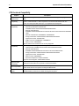
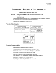
Version Identification
Hardware Identification
Firmware Identification
Catalog Number
Circuit Board ID
Firmware ID
Version
IC695CPU310-BB
CP4A1
CPU Primary
2.51 Build 30A1
BOC Build 28A1
CPU Boot
2.50 Build 25A3
CPU Programmable Parts
Part ID
Revision
BIOS
f4_r05
MCU
f4_r07/6/04
FPGA
X05
SDRAM CPLD
C
HW rev EPROM
f4_r05
Updates
IC695CPU310-AA is field upgradeable to firmware version 2.51 by ordering the upgrade kit
below or downloading from the services web site. The hardware is not field upgradeable
Upgrade Kit: 44A752290-G01
Product Documentation
PACSystems CPU Reference Manual, GFK-2222
PACSystems RX3i Hardware and Installation Manual, GFK-2314
TCP/IP Ethernet Communications for the PACSystems, GFK-2224
C Toolkit for PACSystems User’s Manual, GFK-2259
Proficy™ Machine Edition Getting Started, GFK-1868
Proficy Logic Developer – PLC Programming Software Getting Started, GFK-1918
Datasheet, PACSystems RX3i CPU, GFK-2316
IPI, PACSystems RX3i CPU, GFK-2329A (this document)
2
Important Product Information
GFK-2329A
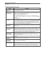
CPU Functional Compatibility
Subject
Description
Programmer Version
Requirements
Machine Edition Logic Developer 5.0 or later must be used to configure and program the
RX3i.
C Toolkit
Compatibility
The C Toolkit for PACSystems is distributed with Machine Edition Logic Developer 5.0 or
greater. Toolkit build 50A1 or later is required for use with the RX3i. Please note: The
Series 90 Toolkit (IC641SWP709/719) is not compatible with PACSystems.
Series 90-30 Module
Compatibility
The PACSystems RX3i supports the following Series 90-30 modules:
Discrete Input Modules: IC693ACC300,
IC693MDL230/231/240/241/632/634/645/646/648/654/655
Discrete Output Modules:
IC693MDL310/330/340/390/730/731/732/733/734/740/741/742/748/752/753/760/930/93
1/940
Discrete Combinational: IC693MAR590, IC693MDR390
Analog I/O Modules: IC693ALG220/221/222/223/390/391/392/442
High Speed Counter: IC693APU300
FANUC I/O Link: IC693BEM320, IC693BEM321
Motion Control: IC693DSM314
All other Series 90-30 modules are not currently supported.
IC694 (blue) Module
Compatibility
The PACSystems RX3i supports the following IC694 modules:
IC694ACC300, IC694MDL230/231/240/241/632/634/645/646/654/655
Discrete Output Modules:
IC694MDL310/330/340/390/732/734/740/741/742/752/753/930/931/940
Analog I/O Modules: IC694ALG220/221/222/223/390/391/392/442
High Speed Counter: IC694APU300
Motion Control: IC694DSM314
Expansion Backplanes: IC694CHS392/398
Expansion Power Supplies: IC694PWR321/330/331
Series 90-30
Expansion Rack
Compatibility
The PACSystems RX3i supports local and remote Series 90-30 expansion racks.
PACSystems RX3i CPUs do not operate in a Series 90-30 Rack.
Series 90-30 Main
Rack Compatibility
Series 90-30 Main Racks cannot be used in a PACSystems RX3i system.
Series 90-30 CPUs do not operate in PACSystemsRX3i Racks.
Isolated 24V
power
In applications that use the IC69xALG220/221/222, consult PACSystems RX3i Hardware and
Installation Manual, GFK-2314 for details of wiring the 24V power.
Important Product Information
3
GFK-2329A
Problems Resolved by this Version
Subject
Description
Extra nuisance faults
on “hot swap” of
ETM001
The extraneous “Reset of, addition of, or extra option module” fault is no longer produced
when an ETM001 is hot-inserted.
Rare unexpected PLC
fault on power up of
expansion rack
In rare instances, an unexpected PLC fault may have occurred during the power up of an
expansion rack. The fault would reference a slot in the expansion rack that contains a
“smart” module. The fault would have been one of:
System configuration mismatch (group = 11)
Option module software failure (group = 16, error code = 1 unsupported board type)
Noncritical CPU software event (group = 140, error code = 121, extra data = 0032 0B0F
8008 0C35)
This no longer occurs.
Overtemp thresholds
are too low
When the operating temperature of the CPU exceeds the normal operating temperature,
system variable #OVR_TMP (%SA8) turns ON and a configurable fault (Fault group 0x18,
error code 0x0001) is reported. A second over-temperature threshold will cause a fatal
error when the CPU has exceeded the critical temperature point just prior to hardware
failure. This is Fault group 0x0D, error code 0x00A8. These thresholds are now set at
58°C and 63°C respectively, rather than at 55°C and 60°C.
Power supply firmware
version reported
incorrectly
The information presented for the power supply in Machine Edition's Device Information
Details window now supplies the version information for the firmware in the power supply,
rather than "N/A".
Verify of Initial Values
of FLASH after powercycle may fail
In previous releases, a verify FLASH operation of initial values after a power-cycle may
indicate that initial values are not equal. The “not equal” is a result of non-retentive
variables being cleared during power-up, when compared with the non-zero values stored
in FLASH. PLC operation has been changed to no longer clear non-retentive variables
during power-up when a read from FLASH is performed as part of power-up, therefore
non-retentive variables will have the values read from FLASH in this case.
At high temperatures,
some CPUs don’t
power up properly
Some CPUs may not complete powering up when operating at high temp (above 52°C
with hot neighbors, higher without hot neighbors). The hardware fix included in this
release resolves this behavior.
If the user leaves the CPU powered down for a few minutes, the CPU will cool and power
up properly.
Interrupt block
execution in
STOP/HALTED
In previous releases, interrupt block execution continued when the CPU entered
STOP/HALTED mode. They now stop execution.
CPU in unconfigured
slot results in
STOP/HALTED
The CPU now enters STOP/FAULTED mode, rather than STOP/HALTED mode, if placed
into a slot for which it is not configured.
Invalid PID parameter
causes CPU to fault.
With the PID loop in manual mode, if a negative value (signed INT) is inadvertently
assigned to the Proportion gain (%ref + 5), the CPU would previously fault when a zero is
subsequently written to the %ref+5 register. While the PID function should fault out under
these conditions, the CPU should not. This issue was only observed using the ISA
function. The CPU did not fault when using the IND function under the same conditions.
4
Important Product Information
GFK-2329A
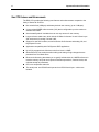
New CPU Features and Enhancements
The RX3i CPU provides the following new features and enhancements compared to the
family of Series 90-30 CPUs:
Non-volatile flash (10Mbyte) and battery-backed user memory (up to 10 Mbytes).
A new register/WORD reference table (%W) that is configurable up to the maximum
available user RAM.
Auto-located Symbolic Variables that can use any amount of user memory.
Larger reference table sizes, which include 32 Kbits for discrete %I and %Q and up to
32K words each for analog %AI and %AQ.
Support for new Rx3i modules, as well as Series 90-30 discrete and analog I/O, and
High Speed Counter.
Application compatibility with PACSystems RX7i applications.
Up to 512 program blocks. Maximum size for a block is 128KB.
Online Edit and Test modes that allow editing and testing of logic changes that are
permitted for a Run Mode Store.
Bit-in-word referencing that allows you to specify individual bits in a WORD reference in
retentive memory as inputs and outputs of Boolean expressions, function blocks, and
calls that accept bit parameters.
CPU over temperature status bit.
Two serial ports: one RS-485 serial port and one RS-232 serial port – neither are
isolated.
Important Product Information
5
GFK-2329A
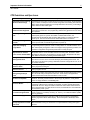
CPU Restrictions and Open Issues
Subject
Description
Ethernet Disconnect During
Word for Word Change
If the Ethernet connection is broken during a word-for-word change, the programmer
may not allow a subsequent word-for-word change after reconnecting due to the fact
that it thinks another programmer is currently attached. If this occurs, you should go
offline and then back online again.
Simultaneous Clears, Loads
and Stores Not Supported
Currently, PACSystems CPUs do not support multiple programmers changing CPU
contents at the same time. The programming software may generate an error during
the operation.
Power Cycle During Online
Edit
If the user stores a folder to flash that is configured to power up from flash and then
subsequently power is cycled in the middle of a Online Edit session, the
programmer will still indicate that the Online Edit session is in progress after the
power cycle. The user should cancel the Online Edit session to continue.
Power Cycle During Write
to Flash
If the CPU is power cycled during the process of writing to flash, and is configured to
power up from flash, a fault will be generated on power up.
Hardware Configuration Not
Equal After Changing
Target Name
If the user stores a hardware configuration to flash which indicates that
“Logic/Config Power up Source” is set to “Always Flash” or “Conditional Flash” and
then subsequently changes the name of the target in the programming software, the
hardware configuration will go Not Equal and will not Verify as equal.
PLC and IO Fault Tables
May Need to be Cleared
Twice to Clear Faulted State
Both PLC and IO fault tables may need to be cleared to take the CPU out of
Stop/Fault mode. If one of the tables contains a recurring fault, the order in which
the tables is cleared may be significant. If the CPU is still in Stop/Fault mode after
both tables are cleared, try clearing the fault tables again.
Setting Force On/Off by
Storing Initial Value
Once a force on or force off has been stored to the PLC, the user cannot switch
from force on to force off or vice-versa directly by downloading initial values. The
user can turn off the force by doing a download, and then change the force on or off
by another download.
Storing Large Numbers of
Blocks to Flash
Currently, storing logic with approximately 200 blocks or more to flash may fail, due
to the programmer timing out.
Number of Active Programs
Returned as Zero
The SNP request Return Controller Type and ID currently returns the number of
active programs as zero.
Serial I/O Failure at 115K
During Heavy Interrupt
Load
Rare data corruption errors have been seen on serial communications when running
at 115K under heavy interrupt load on the PLC. Under heavy load applications,
users should restrict serial communications to 57K or lower.
RAND_MAX and rand()
function incompatible
In the C Toolkit, the RAND_MAX system variable is defined as a 32-bit integer.
However, the rand() function returns a 16-bit integer. By definition, rand() should
return an integer between 0 and RAND_MAX.
Firmware Update Attempt to
Incorrect Module
If an attempt to load Ethernet module firmware is inadvertently directed to a slot
containing a different type of module (for example, an analog module) WinLoader
will fail with the error "Target is unable to enter boot mode. Serial communications
error: Request timed out". After this error occurs, the CPU will be in an invalid state
and should be power cycled.
Incorrect Commreq Status
For Invalid Program Name
The program name for PACSystems is always "LDPROG1". When another program
name is used in a CommReq accessing %L memory, an Invalid Block Name (05D5)
error is generated.
SNP ID not always provided
Unlike the Series 90-30, the RX3i CPU’s SNP ID will not appear in the Machine
Edition programmer Show Status display. Service Request 11 will always return
zeros.
Second programmer can
change logic while in Test &
Edit mode
While currently active in a Test and Edit session using Machine Edition on one PC,
Machine Edition running on another PC is not prevented from storing new logic to
the PLC.
6
Important Product Information
GFK-2329A
Subject
Description
FANUC I/O Master and
Slave operation
Scan sets on the master do not work properly for the first operation of the scan set
after entering RUN mode. They do work properly for subsequent scans.
After downloading a new hardware configuration and logic, a power cycle may be
required to resume FANUC I/O operation.
Use PLCs of similar performance in FANUC I/O networks. If a master or slave is
located in an RX3i system, the other PLCs should be RX3is or Series 90-30
CPU374s.
Must Have Logic If
Powering-Up From Flash
If the application will configure the CPU to retrieve the contents of flash memory at
power-up, be sure to include logic along with hardware configuration when saving to
flash memory.
Avoid Ethernet module
resets
Resetting the Ethernet module, either by Service Request 24 or by the restart
pushbutton, will cause some of the CPU’s internal memory to be consumed if EGD
is configured. The problem becomes more pronounced with larger EGD
configurations. Power-cycling the system will recover the internal memory.
Service Request 24 results
in different fault messages
When Service Request 24 is used to reset a module in the RX3i system, a Reset of
I/O Module fault appears in the PLC fault table. For RX7i systems, two faults
appear: Reset of I/O Module and Loss of I/O Module.
Configuration mismatch
with unsupported module
causes PLC sequence store
failure
If you attempt to store a hardware configuration to the CPU that has a module
configured for a slot that physically contains an unsupported module, the store will
fail with a sequence store failure.
Important Product Information
7
GFK-2329A
CPU Operational Notes
Subject
Slot
numbering,
power supply
placement,
CPU
placement
and reference
Description
1.
The A/C Power-Supply (IC695PSA040) for the RX3i is a doublewide module whose connector
is left justified as viewed when installed in a rack. It cannot be located in Slot 11 of a 12-slot rack
nor Slot 15 of a 16-slot rack. No latch mechanism is provided for the last (right-most) slot in a
rack, therefore it is not possible to place the power-supply in the second to last slot.
2. The RX3i CPU (IC695CPU310) is a doublewide module whose connector is right justified as
viewed when installed in a rack. It is referenced for configuration and by user logic applications by
the leftmost slot that it occupies. For example, if the RX3i CPU has its physical connector inserted
in to slot 4, which means it occupies slots 3 and 4, the CPU is referenced as being located in slot
3. The referenced location of the CPU is not determined by what slot the physical connector is
located in, but rather by the left most slot occupied by the entire module.
3. Due to item #2 above, the RX3i CPU may be located in Slot 0 of a rack (physical connector in
Slot 1). In addition the CPU cannot be located in Slot 11 of a 12-slot rack nor Slot 15 of a 16-slot
rack, since doing so would require the physical connector to be located in the slot reserved for an
expansion module.
4. When migrating a Series 90-30 CPU system to a PACSystems RX3i CPU, be aware that to
maintain the Slot 1 location of the CPU, only a singlewide power-supply may be used in Slot 0.
Currently, the only available singlewide power-supply is a DC power-supply (IC695PSD040).
Therefore, if the application using an existing Series 90-30 system must maintain a Slot 1 CPU
and uses an AC power-supply, the RX3i system must have the RX3i AC power-supply located in a
slot to the right of the RX3i CPU in Slot 1.
5. In deciding to place the CPU in slots other than Slot 1, the user should be aware of the possible
application migration issues that could arise. The following lists the areas that could be affected
when migrating an application from one CPU slot to another.
Item Affected
How Affected
User Logic
Service Request #15
Location of CPU faults will not be the standard 0.1
(Read Last-Logged
location, but will reflect the slot the CPU is located in.
Fault Table Entry)
User logic that decodes fault table entries retrieved
by these service requests may need updating.
Service Request #20
(Read Fault Tables)
Communications
Commreqs directed to the CPU (e.g. those directed
Request (Commreq)
to the serial ports of the CPU) will need to be updated
with the correct CPU slot reference.
H/W
CPU Slot location
Slot location of the CPU must be updated in the HW
Configuration
Configuration to reflect the CPU’s true location.
Fault Tables
Faults logged for the
The location of faults logged for the CPU in the fault
CPU
table will not be the standard 0.1 (rack.slot) location,
but will reflect the CPU’s actual slot.
External
Series 90 PLCs
Devices
Remote Series 90 PLCs that use SRTP Channels COMMREQs expect the CPU
to be in slot 1. In order to support communications with Series 90 SRTP clients
such as Series 90 PLCs using SRTP Channels, the RX3i internally redirects
incoming SRTP requests destined for {rack 0, slot 1} to {rack 0, slot 2}, provided
that the CPU is located in rack 0 slot 2 (and the remote client has not issued an
SRTP Destination service on the connection to discover the rack and slot of the
CPU). This special redirection permits Series 90-30 applications that expect the
power supply to be located leftmost and the CPU to be located to the right of the
power supply to function. Attempts to establish channels with CPUs in slots
other than 1 or 2 will fail if initiated from Series 90 PLCs.
HMI and External Communication Devices
All external communication devices that interact with the CPU should be
checked for compatibility with CPU slot locations other than slot 1. Problems
may arise with, but are not limited to, initial connection sequences and fault
reporting. Machine Edition View customers should select “GE SRTP” as their
communications driver – it can communicate with a CPU in any slot.
Host Communications Toolkit (HCT)
Applications that utilize the Host Communications Toolkit may require updated
drivers.
8
Important Product Information
GFK-2329A
Subject
Description
Important
Installation
Instructions
for Battery
A battery is shipped with the CPU unit behind the battery door on the faceplate but it is not
connected. Do not connect the battery until the CPU is installed in the rack and the rack powered on.
The battery may then be attached to either of the two terminals in the battery compartment. Once
that is done, the CPU may be powered down and normal battery back up operation will begin. To
save battery life, do not connect the battery for the first time until the CPU is powered up.
LD-PLC
operations
Machine Edition LD-PLC no longer supports a function that connects to the PLC, downloads, then
disconnects from the PLC. The connect and download functions are now separate. To perform a
download to the PLC, you must first connect to the PLC.
Logic
Executed in
Row Major
Instead of
Column
Major
Logic execution in PACSystems RX3i is performed in row major order (similar to the Series 90-30).
This is different from the Series 90-70, that executes in column major order. This means that some
complicated rungs may execute slightly differently on PACSystems RX3i and Series 90-70. For
specific examples, see the programming software on-line help.
NaN Handled
Differently
Than in 90-30
The PACSystems RX3i CPU may return slightly different values for Not A Number as compared to
Series 90-30 CPUs. In these exception cases (e.g., 0.0/0.0), power flow out of the function block is
identical to Series 90-30 operation and the computed value is still Not A Number.
PID
Algorithm
Improved
The PID algorithm used in PACSystems has been improved and therefore PID will function slightly
differently on PACSystems RX3i than on the Series 90-30. The differences are that the elapsed time
is computed in 100 µS instead of 10 mS units. This smooths the output characteristic, eliminating
periodic adjustments that occurred when the remainder accumulated to 10mS.
Also, previous non-linear behavior when the integral gain is changed from some value to 1
repeat/second was eliminated.
Some Service
Requests
different from
90-30 or no
longer
supported
Service Requests 6, 15, and 23 have slightly different parameters. Refer to GFK-2222.
PACSystems PLCs support Service Request 26/30 functionality via fault locating references.
The first word of a Service Request command block is required to contain a zero. On the Series 9030, this value was ignored. Please note: the parameter to the service request must be the address of
the location containing the zero.
Service Requests 48 and 49 are no longer supported (there is no auto-restart) because most faults
can be configured to be not fatal.
IL and SFC
IL and SFC are not available.
DO I/O
Instruction
The Series 90-30 Enhanced DO I/O instruction is converted to a standard DO I/O instruction (the
ALT parameter is discarded and ignored.)
END
Instruction
The Series 90-30 END instruction is not supported. Alternate programming techniques should be
used.
Non-nested
JUMP,
LABEL, MCR,
& ENDMCR
Instructions
Non-nested JUMPs, LABELs, MCRs, & ENDMCRs are translated to the corresponding nested
JUMPs, LABELs, MCRs, & ENDMCRs when converting from Series 90-30 to PACSystems RX3i.
Changing IP
Address of
Ethernet
Interface
While
Connected
Storing a hardware configuration with a new IP address to the RX3i while connected via Ethernet will
succeed, then immediately disconnect because the RX3i is now using a different IP address than
the Programmer. You must enter a new IP address in the Target Properties in the Machine Edition
Inspector window before reconnecting.
Duplicate
Station
Address for
Modbus Will
Conflict with
Other Nodes
The default serial protocol for the RX3i is Modbus RTU. The default Station Address is 1. If the PLC
is added to a multi-drop network, care must be taken that the PLC is configured with a unique
Station Address. Nodes with duplicate Station Addresses on the same network will not work
correctly.
Important Product Information
9
GFK-2329A
Subject
Description
Timer
Operation
Care should be taken when timers (ONDTR, TMR, and OFDTR) are used in program blocks that are
NOT called every sweep. The timers accumulate time across calls to the sub-block unless they are
reset. This means that they function like timers operating in a program with a much slower sweep
than the timers in the main program block. For program blocks that are inactive for large periods of
time, the timers should be programmed in such a manner as to account for this catch up feature.
Related to this are timers that are skipped because of the use of the JUMP instruction. Timers that
are skipped will NOT catch up and will therefore not accumulate time in the same manner as if they
were executed every sweep.
Constant
Sweep
Constant Sweep time, when used, should be set at least 10 milliseconds greater than the normal
sweep time to avoid any over-sweep conditions when monitoring or performing on-line changes with
the programmer. Window completion faults will occur if the constant sweep setting is not high
enough.
Large
Number of
COMM_REQs
Sent to
Module in
One Sweep
Causes
Faults
A large number of COMM_REQs (typically greater than 8) sent to a given board in the same sweep
may cause Module Software faults to be logged in the PLC fault table. The fault group is
MOD_OTHR_SOFTWR (16t, 10h) and the error code is COMMREQ_MB_FULL_START (2). When
this occurs, the “FT” output of the function block will also be set. To prevent this situation,
COMM_REQs issued to a given board should be spread across multiple sweeps so that only a
limited number (typically 8 or less) of COMM_REQs are sent to a given board in each sweep. In
addition, the FT output parameter should be checked for errors. If the FT output is set (meaning an
error has been detected), the COMM_REQ could be re-issued by the application logic.
C Block
Standard Math
Functions Do
Not Set errno
In C Blocks, standard math functions (e.g. sqrt, pow, asin, acos) do not set errno to the correct value
and do not return the correct value if an invalid input is provided.
Upgrading
Firmware
The process of upgrading the CPU firmware with the WinLoader utility may fail when multiple IO
modules are in the main rack, due to the time it takes to power cycle the rack system. If the upgrade
process fails, move the CPU to a rack without IO modules and restart the upgrade process.
Winloader initial connect baud rate is fixed at 19200 baud. Note that the firmware download will
occur at 115.2K baud by default.
Note that if you have hyperterm open on a port, and then try to use Winloader on the same port,
Winloader will often say “Waiting for Target” until the hyperterm session is closed.
Hot Swap
Hot Swap of power supplies or CPUs is not supported in this release.
Single Power
Supply
Use only one power supply in an RX3i main rack.
Serial Port
Configuration
COMMREQs
With the following combination of circumstances, it is possible to render serial communications with
the CPU impossible:
1.
2.
3.
4.
User configuration disables the Run/Stop switch
User configures the power up mode to Run or Last
Logic is stored in FLASH and user configures CPU to load from FLASH on power up
User application issues COMMREQs that set the protocol on both of the serial ports to
something that does not permit communications to the ME programmer.