1
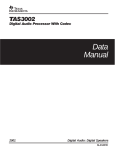
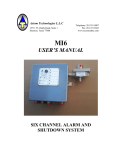
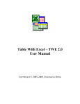
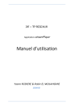
TAS3001 EVM User’s Guide February 2001 Digital Speaker Products SLAU060 IMPORTANT NOTICE Texas Instruments and its subsidiaries (TI) reserve the right to make changes to their products or to discontinue any product or service without notice, and advise customers to obtain the latest version of relevant information to verify, before placing orders, that information being relied on is current and complete. All products are sold subject to the terms and conditions of sale supplied at the time of order acknowledgment, including those pertaining to warranty, patent infringement, and limitation of liability. TI warrants performance of its products to the specifications applicable at the time of sale in accordance with TI’s standard warranty. Testing and other quality control techniques are utilized to the extent TI deems necessary to support this warranty. Specific testing of all parameters of each device is not necessarily performed, except those mandated by government requirements. Customers are responsible for their applications using TI components. In order to minimize risks associated with the customer’s applications, adequate design and operating safeguards must be provided by the customer to minimize inherent or procedural hazards. TI assumes no liability for applications assistance or customer product design. TI does not warrant or represent that any license, either express or implied, is granted under any patent right, copyright, mask work right, or other intellectual property right of TI covering or relating to any combination, machine, or process in which such products or services might be or are used. TI’s publication of information regarding any third party’s products or services does not constitute TI’s approval, license, warranty or endorsement thereof. Reproduction of information in TI data books or data sheets is permissible only if reproduction is without alteration and is accompanied by all associated warranties, conditions, limitations and notices. Representation or reproduction of this information with alteration voids all warranties provided for an associated TI product or service, is an unfair and deceptive business practice, and TI is not responsible nor liable for any such use. Resale of TI’s products or services with statements different from or beyond the parameters stated by TI for that product or service voids all express and any implied warranties for the associated TI product or service, is an unfair and deceptive business practice, and TI is not responsible nor liable for any such use. Also see: Standard Terms and Conditions of Sale for Semiconductor Products. www.ti.com/sc/docs/stdterms.htm Mailing Address: Texas Instruments Post Office Box 655303 Dallas, Texas 75265 Copyright 2001, Texas Instruments Incorporated Notational Conventions Preface Read This First About This Manual This user’s guide describes the operation of the TAS3001 EVM. The user’s guide contains descriptions and schematics for a stereo application. How to Use This Manual This document contains the following chapters: - Chapter 1 Overview Chapter 2 System Components Chapter 3 Board Operation Chapter 4 TAS3001 EVM Block Diagram Chapter 5 MSP430 Microcode Example Appendix A Schematics Notational Conventions This document uses the following conventions. - Program listings, program examples, and interactive displays are shown in a special typeface similar to a typewriter’s. Here is a sample program listing: RESET MOV #Stack,SP ;initialize stack pointer CALL #Setup ;call device setup routine CALL #Set_DCO ;sw calibration of DCO Read This First iii Related Documentation From Texas Instruments Related Documentation From Texas Instruments - TLC320AD77 Literature Number SLAS194 TAS3001 Literature Number SLAS226 MSP430E112 Literature Number SLAS219 TPS7233 Literature Number SLVS102F TLV2362PWR Literature Number SLOS195B FCC Warning This equipment is intended for use in a laboratory test environment only. It generates, uses, and can radiate radio frequency energy and has not been tested for compliance with the limits of computing devices pursuant to subpart J of part 15 of FCC rules, which are designed to provide reasonable protection against radio frequency interference. Operation of this equipment in other environments may cause interference with radio communications, in which case the user at his own expense will be required to take whatever measures may be required to correct this interference. iv Running Title—Attribute Reference Contents 1 Overview . . . . . . . . . . . . . . . . . . . . . . . . . . . . . . . . . . . . . . . . . . . . . . . . . . . . . . . . . . . . . . . . . . . . . . . . 1.1 Description . . . . . . . . . . . . . . . . . . . . . . . . . . . . . . . . . . . . . . . . . . . . . . . . . . . . . . . . . . . . . . . . 1.2 Features . . . . . . . . . . . . . . . . . . . . . . . . . . . . . . . . . . . . . . . . . . . . . . . . . . . . . . . . . . . . . . . . . . 1.3 Environmental Working Conditions . . . . . . . . . . . . . . . . . . . . . . . . . . . . . . . . . . . . . . . . . . . . 1.4 Description of Inputs . . . . . . . . . . . . . . . . . . . . . . . . . . . . . . . . . . . . . . . . . . . . . . . . . . . . . . . . 1.5 Description of Outputs . . . . . . . . . . . . . . . . . . . . . . . . . . . . . . . . . . . . . . . . . . . . . . . . . . . . . . . 1.5.1 Line Output . . . . . . . . . . . . . . . . . . . . . . . . . . . . . . . . . . . . . . . . . . . . . . . . . . . . . . . . . 1.5.2 Power Amplifier Output . . . . . . . . . . . . . . . . . . . . . . . . . . . . . . . . . . . . . . . . . . . . . . . 1.6 Power Supply . . . . . . . . . . . . . . . . . . . . . . . . . . . . . . . . . . . . . . . . . . . . . . . . . . . . . . . . . . . . . . 1-1 1-2 1-3 1-3 1-3 1-3 1-3 1-3 1-3 2 System Components . . . . . . . . . . . . . . . . . . . . . . . . . . . . . . . . . . . . . . . . . . . . . . . . . . . . . . . . . . . . 2.1 Power Supplies and Decoupling . . . . . . . . . . . . . . . . . . . . . . . . . . . . . . . . . . . . . . . . . . . . . . 2.2 Input Amp and Bias . . . . . . . . . . . . . . . . . . . . . . . . . . . . . . . . . . . . . . . . . . . . . . . . . . . . . . . . . 2.3 TLC320AD77—ADC/DAC Functions . . . . . . . . . . . . . . . . . . . . . . . . . . . . . . . . . . . . . . . . . . 2.4 TAS3001—Digital Equalization . . . . . . . . . . . . . . . . . . . . . . . . . . . . . . . . . . . . . . . . . . . . . . . 2.5 Clock Generation . . . . . . . . . . . . . . . . . . . . . . . . . . . . . . . . . . . . . . . . . . . . . . . . . . . . . . . . . . . 2.6 System Microcontroller . . . . . . . . . . . . . . . . . . . . . . . . . . . . . . . . . . . . . . . . . . . . . . . . . . . . . . 2-1 2-2 2-2 2-2 2-2 2-2 2-2 3 Board Operation . . . . . . . . . . . . . . . . . . . . . . . . . . . . . . . . . . . . . . . . . . . . . . . . . . . . . . . . . . . . . . . . . 3.1 Power-Up Sequence . . . . . . . . . . . . . . . . . . . . . . . . . . . . . . . . . . . . . . . . . . . . . . . . . . . . . . . . 3.2 Switch Functions for Digital Equalization . . . . . . . . . . . . . . . . . . . . . . . . . . . . . . . . . . . . . . . 3.3 Software GUI . . . . . . . . . . . . . . . . . . . . . . . . . . . . . . . . . . . . . . . . . . . . . . . . . . . . . . . . . . . . . . 3.4 Software Installation . . . . . . . . . . . . . . . . . . . . . . . . . . . . . . . . . . . . . . . . . . . . . . . . . . . . . . . . 3-1 3-2 3-2 3-3 3-3 4 TAS3001 EVM Block Diagram . . . . . . . . . . . . . . . . . . . . . . . . . . . . . . . . . . . . . . . . . . . . . . . . . . . . . 4-1 4.1 TAS3001 EVM Block Diagram . . . . . . . . . . . . . . . . . . . . . . . . . . . . . . . . . . . . . . . . . . . . . . . . 4-2 4.2 PCB Silkscreen . . . . . . . . . . . . . . . . . . . . . . . . . . . . . . . . . . . . . . . . . . . . . . . . . . . . . . . . . . . . . 4-3 5 MSP430 Microcode Example . . . . . . . . . . . . . . . . . . . . . . . . . . . . . . . . . . . . . . . . . . . . . . . . . . . . . 5-1 A Schematics . . . . . . . . . . . . . . . . . . . . . . . . . . . . . . . . . . . . . . . . . . . . . . . . . . . . . . . . . . . . . . . . . . . . . A-1 Chapter Title—Attribute Reference v Running Title—Attribute Reference Figures 4–1 4–2 TAS3001 EVM Block Diagram . . . . . . . . . . . . . . . . . . . . . . . . . . . . . . . . . . . . . . . . . . . . . . . . . . 4-2 PCB Silkscreen . . . . . . . . . . . . . . . . . . . . . . . . . . . . . . . . . . . . . . . . . . . . . . . . . . . . . . . . . . . . . . . 4-3 Tables 3–1 vi Switch Functions for Speaker Equalization . . . . . . . . . . . . . . . . . . . . . . . . . . . . . . . . . . . . . . . 3-3 Chapter 1 Overview The TAS3001 EVM board demonstrates the operation of the digital equalization and the dramatic improvements that 32-bit digital audio signal processing can make on sound quality. Topic Page 1.1 Description . . . . . . . . . . . . . . . . . . . . . . . . . . . . . . . . . . . . . . . . . . . . . . . . . . . 1-2 1.2 Features . . . . . . . . . . . . . . . . . . . . . . . . . . . . . . . . . . . . . . . . . . . . . . . . . . . . . 1-3 1.3 Environmental Working Conditions . . . . . . . . . . . . . . . . . . . . . . . . . . . . . 1-3 1.4 Description of Inputs . . . . . . . . . . . . . . . . . . . . . . . . . . . . . . . . . . . . . . . . . . 1-3 1.5 Description of Outputs . . . . . . . . . . . . . . . . . . . . . . . . . . . . . . . . . . . . . . . . 1-3 1.6 Power Supply . . . . . . . . . . . . . . . . . . . . . . . . . . . . . . . . . . . . . . . . . . . . . . . . . 1-3 Overview 1-1 Description 1.1 Description This user’s guide describes the operation of the TAS3001 EVM. The user’s guide contains descriptions and schematics for a stereo application. The board described is an example design that can be customized for specific applications. An analog stereo input signal is provided through a 3.5-mm stereo jack. The left and right channels of the signal are filtered and converted into left and right digital signals via the TLC320AD77’s analog-to-digital converter. The digital signals are then equalized by the TAS3001 and converted back to analog via the TLC320AD77’s digital-to-analog converter. The analog left and right signals are amplified at the output stage and piped to the line output to drive amplified speakers via a 3.5-mm stereo jack. The output stage is capable of driving internally-amplified speakers or a stereo amplifier’s line input. Additionally, the speaker equalization board contains a two-channel, 24-watt-per-channel audio power amplifier. The output of the power amplifier is differential; therefore, there are no capacitors in its output circuit that could limit its low frequency response. The output of the power amplifier is connected to RCA connectors. Since the amplifier has a differential output, both terminals of the connection contain the amplified signal. Ensure that neither of these contacts is connected to ground. The power amplifier also contains an LED, labeled CLIP in the silkscreen on the PCB. The LED illuminates when the maximum output power is exceeded or when one of the outputs is shorted to ground. Six switches are used to program the digital equalization of the TAS3001 via the MSP430 microcontroller. The microcontroller provided with this board is preprogrammed for five different EQ settings that can be selected via different combinations of the switches. The switches and EQ settings are described in Section 3.2. This microcontroller, in conjunction with the six switches, can also adjust the volume, bass, and treble settings of the TAS3001. The settings for changing the volume, bass, and treble levels are described in Section 5.2. The MSP430 is placed in a socket so that it can be replaced with a 50-Ω resistor between pins 7 and 13 to reset the board. The board can then be controlled through the DB25 connector. A 25-pin DB25 (male at both ends) is then connected between the EVM and a PC. The cable must have all 25 wires connected (not an RS232 extender cable) and the parallel port on the PC must be set to the EPP mode. If the EPP mode is not available, the bidirectional or PS-2 mode will work in most cases. The TAS3001 EVM is shipped with the 50-Ω resistor installed. If stand-alone operation is desired, an MSP430 microcontroller can be requested from the digital speaker group at Texas Instruments (214–480–3362). This system receives and transmits digital data at a 48-kHz sampling frequency. 1-2 Features 1.2 Features The speaker equalization board has the following features. - 12–V to 18-V-V dc power supply operation Onboard 3.3-V regulator TAS3001 stereo audio digital equalizer Operation via either a preprogrammed MSP430 microcontroller or via a PC through a DB25 male/male cable and software program Six switches used to control volume, bass, treble, and equalization Mute control LED indicates mode of operation A 12.288-MHz master clock frequency 1-Vrms line input and output analog stereo signals sampled at 48 kHz 24-watts-per-channel stereo-differential-output audio power amplifier Diagnostic indicator (CLIP LED) 1.3 Environmental Working Conditions The circuit is designed to operate in an office-type environment. 1.4 Description of Inputs The speaker equalization board uses a 3.5-mm stereo jack for its input. It requires a stereo analog signal input. The analog input ranges from ground to a maximum of 1 Vrms. 1.5 Description of Outputs 1.5.1 Line Output The line output uses a 3.5-mm stereo jack. The output is a stereo analog audio signal with a 1-Vrms level. The output can drive amplified speakers or the line input of a stereo amplifier. 1.5.2 Power Amplifier Output The power amplifier output uses two RCA-type connectors. The power amplifier output signal is capable of driving 4-Ω to 8-Ω speakers. The maximum power amplifier output is 24 watts per channel. 1.6 Power Supply The power supply for the speaker equalization board is 12 V to 18 V (15 V nominal). The board draws an average current of about 0.250 A when driving speakers, and less than 100 mA with no speakers connected. The board can draw greater than 2.5 A peak current when driving speakers at a high volume. Overview 1-3 1-4 Chapter 2 System Components This chapter presents an overview of the system components. Topic Page 2.1 Power Supplies and Decoupling . . . . . . . . . . . . . . . . . . . . . . . . . . . . . . . . 2-2 2.2 Input Amp and Bias . . . . . . . . . . . . . . . . . . . . . . . . . . . . . . . . . . . . . . . . . . . 2-2 2.3 TLC320AD77—ADC/DAC Functions . . . . . . . . . . . . . . . . . . . . . . . . . . . . 2-2 2.4 TAS3001—Digital Equalization . . . . . . . . . . . . . . . . . . . . . . . . . . . . . . . . . 2-2 2.5 Clock Generation . . . . . . . . . . . . . . . . . . . . . . . . . . . . . . . . . . . . . . . . . . . . . 2-2 2.6 System Microcontroller . . . . . . . . . . . . . . . . . . . . . . . . . . . . . . . . . . . . . . . . 2-2 System Components 2-1 Power Supplies and Decoupling 2.1 Power Supplies and Decoupling The system uses a TL78M05 linear regulator to convert the 12 V dc input to 5 V dc to power the operational amplifiers, and a TPS7233 LDO to convert the 5-V power to 3.3 V to power the MSP430, the TAS3001, and the TLC320AD77. All power input pins are decoupled with 0.1 µF capacitors. 2.2 Input Amp and Bias The input to the TLC320AD77 codec is a differential signal and the input to the speaker equalization board is a single-ended stereo signal. The analog front-end buffers the input signal and provides 1.6 V dc for the ADC. The section input amplifier and bias on the schematic (Figure 4–1) describe the analog-front-end circuit and a single-pole low-pass antialiasing filter. The antialiasing filter attenuates unwanted frequencies out of the range of the ADC. The analog front end is independently preformed on the left and right channels via a TLV2362PWR dual high-performance, low voltage operational amplifier. The antialiasing filter is created through a combination of resistors and capacitors on the input of the ADC. 2.3 TLC320AD77—ADC/DAC Functions The speaker equalization board takes an analog stereo audio input signal and converts it to digital so that digital equalization can be performed. The digital signal is then converted back into analog and sent to an external device. The analog-to-digital (A/D) and digital-to-analog (D/A) functions are performed by the TLC320AD77 stereo audio ADA. The TLC320AD77 is a stereo A/D and D/A 24-bit delta-sigma converter. The TLC320AD77 operates at a 48-kHz sampling frequency. The TLC320AD77 serial input option is set to MODE 5, 24-bit I2S operation. 2.4 TAS3001—Digital Equalization The TAS3001 stereo audio digital equalizer is a 32-bit digital audio signal processor. It provides parametric equalization, bass, treble, and volume control, and dynamic range compression. On the speaker equalization board, the TAS3001 operates in slave mode at a 48-kHz sampling frequency. As with the TLC320AD77, the serial audio format is I2S. 2.5 Clock Generation A crystal oscillator provides the master clock for the speaker equalization board. The oscillator runs at 12.288 MHz and provides a 50% duty cycle square wave at 3.3 V peak amplitude. The other IIS timing signals are provided by circuitry in the TAS3001. 2.6 System Microcontroller An EPROM version of the MSP430E112 with 4K bytes of memory is used to control the system because it can be erased and reprogrammed. Future versions of this board will contain the flash memory version of the MSP430. 2-2 Chapter 3 Board Operation This chapter describes the equalization board operation. Topic Page 3.1 Power-Up Sequence . . . . . . . . . . . . . . . . . . . . . . . . . . . . . . . . . . . . . . . . . . . 3-2 3.2 Switch Functions for Digital Equalization . . . . . . . . . . . . . . . . . . . . . . . 3-2 3.3 Software GUI . . . . . . . . . . . . . . . . . . . . . . . . . . . . . . . . . . . . . . . . . . . . . . . . . 3-3 3.4 Software Installation . . . . . . . . . . . . . . . . . . . . . . . . . . . . . . . . . . . . . . . . . . 3-3 Board Operation 3-1 Power-Up Sequence 3.1 Power-Up Sequence The following is the power-up sequence for the speaker equalization board: - Insert either the MSP430 microcontroller or the DB25 PC interface cable into the socket provided on the board, verifying the position of pin 1. Connect 15 V dc to the positive terminal of the power supply jack and connect a ground to the negative terminal. Turn on the power supply and verify that the board draws a current of less than 150 mA. Turn off the power. Connect a 1-Vrms analog signal to the 3.5-mm stereo input jack. This input can be provided either through a signal generator or through a CD player or other sound generation equipment (some CD players provide up to 2 Vrms, which causes distortion). Connect the output to amplified stereo speakers via the 3.5-mm stereo output jack. This output can be measured by a signal analysis or played through speakers. Alternately, connect passive speakers to the amplifier’s output terminals (RCA connectors). Turn on the power to the speaker equalization board and verify again that it draws less than 150 mA of current after the board is initialized by the microcontroller or by the software GUI. Turn on the power to the input and output devices. Depending on the selected mode of operation—either through the MSP430 microcontroller or through the software GUI program and the DB25 cable—introduce equalization to the input analog signal. The instructions for the microcontroller mode of operation are described in section 3.2, and the instructions for the software are described in section 3.3. 3.2 Switch Functions for Digital Equalization When the speaker equalization board is used with an MSP430 microcontroller, the seven onboard switches allow users to adjust the digital equalization, the volume, the base, and the treble of the audio input signal. The MSP430 microcontroller is preprogrammed with five different equalization effects—original or no EQ, flat EQ, jazz EQ, rock EQ, and voice EQ. Since these equalizations are created for a specific type of speaker, they must be reprogrammed for your speakers. The microcontroller is also preprogrammed to increase or decrease the system volume, bass, and treble by 1 dB. There is also a preprogrammed mode that independently resets the bass and the treble to 0 dB. Users can toggle back and forth between EQ mode and volume/bass/treble mode by alternately depressing SW1 and SW6 simultaneously. The LED is on when the board is in EQ mode and off when the board is in volume/bass/treble mode. The first switch on the left performs the shift function. It switches the microcontroller between volume/bass/treble and equalization modes. Alternately, the shift function can be performed by pressing switches #1 and #6. 3-2 Software GUI Table 3–1 describes the operation of the switches and the LED. Table 3–1. Switch Functions for Speaker Equalization SW1 VOL/BASS/TREBLE MODE Volume up: 1 dB Volume down: –1 dB Bass up: 1 dB Bass down: –1 dB Bass reset: 0 dB Treble up: 1 dB Treble down: –1 dB Treble reset: 0 dB SHIFT EQ MODE Mute Original equalization Flat equalization Jazz equalization Rock equalization Voice equalization SW2 SW3 SW4 SW5 SW6 LED X X Off Off Off Off Off Off Off Off X On X On On On On On On X X X X X X X X X X X X X X 3.3 Software GUI When the MSP430 microcontroller is replaced by the DB25 cable, the programming of the TAS3001 equalization can now be done through the software GUI program via a PC. In the software GUI operation mode, the six onboard switches are disabled and the six bands of digital equalization, volume control, bass, and treble are programmed via the software. Refer to the software GUI user’s manual for instructions on the use of this feature. 3.4 Software Installation 1) Set the parallel port on the PC to the EPP mode. (If the EPP mode is not available, bidirectional or PS-2 mode works in most cases.) 2) Create a directory on the PC and install the contents of the supplied disk in it. 3) Run the .exe file and follow the steps on the screen. Board Operation 3-3 3-4 Chapter 4 TAS3001 EVM Block Diagram This chapter presents the TAS3001 EVM block diagram and the printed-circuit board (PCB) silk screen. Topic Page 4.1 TAS3001 EVM Block Diagram . . . . . . . . . . . . . . . . . . . . . . . . . . . . . . . . . . 4-2 4.2 PCB Silkscreen . . . . . . . . . . . . . . . . . . . . . . . . . . . . . . . . . . . . . . . . . . . . . . . 4-3 TAS3001 EVM Block Diagram 4-1 TAS3001 EVM Block Diagram 4.1 TAS3001 EVM Block Diagram Figure 4–1 shows the TAS3001 block diagram. Figure 4–1. TAS3001 EVM Block Diagram 3.5 mm Line_Out R TLC320AD77 _ 3.5 mm Line_In _ R + L L + Power Amplifier _ _ VMID + VCOM MCLK RESET SDOUT + SDIN IIS SDIN SDOUT RESET MCLK TLC3001 Oscillator IIC IIC 3.3 V MSP430 DB25 Connector GUI Interface 4-2 Speaker_Out RCA PCB Silkscreen 4.2 PCB Silkscreen Figure 4–2 shows the printed-circuit board silkscreen. Figure 4–2. PCB Silk Screen Top Silkscreen TAS3001 EVM Block Diagram 4-3 4-4 Chapter 5 MSP430 Microcode Example _CPU_ .set 5 ; ID11X .copy ”STD_DEF.ASM” ; link standard definitions file ;**************************************************************************** ;* MSP430 to Digital TAS3001 EVM board ** ;* ** ;* Brian Merritt ** ;* MSP430 Applications ** ;* rev 2.4G 10/99 ** ;* ** ;**************************************************************************** ; Purpose of program to initialize Digital Speaker part via I2C; perform ; start up of the equalizer board; and act as interface between multifunction ; key switches and Digital Speaker part. 430 does not have to read data from ; DS part (other than acknowledge) so read routines deleted to save memory ; space. Arbitration also deleted since 430 is the only part transmitting ; data. ; ; rev 2.4G - unchanged delay changes in rev F back to rev C, including ; additional delay0 added in F, after finding typo in rev F. ; ;**************************************************************************** ; Definitions ;**************************************************************************** ;********************* Stack .EQU 00210h I_vectors .EQU 0FFFFh Main .EQU 0F000h ;********************* SCL .EQU 010h SDA .EQU 020h SCLIN .EQU 020h SDAIN .EQU 020h SCLDAT .EQU 021h SDADAT .EQU 021h SCLEN .EQU 022h SDAEN .EQU 022h SCLFUNC .EQU 026h SDAFUNC .EQU 026h 11x standard locations ;stackpointer ;Interrupt vectors in ROM ;ROM start on x112 I2C pins and I/O registers ;P1.4 functions as SCL line (pull-up required) ;P1.5 functions as SDA line (pull-up required) ;clock in = P1 input register (P1IN) ;data in = P1 input register (P1IN) ;clock out = P1 output register (P1OUT) ;data out = P1 output register (P1OUT) ;clock enable = P1 direction register (P1DIR) ;data enable = P1 direction register (P1DIR) ;fuction = P1 function select register (P1SEL) ;fuction = P1 function select register (P1SEL) MSP430 Microcode Example 5-1 ;*********************** I2C register Tbl_Pntr .EQU R4 ;pointer for position in total data table Strng_Pntr .EQU R5 ;pointer for position in current byte string Mask .EQU R6 ;used to test level of bits in data byte ;******************** DCO calibration definitions Count1 .set R7 ;Counter for SW DCO calibration Count2 .set R8 ;Counter for SW DCO calibration Delta .set 150 ;SMCLK = 1,228,800 Hz ;******************** Speaker Equal. board definitions OSC_OE .set 080h ;P1.7 functions as oscill enable (active high) RST .set 001h ;P1.0 functions as MIC board reset (active low). ;”RESET” already used elsewhere in this program. EXP .set 008h ;P2.3 functions as expand (active high) ;********************* Key switch/LED/ pins & registers SW1 .equ 08h ;P1.3 equates to switch 1 (active low) SW2 .equ 04h ;P1.2 ” ” 2 ” SW3 .equ 02h ;P1.1 ” ” 3 ” SW4 .equ 01h ;P2.0 ” ” 4 ” SW5 .equ 02h ;P2.1 ” ” 5 ” SW6 .equ 04h ;P2.2 ” ” 6 ” SW1_3IF .equ 023h ;SW1-3 int flags = P1 int flag ;register (P1IFG) SW4_6IF .equ 02Bh ;SW4-6 int flags = P2 int flag register (P2IFG) SW1_3IE .equ 025h ;SW1-3 int enables = P1 int enable register (P1IE) SW4_6IE .equ 02Dh ;SW4-6 int enables = P2 int enable register (P1IE) SW1_3IN .equ 020h ;SW1-3 inputs = P1 input register (P1IN) SW4_6IN .equ 028h ;SW4-6 inputs = P2 input register (P1IN) LED .equ 020h ;P2.5 equates to LED pin (active low) LED_OUT .equ 029h ;LED data out = P2 output register (P2OUT) Vol_Pntr .equ R9 ;pointer for volume setting = data table position Bass_Pntr .equ R10 ;pointer for bass setting = data table position Trbl_Pntr .equ R11 ;pointer for treble setting = data table position MUTE .equ R12 ;current mute setting. 0=mute off, 1=mute on. Trbl_Setpnt .equ R13 ;used to track last manual setting of treble ;needed since treble reset to original with 2 EQs Bass_Setpnt .equ R14 ;used to track last manual setting of bass ;needed since bass reset to original with 2 EQs ;**************************************************************************** ; Main Program ;**************************************************************************** .sect ”MAIN”,Main RESET MOV #Stack,SP ;initialize stackpointer CALL #Setup ;call device setup routine CALL #Set_DCO ;sw calibration of DCO Begin MOV CALL Finish EINT LPM BIS JMP 5-2 #1669,Tbl_Pntr ;set pointer to start of set up data #Loop ;call routine to send I2C BIC.b #EXP,&P2OUT ;set shutdown pin low after I2C code sent ;interrupts enabled after setup complete #LPM3,SR ;go into low pwr mode 3 after DS part is set up LPM ;back to low power mode after interrupt serviced ;**************************************************************************** ; Set Up 11x ;**************************************************************************** Setup MOV #WDTPW+WDTHOLD,&WDTCTL ;stop watchdog timer MOV #TASSEL1+CLR,&TACTL ;clock source for 16-bit ;timer of Timer_A = SMCLK, MOV.b #XTOFF+DIVA1+RSEL2+RSEL0,&BCSCTL1 ;ACLK/4 for DCO cal, ;current into DCO ; (Rsel=6) BIC.b #0FFh,&P1SEL ;set P1 function = I/O BIC.b #0FFh,&P2SEL ;set P2 function = I/O BIC.b #0FEh,&P1OUT ;set P1 output data = low, except reset BIS.b #0C1h,&P1DIR ;set P1 pins-I2C & switches = inputs BIS.b #RST,&P1OUT ;set RESET data = high BIS.b #OSC_OE,&P1OUT ;set oscill enable data = high BIC.b #0FFh,&P2OUT ;set P2 output data = low ;setting for Expand = 0 = off >>>>>>>>>>>>>>>>>>>>>>>>>>>>>>>>>>>>>>>>>>>>>>>>>> CALL #DELAY2 ;delay to let oscill stabilize BIC.b #RST,&P1OUT ;set RESET data = low. pin goes ;low since it is enabled CALL #NOP9 ;delay RESET low to high BIS.b #RST,&P1OUT ;set RESET pin high ;********************* Key switch pins & registers BIC.b #SW1+SW2+SW3,&P1DIR ;switch pins on P1 set to inputs BIC.b #SW4+SW5+SW6,&P2DIR ;switch pins on P2 set to inputs BIS.b #SW1+SW2+SW3,&P1IES ;SW1-3 interrupt edge select = HI to LO BIS.b #SW4+SW5+SW6,&P2IES ;SW4-6 interrupt edge select = HI to LO BIS.b #SW1+SW2+SW3,&SW1_3IE ;SW1-3 interrupts enabled BIS.b #SW4+SW5+SW6,&SW4_6IE ;SW4-6 interrupts enabled BIS.b #EXP+LED,&P2DIR ;set expand & LED pins to outputs BIS.b #LED,&LED_OUT ;LED initial state = off (active low) MOV #180,Vol_Pntr ;initial setting for volume MOV #415,Bass_Pntr ;initial setting for bass MOV #415,Bass_Setpnt ;initial setting for bass MOV #510,Trbl_Pntr ;initial setting for treble MOV #510,Trbl_Setpnt ;initial setting for treble CLR MUTE ;set mute = 0 = initial state of mute = off BIC.b #SW1+SW2+SW3,&SW1_3IF ;clear SW1-3 interrupt flags (P1IFG) BIC.b #SW4+SW5+SW6,&SW4_6IF ;clear SW4-6 interrupt flags (P2IFG) RET ;**************************************************************************** ; Delay routine ;**************************************************************************** DELAY0 push #03000h ;SW Delay using Stack JMP DELAY3 DELAY push #06000h ;SW Delay using Stack JMP DELAY3 DELAY2 push #09000h ;SW Delay using Stack DELAY3 dec 0(SP) ; MSP430 Microcode Example 5-3 jnz DELAY3 ; incd SP ; RET ;**************************************************************************** ; Set_DCO Subroutine: Set DCO to selected frequency. ; Count1 = R8 and Count2 = R9 are used and not saved. ;**************************************************************************** Set_DCO ; JMPskipdco ;>>>>>>>>>>>>>>>>>>>>>>>>>>>>>>>>>>>>>>>>>>>>>> BIS #MC1,&TACTL ;start timer—continous Mode CLR Count1 ;clear counter MOV #CCIS0+CM0+CAP,&CCTL2 ;Define CCR2: capture input signal ;=ACLK, capture on rising edge, ;set to capture mode Test_DCO BIT #CCIFG,&CCTL2 ;intrpt flag set? yes=value captured JZ Test_DCO ;flag not set = loop again BIC #CCIFG,&CCTL2 ;clear interrupt flag AdjDCO MOV &CCR2,Count2 ;contents of cap/com reg2 ->Count2 SUB Count1,Count2 ;Count2-Count1 --> Count2 MOV &CCR2,Count1 ;contents of cap/com reg2 ->Count1 CMP #Delta,Count2 ;Delta=Count2? Delta = SMCLK/(32768/4) JL IncDCO ;jump if Count2 < Delta JEQ DoneDCO ;jump if Count2 = Delta DecDCO DEC.b &DCOCTL ;decrease DCO frequency JMP Test_DCO ;jump to test new setting IncDCO INC.b &DCOCTL ;increase DCO frequency JMP Test_DCO ;jump to test new setting DoneDCO CLR &CCTL2 ;DCO calibrated. stop CCR2 ;skipdco ;>>>>>>>>>>>>>>>>>>>>>>>>>>>>>>>>>>>>>>>>>>>>>>>>>>>>>>>>>>>>>>>>>>>>>>>>>>>> RET ;return from setup / cal routine ;**************************************************************************** ; I2C send & test for end of data ;**************************************************************************** Loop XOR.b #LED,&LED_OUT ;LED momentarily swithed to indicate I2C ;data being sent Loop2 CMP.b #0,Data(Tbl_Pntr) ;first byte in string is no. of data bytes ;to follow before next stop is issued JZ LP_END ;if first byte in string = 0 then end MOV.b Data(Tbl_Pntr),Strng_Pntr ;set string pointer = (table pointer) CALL #I2C ;call routine to send Dig Spkr data byte via I2C JMP Loop2 ;loop to send next data byte string LP_END CALL #DELAY XOR.b #LED,&LED_OUT ;LED switched back to original state = off at ;start up, on in shift (EQ) mode RET ;return from call ;**************************************************************************** ; I2C subroutines ;**************************************************************************** ;******************** send start, set up mask I2C BIS.B #SDA,&SDAEN ;start Condition: set SDA low INC Tbl_Pntr ;increment to first data byte in string 5-4 CALL #NOP9 I2C_Send MOV.b #80h,Mask ;delay before SCL for start low ;bit mask, MSB (bit) first ;******************** test bit, send if low I2C_Send1 BIT.B Mask,Data(Tbl_Pntr) ;bit = 1? JC I2C_Send2 ;jump if bit = 1 BIS.B #SCL,&SCLEN ;data is 0, SCL = low CALL #NOP9 ;delay low portion of clock BIS.B #SDA,&SDAEN ;set SDA = low BIC.B #SCL,&SCLEN ;set SCL (clock) = high ; jmp skip1 ;>>>>>>>>>>>>>>>>>>>>>>>>>>>>>>>>>>>>>>>>>>>>>>>>>>>>>>>>>>>>>>>>>>>>>>>>>>> DS_busy BIT.b #SCL,&SCLIN ;test if DS part busy (C=0) JNC DS_busy ;yes, loop again ;skip1 ;>>>>>>>>>>>>>>>>>>>>>>>>>>>>>>>>>>>>>>>>>>>>>>>>>>>>>>>>>>>>>>>>>>>>>>>>>>>> JMP I2C_Send3 ;******************** send high bit I2C_Send2 BIS.B #SCL,&SCLEN ;data bit = 1: set SCL = low CALL #NOP9 ;delay low portion of clock BIC.B #SDA,&SDAEN ;set SDA = high CALL #NOP9 ;delay BIC.B #SCL,&SCLEN ;set SCL = high ; jmp skip2 ;>>>>>>>>>>>>>>>>>>>>>>>>>>>>>>>>>>>>>>>>>>>>>>>>>>>>>>>>>>>>>>>>>>>>>>>>>>>> DS_busy2 BIT.b #SCL,&SCLIN ;test if DS part busy (C=0) JNC DS_busy2 ;yes, loop again ;skip2 ;>>>>>>>>>>>>>>>>>>>>>>>>>>>>>>>>>>>>>>>>>>>>>>>>>>>>>>>>>>>>>>>>>>>>>>>>>>>> ;******************** shift mask, test for end of byte I2C_Send3 CLRC ;clear carry bit RRC.B Mask ;shift 0 into MSB, shift ”1” right JNCI2C_Send1 ;”1” shifted into carry? ; No = jump send1 CALL #NOP9 ;extend SCL pulse before ackn ; JMP pointers ;>>>>>>>>>>>>>>>>>>>>>>>>>>>>>>>>>>>>>>>>>>>>>>>>>>>>>>>>>>>>>>>>>>>>>>>>>>>> ;******************** check I2C_Ackn BIS.B #SCL,&SCLEN BIC.B #SDA,&SDAEN CALL #NOP8 BIC.B #SCL,&SCLEN Ackn_Test BIT.B #SDA,&SDAIN JC Ackn_Test BIS.b #SDA,&SDAEN acknowledge signal from DS part ;set SCL = low for Acknowledge Bit ;set SDA = high, master releases SDA ;extend SCL low before ackn. ;set SCL = high, master releases SCL ;test for ackn in carry bit (0=Ackn.) ;no ackn (C=1), test again for acknowledge ;hold SDA line low after Ackn. ;******************** change pointers, check for end of string ;pointers ;>>>>>>>>>>>>>>>>>>>>>>>>>>>>>>>>>>>>>>>>>>>>>>>>>>>>>>>>>>>>>>>>>>>>>>>>>>>> INCTbl_Pntr ;increment table pointer next byte in table DECStrng_Pntr ;decrement string pointer JNZI2C_Send ;if not 0 then send next byte ; jmp tempend ;>>>>>>>>>>>>>>>>>>>>>>>>>>>>>>>>>>>>>>>>>>>>>>>>>>>>>>>>>>>>>>>>>>>>>>>>>>>> MSP430 Microcode Example 5-5 ; RET ;>>>>>>>>>>>>>>>>>>>>>>>>>>>>>>>>>>>>>>>>>>>>>>>>>>>>>>>>>>>>>>>>>>>>>>>>> ;******************** stop Condition I2C_Stop BIS.B #SDA,&SDAEN ;set SDA = low BIS.B #SCL,&SCLEN ;set SCL = low CALL #NOP9 ;Delay 18 cycles before issuing stop CALL #NOP9 BIC.B #SCL,&SCLEN ;set SCL = high DS_busy3 BIT.b #SCL,&SCLIN ;test if DS part busy (C=0) JNCDS_busy3 ;yes, loop again CALL #NOP9 BIC.B #SDA,&SDAEN ;set SDA = high ;tempend ;>>>>>>>>>>>>>>>>>>>>>>>>>>>>>>>>>>>>>>>>>>>>>>>>>>>>>>>>>>>>>>>>>>>>>>>>>>>> RET ;******************** delays routines NOP9 NOP ; 9 cycles delay NOP8 RET ; 8 cycles delay ;**************************************************************************** ; Key switch interrupt service routine ;**************************************************************************** SW_ISR ;start of interrupt service routine for key switches DINT ;disable interrupts CALL JMP ;delay for switch debounce ;test for SW1+6 pressed=shift (EQ) mode #SW1,&SW1_3IF ;SW1 pressed? SW2_EQ ;NO, jump to next SW #DELAY2 ;delay before testing 2nd SW #SW6,&SW4_6IF ;SW6 pressed also? TOG_LED ;YES - jump to toggle LED #LED,&LED_OUT ;LED on? (=shift mode) SW1_MUTE ;YES - jump to mute #LED,&LED_OUT ;turn LED on #DELAY ;delay before testing SW again #SW1,&SW1_3IF clear SW1 flag #360,Vol_Pntr ;volume = maximum? SW1_TEST ;Yes - SW1_test #10,Vol_Pntr ;increase pointer to higher setting Vol_Pntr,Tbl_Pntr ;set table pointer = Vol up data #Loop ;call I2C send routine #SW1,P1IN ;SW1 still pressed? SW1_FUNC2 ;YES (active low), increase volume #LED,&LED_OUT ;turn LED off SW_DONE ;jump to end of SW routine #LED,&LED_OUT ;toggle LED when SW1&6 pressed ;= shift mode on/off SW_DONE ;jump to end of SW routine XOR JZ CALL #1,MUTE MUTE_OFF #MUTE_ON SW1_FUNC BIT.b JZ CALL BIT.b JNZ BIT.b JZ SW1_FUNC2 BIC.b CALL BIC.b CMP JEQ ADD MOV CALL SW1_TEST BIT.b JZ BIS.b JMP TOG_LED XOR.b #DELAY2 SW1_MUTE 5-6 ;toggle mute setting (0 = mute off) ;jump if mute=0 - turn mute off ;call mute function (changed to function ;so it could be used elsewhere in program) JMP MUTE_OFF MOV CALL CALL CALL MOV CALL JMP MUTE_ON MOV CALL CALL CALL MOV CALL RET SW_DONE ;jump to end of SW routine Vol_Pntr,Tbl_Pntr ;set table pointer = current Volume #Loop ;call I2C send routine #NOP9 #NOP9 #1655,Tbl_Pntr ;set table pointer to unmute mix data #Loop ;call I2C send routine SW_DONE ;jump to end of SW routine ;turn mute on #1645,Tbl_Pntr ;set table pointer = mute location #Loop ;call I2C send routine #NOP9 #NOP9 #1662,Tbl_Pntr ;set table pointer to mute mix data #Loop ;call I2C send routine ;return from call SW2_EQ BIT.b JZ BIT.b JNZ CALL CALL MOV CALL CALL MOV CALL MOV CALL CALL JMP #SW2,&SW1_3IF SW3_EQ #LED,&LED_OUT SW2_FUNC #MUTE_ON #NOP9 #560,Tbl_Pntr #Loop #DELAY0 #415,Tbl_Pntr #Loop #510,Tbl_Pntr #Loop #DELAY MUTE_OFF ;send EQ ;SW2 pressed? ;NO, jump to next SW ;LED on? (=shift mode) ;NO - jump to SW2 function ;mute before sending EQ ;delay before sending EQ ;set table pointer to start of SW2 EQ ;jump to I2C send routine ;set table pointer to startup bass ;jump to I2C send routine ;set table pointer to startup treb ;jump to I2C send routine ;jump to reset volume SW2_FUNC BIC.b CALL BIC.b CMP JEQ SUB MOV CALL SW2_TEST BIT.b JZ BIS.b JMP SW3_EQ BIT.b JZ CALL BIT.b JNZ BIT.b #LED,&LED_OUT ;turn LED on #DELAY ;delay before testing SW again #SW2,&SW1_3IF ;clear SW2 flag #0,Vol_Pntr ;volume = minimum? SW2_TEST ;Yes - jump to SW2_test #10,Vol_Pntr ;decrease pointer to lower setting Vol_Pntr,Tbl_Pntr ;set table pointer = Vol down data #Loop ;call I2C send routine #SW2,&P1IN ;SW2 still pressed? SW2_FUNC ;YES (active low), decrease volume #LED,&LED_OUT ;turn LED off SW_DONE ;jump to end of SW routine ;send EQ #SW3,&SW1_3IF ;SW3 pressed? SW4_EQ ;NO, jump to next SW #DELAY2 ;delay before testing 4th SW #SW4,&SW4_6IF ;SW4 pressed also? BASS_RST ;YES - jump to reset bass #LED,&LED_OUT ;LED on? (=shift mode) MSP430 Microcode Example 5-7 JNZ SW3_FUNC ;NO CALL #MUTE_ON ;mute CALL #NOP9 MOV #777,Tbl_Pntr CALL #Loop CALL #DELAY0 MOV Bass_Setpnt,Bass_Pntr jump SW3 function before sending EQ ;delay before sending EQ ;set table pointer to start of SW3 EQ ;jump to I2C send routine MOV CALL CALL JMP ;set bass pointer back to last ;manual setting Bass_Pntr,Tbl_Pntr ; #Loop ;call I2C send routine Trbl_Setpnt,Trbl_Pntr ;set treb pointer back to last ;manual setting Trbl_Pntr,Tbl_Pntr ; #Loop ;call I2C send routine #DELAY MUTE_OFF ;jump to rest volume BIC.b CALL BIC.b CMP JEQ ADD MOV #LED,&LED_OUT #DELAY #SW3,&SW1_3IF #460,Bass_Pntr SW3_TEST #5,Bass_Pntr Bass_Pntr,Bass_Setpnt MOV CALL MOV SW3_FUNC MOV Bass_Pntr,Tbl_Pntr CALL #Loop SW3_TEST BIT.b #SW3,&P1IN JZ SW3_FUNC BIS.b #LED,&LED_OUT JMPSW_DONE BASS_RST MOV #415,Bass_Pntr MOV Bass_Pntr,Tbl_Pntr CALL #Loop JMP SW_DONE SW4_EQ BIT.b #SW4,&SW4_6IF JZ SW5_EQ CALL #DELAY2 BIT.b #SW3,&SW1_3IF JNZ BASS_RST BIT.b #LED,&LED_OUT JNZ SW4_FUNC CALL #MUTE_ON CALL #NOP9 MOV #994,Tbl_Pntr CALL #Loop CALL #DELAY0 MOV Bass_Setpnt,Bass_Pntr MOV CALL 5-8 Bass_Pntr,Tbl_Pntr #Loop ;turn LED on ;delay before checking switch again ;clear SW3 flag ;bass = maximum? ;Yes - jump to SW3_test ;increase pointer to higher setting ;bass set point = bass pointer ;tracks last manual bass setting ;set table pointer = bass up data ;call I2C send routine ;SW3 still pressed? ;YES (active low), increase bass ;turn LED off ;jump to end of SW routine ;set bass pointer to startup bass ;set table pointer = bass startup ;jump to I2C send routine ;jump to end of SW routine ;send EQ ;SW4 pressed? ;NO, jump to next SW ;delay before checking SW6 ;SW3 pressed also? ;YES - jump to reset bass ;LED on? (=shift mode) ;NO - jump SW4 function ;mute before sending EQ ;delay before sending EQ ;set table pointer to start of SW4 EQ ;jump to I2C send routine ;set bass pointer back to last ;manual setting ; ;call I2C send routine MOV Trbl_Setpnt,Trbl_Pntr ;set treb pointer back to last ;manual setting MOVTrbl_Pntr,Tbl_Pntr ; CALL #Loop ;call I2C send routine CALL #DELAY JMP MUTE_OFF ;jump to reset volume SW4_FUNC BIC.b CALL BIC.b CMP JEQ SUB MOV MOV CALL SW4_TEST BIT.b JZ BIS.b JMP SW5_EQ BIT.b JZ #LED,&LED_OUT #DELAY #SW4,&SW4_6IF #370,Bass_Pntr SW4_TEST #5,Bass_Pntr Bass_Pntr,Bass_Setpnt Bass_Pntr,Tbl_Pntr #Loop #SW4,&P2IN SW4_FUNC #LED,&LED_OUT SW_DONE #SW5,&SW4_6IF SW6_EQ CALL #DELAY2 BIT.b #SW6,&SW4_6IF JNZ TRBL_RST BIT.b #LED,&LED_OUT JNZ SW5_FUNC CALL #MUTE_ON CALL #NOP9 MOV #1211,Tbl_Pntr CALL #Loop CALL #DELAY0 MOV Bass_Setpnt,Bass_Pntr ;turn LED on ;delay before checking switch again ;clear SW4 flag ;bass = minimum? ;Yes - jump to SW4_test ;decrease pointer to lower setting ;bass set point = bass pointer ;tracks last manual bass setting ;set table pointer = bass down data ;call I2C send routine ;SW4 still pressed? ;YES (active low), decrease bass ;turn LED off ;jump to end of SW routine ;send EQ ;SW5 pressed? ;NO, jump to next SW ;delay before checking SW6 ;SW6 pressed also? ;YES - jump to reset treble ;LED on? (=shift mode) ;NO - jump SW5 function ;mute before sending EQ ;delay before sending EQ ;set table pointer to start of SW5 EQ ;jump to I2C send routine MOV CALL CALL JMP ;set bass pointer back to last ;manual setting Bass_Pntr,Tbl_Pntr ; #Loop ;call I2C send routine Trbl_Setpnt,Trbl_Pntr ;set treb pointer back to last ;manual setting Trbl_Pntr,Tbl_Pntr ; #Loop ;call I2C send routine #DELAY MUTE_OFF ;jump to reset volume BIC.b CALL BIC.b CMP JEQ ADD MOV #LED,&LED_OUT #DELAY #SW5,&SW4_6IF #555,Trbl_Pntr SW5_TEST #5,Trbl_Pntr Trbl_Pntr,Trbl_Setpnt MOV CALL MOV SW5_FUNC ;turn LED on ;delay before checking switch again ;clear SW5 flag ;treble = maximum? ;Yes - jump to SW5_test ;increase pointer to higher setting ;treble set point = treble pointer MSP430 Microcode Example 5-9 MOV CALL SW5_TEST BIT.b JZ BIS.b JMP TRBL_RST MOV MOV CALL JMP SW6_EQ BIT.b JZ Trbl_Pntr,Tbl_Pntr #Loop #SW5,P2IN SW5_FUNC #LED,&LED_OUT SW_DONE #510,Trbl_Pntr Trbl_Pntr,Tbl_Pntr #Loop SW_DONE #SW6,&SW4_6IF SW_DONE CALL #DELAY2 BIT.b #SW1,&SW1_3IF JNZ TOG_LED CALL #NOP9 BIT.b #SW5,&SW4_6IF JNZ TRBL_RST BIT.b #LED,&LED_OUT JNZ SW6_FUNC CALL #MUTE_ON CALL #NOP9 MOV #1428,Tbl_Pntr CALL #Loop CALL #DELAY0 MOV #415,Tbl_Pntr CALL MOV #Loop #510,Tbl_Pntr CALL CALL JMP #Loop #DELAY MUTE_OFF ;tracks last manual treble setting ;set table pointer = treble up data ;call I2C send routine ;SW5 still pressed? ;YES (active low), increase treble ;turn LED off ;jump to reset volume ;set table pointer to startup treble ;set table pointer = treb startup ;jump to I2C send routine ;jump to end of SW routine ;test for SW6 OR SW1+6 pressed ;SW6 pressed? ;NO - jump to SW ISR done ;delay before testing 2nd SW ;SW1 pressed also? ;YES - jump to toggle LED ;delay before checking SW5 ;SW5 pressed also? ;YES - jump to reset treble ;LED on? (=shift mode) ;NO - jump SW6 function ;mute before sending EQ ;delay before sending EQ ;set table pointer to start of SW6 EQ ;call I2C send routine ;set table pointer to startup bass ;setting ;jump to I2C send routine ;set table pointer to startup treble ;setting ;jump to I2C send routine ;jump to reset volume SW6_FUNC BIC.b CALL BIC.b CMP JEQ SUB MOV #LED,&LED_OUT ;turn LED on #DELAY ;delay before checking switch again #SW6,&SW4_6IF ;clear SW6 flag #465,Trbl_Pntr ;treble = minimum? SW6_TEST ;Yes - jump to SW6_test #5,Trbl_Pntr ;decrease pointer to lower setting Trbl_Pntr,Trbl_Setpnt ;treble set point = treble pointer ;tracks last manual treble setting MOV Trbl_Pntr,Tbl_Pntr ;set table pointer = treble down data CALL #Loop ;call I2C send routine SW6_TEST BIT.b #SW6,&P2IN ;SW6 still pressed? JZ SW6_FUNC ;YES (active low), decrease bass BIS.b #LED,&LED_OUT ;turn LED off SW_DONE ;complete interrupt sevice routine CALL #DELAY ;delay for switch debounce when released BIC.b #SW1+SW2+SW3,&SW1_3IF ;clear SW1-3 interrupt flags (P1IFG) 5-10 BIC.b #SW4+SW5+SW6,&SW4_6IF ;clear SW4-6 interrupt flags (P2IFG) EINT ;enable interrupts RETI ;return from ISR ;**************************************************************************** ; Data to be sent to Digital Speaker part via I2C ;**************************************************************************** .EVEN ;Align following section on even address Data .byte 008h ;vol setting = 0 = mute .byte 068h .byte 004h .byte 000h .byte 000h .byte 000h .byte 000h .byte 000h .byte 000h .byte 000h ;IMPORTANT-this line must be included .byte .byte .byte .byte .byte .byte .byte .byte .byte .byte .byte .byte .byte .byte .byte .byte .byte .byte .byte .byte .byte .byte .byte .byte .byte .byte .byte .byte .byte .byte .byte .byte .byte .byte .byte 008h 068h 004h 000h 004h 08Dh 000h 004h 08Dh 000h 008h 068h 004h 000h 005h 01Ch 000h 005h 01Ch 000h 008h 068h 004h 000h 005h 0BBh 000h 005h 0BBh 000h 008h 068h 004h 000h 006h ;line 10 ;IMPORTANT-this line must be included ;vol setting = 2 line 20 ;IMPORTANT-this line must be included ;line 30 ;IMPORTANT-this line must be included ;vol setting = 4 MSP430 Microcode Example 5-11 .byte .byte .byte .byte .byte .byte .byte .byte .byte .byte .byte .byte .byte .byte .byte .byte .byte .byte .byte .byte .byte .byte .byte .byte .byte .byte .byte .byte .byte .byte .byte .byte .byte .byte .byte .byte .byte .byte .byte .byte .byte .byte .byte .byte .byte .byte .byte .byte .byte .byte .byte .byte 5-12 06Eh 000h 006h 06Eh 000h 008h 068h 004h 000h 007h 037h 000h 007h 037h 000h 008h 068h 004h 000h 008h 018h 000h 008h 018h 000h 008h 068h 004h 000h 009h 015h 000h 009h 015h 000h 008h 068h 004h 000h 00Ah 031h 000h 00Ah 031h 000h 008h 068h 004h 000h 00Bh 06Fh 000h ;IMPORTANT-this line must be included ;vol setting = line 50 ;IMPORTANT-this line must be included ;vol setting = 6 ;IMPORTANT-this line must be included ;vol setting = ;IMPORTANT-this line must be included ;vol setting = 8 line 80 ;IMPORTANT-this line must be included ;vol setting = .byte .byte .byte .byte .byte .byte .byte .byte .byte .byte .byte .byte .byte .byte .byte .byte .byte .byte .byte .byte .byte .byte .byte .byte .byte .byte .byte .byte .byte .byte .byte .byte .byte .byte .byte .byte .byte .byte .byte .byte .byte .byte .byte .byte .byte .byte .byte .byte .byte .byte .byte .byte 00Bh 06Fh 000h 008h 068h 004h 000h 00Ch 0D5h 000h 00Ch 0D5h 000h 008h 068h 004h 000h 00Eh 065h 000h 00Eh 065h 000h 008h 068h 004h 000h 010h 027h 000h 010h 027h 000h 008h 068h 004h 000h 012h 020h 000h 012h 020h 000h 008h 068h 004h 000h 014h 056h 000h 014h 056h ;IMPORTANT-this line must be included ;vol setting = 10 line 100 ;IMPORTANT-this line must be included ;vol setting = 11 = -25 dB ;IMPORTANT-this line must be included ;vol setting = 12 line 120 ;IMPORTANT-this line must be included ;vol setting = ;IMPORTANT-this line must be included ;vol setting = 14 line 140 MSP430 Microcode Example 5-13 5-14 .byte .byte .byte .byte .byte .byte .byte .byte .byte .byte .byte .byte .byte .byte .byte .byte .byte .byte .byte .byte .byte .byte .byte .byte .byte .byte .byte .byte .byte .byte .byte 000h 008h 068h 004h 000h 016h 0D1h 000h 016h 0D1h 000h 008h 068h 004h 000h 019h 09Ah 000h 019h 09Ah 000h 008h 068h 004h 000h 01Ch 0B9h 000h 01Ch 0B9h 000h .byte .byte .byte .byte .byte .byte .byte .byte .byte .byte .byte .byte .byte .byte .byte .byte .byte .byte .byte .byte 008h 068h 004h 000h 020h 03Ah 000h 020h 03Ah 000h 008h 068h 004h 000h 024h 029h 000h 024h 029h 000h ;IMPORTANT-this line must be included ;vol setting = ;IMPORTANT-this line must be included ;vol setting = 16 line 160 ;IMPORTANT-this line must be included ;vol setting = ;IMPORTANT-this line must be included ;***** line 180 *********************** ;vol setting = 18 = starting point **** ;IMPORTANT-this line must be included ;vol setting = ;IMPORTANT-this line must be included .byte .byte .byte .byte .byte .byte .byte .byte .byte .byte .byte .byte .byte .byte .byte .byte .byte .byte .byte .byte .byte .byte .byte .byte .byte .byte .byte .byte .byte .byte .byte .byte .byte .byte .byte .byte .byte .byte .byte .byte .byte .byte .byte .byte .byte .byte .byte .byte .byte .byte .byte .byte 008h 068h 004h 000h 028h 093h 000h 028h 093h 000h 008h 068h 004h 000h 02Dh 086h 000h 02Dh 086h 000h 008h 068h 004h 000h 033h 014h 000h 033h 014h 000h 008h 068h 004h 000h 039h 050h 000h 039h 050h 000h 008h 068h 004h 000h 040h 04Eh 000h 040h 04Eh 000h 008h 068h ;vol setting = 20 line 200 ;IMPORTANT-this line must be included ;vol setting = ;IMPORTANT-this line must be included ;vol setting = 22 line 220 ;IMPORTANT-this line must be included ;vol setting = ;IMPORTANT-this line must be included ;vol setting = 24 line 240 ;IMPORTANT-this line must be included ;vol setting = MSP430 Microcode Example 5-15 .byte .byte .byte .byte .byte .byte .byte .byte .byte .byte .byte .byte .byte .byte .byte .byte .byte .byte .byte .byte .byte .byte .byte .byte .byte .byte .byte .byte .byte .byte .byte .byte .byte .byte .byte .byte .byte .byte .byte .byte .byte .byte .byte .byte .byte .byte .byte .byte .byte .byte .byte .byte 5-16 004h 000h 048h 027h 000h 048h 027h 000h 008h 068h 004h 000h 050h 0F4h 000h 050h 0F4h 000h 008h 068h 004h 000h 05Ah 0D5h 000h 05Ah 0D5h 000h 008h 068h 004h 000h 065h 0EAh 000h 065h 0EAh 000h 008h 068h 004h 000h 072h 05Ah 000h 072h 05Ah 000h 008h 068h 004h 000h ;IMPORTANT-this line must be included ;vol setting = 26 line 260 ;IMPORTANT-this line must be included ;vol setting = ;IMPORTANT-this line must be included ;vol setting = 28 line 280 ;IMPORTANT-this line must be included ;vol setting = ;IMPORTANT-this line must be included ;vol setting = 30 line 300 .byte .byte .byte .byte .byte .byte .byte .byte .byte .byte .byte .byte .byte .byte .byte .byte .byte .byte .byte .byte .byte .byte .byte .byte .byte .byte .byte .byte .byte .byte .byte .byte .byte .byte .byte .byte .byte .byte .byte .byte .byte .byte .byte .byte .byte .byte .byte .byte .byte .byte .byte .byte 080h 04Eh 000h 080h 04Eh 000h 008h 068h 004h 000h 08Fh 0F6h 000h 08Fh 0F6h 000h 008h 068h 004h 000h 0A1h 086h 000h 0A1h 086h 000h 008h 068h 004h 000h 0B5h 03Ch 000h 0B5h 03Ch 000h 008h 068h 004h 000h 0CBh 059h 000h 0CBh 059h 000h 008h 068h 004h 000h 0E4h 029h ;IMPORTANT-this line must be included ;vol setting = ;IMPORTANT-this line must be included ;vol setting = 32 line 320 ;IMPORTANT-this line must be included ;vol setting = ;IMPORTANT-this line must be included ;vol setting = 34 line 340 ;IMPORTANT-this line must be included ;vol setting = MSP430 Microcode Example 5-17 5-18 .byte .byte .byte .byte .byte .byte .byte .byte .byte .byte .byte .byte .byte .byte 000h 0E4h 029h 000h 008h 068h 004h 001h 000h 000h 001h 000h 000h 000h .byte .byte .byte .byte .byte .byte .byte .byte .byte .byte .byte .byte .byte .byte .byte .byte .byte .byte .byte .byte .byte .byte .byte .byte .byte .byte .byte .byte .byte .byte .byte .byte .byte .byte .byte .byte 003h 068h 006h 05Dh 000h 003h 068h 006h 05Ah 000h 003h 068h 006h 058h 000h 003h 068h 006h 055h 000h 003h 068h 006h 053h 000h 003h 068h 006h 04Fh 000h 003h 068h 006h 04Bh 000h 003h ;IMPORTANT-this line must be included ;vol setting = 36 = max = 0 dB line 360 ;IMPORTANT-this line must be included ;***** END OF VOLUME DATA *********** ;***** line 370 ********************* ;bass setting = 0 = minimum = -9 db ;IMPORTANT-this line must be included ;bass setting = ;IMPORTANT-this line must be included ;bass setting = 2 line 380 ;IMPORTANT-this line must be included ;bass setting = ;IMPORTANT-this line must be included ;bass setting = 4 line 390 ;IMPORTANT-this line must be included ;bass setting = ;IMPORTANT-this line must be included ;bass setting = 6 line 400 ;IMPORTANT-this line must be included ;bass setting = .byte .byte .byte .byte .byte .byte .byte .byte .byte 068h 006h 046h 000h 003h 068h 006h 042h 000h .byte .byte .byte .byte .byte .byte .byte .byte .byte .byte .byte .byte .byte .byte .byte .byte .byte .byte .byte .byte .byte .byte .byte .byte .byte .byte .byte .byte .byte .byte .byte .byte .byte .byte .byte .byte .byte .byte .byte .byte .byte .byte .byte 003h 068h 006h 03Eh 000h 003h 068h 006h 03Bh 000h 003h 068h 006h 038h 000h 003h 068h 006h 035h 000h 003h 068h 006h 031h 000h 003h 068h 006h 02Eh 000h 003h 068h 006h 02Bh 000h 003h 068h 006h 028h 000h 003h 068h 006h ;IMPORTANT-this line must be included ;bass setting = 8 line 410 ;IMPORTANT-this line must be included ;***** line 415 ****************************** ;bass setting = 9 = mid point = starting point ;IMPORTANT-this line must be included ;bass setting = 10 line 420 ;IMPORTANT-this line must be included ;bass setting = ;IMPORTANT-this line must be included ;bass setting = 12 line 430 ;IMPORTANT-this line must be included ;bass setting = ;IMPORTANT-this line must be included ;bass setting = 14 line 440 ;IMPORTANT-this line must be included ;bass setting = ;IMPORTANT-this line must be included ;bass setting = 16 line 450 ;IMPORTANT-this line must be included ;bass setting = MSP430 Microcode Example 5-19 .byte 025h .byte 000h 5-20 .byte .byte .byte .byte .byte 003h 068h 006h 021h 000h .byte .byte .byte .byte .byte .byte .byte .byte .byte .byte .byte .byte .byte .byte .byte .byte .byte .byte .byte .byte .byte .byte .byte .byte .byte .byte .byte .byte .byte .byte .byte .byte .byte .byte .byte .byte .byte .byte .byte .byte .byte .byte 003h 068h 005h 084h 000h 003h 068h 005h 082h 000h 003h 068h 005h 080h 000h 003h 068h 005h 07Eh 000h 003h 068h 005h 07Ch 000h 003h 068h 005h 07Ah 000h 003h 068h 005h 078h 000h 003h 068h 005h 076h 000h 003h 068h ;IMPORTANT-this line must be included ;***** line 460 ********************* ;bass setting = 18 = maximum = +9 dB ;IMPORTANT-this line must be included ;***** END OF TREBLE DATA *********** ;***** line 465 ********************* ;treble setting 0 = minimum = -9 dB ;IMPORTANT-this line must be included ;treble setting = ;IMPORTANT-this line must be included ;treble setting = 2 line 475 ;IMPORTANT-this line must be included ;treble setting = ;IMPORTANT-this line must be included ;treble setting = 4 line 485 ;IMPORTANT-this line must be included ;treble setting = ;IMPORTANT-this line must be included ;treble setting = 6 line 495 ;IMPORTANT-this line must be included ;treble setting = ;IMPORTANT-this line must be included ;treble setting = 8 line 505 .byte 005h .byte 074h .byte 000h ;IMPORTANT-this line must be included ;***** line 510 ******************************* .byte003h ;treble setting = 9 = starting point ********** .byte 068h .byte 005h .byte 072h .byte 000h ;IMPORTANT-this line must be included .byte 003h ;treble setting = 10 .byte 068h .byte 005h .byte 070h .byte 000h ;IMPORTANT-this line must be included .byte 003h ;treble setting = line 520 .byte 068h .byte 005h .byte 06Dh .byte 000h ;IMPORTANT-this line must be included .byte 003h ;treble setting = 12 .byte 068h .byte 005h .byte 06Bh .byte 000h ;IMPORTANT-this line must be included .byte 003h ;treble setting = line 530 .byte 068h .byte 005h .byte 068h .byte 000h ;IMPORTANT-this line must be included .byte 003h ;treble setting = 14 .byte 068h .byte 005h .byte 065h .byte 000h ;IMPORTANT-this line must be included .byte 003h ;treble setting = line 540 .byte 068h .byte 005h .byte 062h .byte 000h ;IMPORTANT-this line must be included .byte 003h ;treble setting = 16 .byte 068h .byte 005h .byte 05Eh .byte 000h ;IMPORTANT-this line must be included .byte 003h ;treble setting = line 550 .byte 068h .byte 005h .byte 05Ah .byte 000h ;IMPORTANT-this line must be included ;***** line 555 ********************** .byte 003h ;treble setting = 18 = maximum = +9 dB .byte 068h MSP430 Microcode Example 5-21 .byte 005h .byte 055h .byte 000h 5-22 .byte .byte .byte .byte .byte .byte .byte .byte .byte .byte .byte .byte .byte .byte .byte .byte .byte .byte .byte .byte .byte .byte .byte .byte .byte .byte .byte .byte .byte .byte .byte .byte .byte .byte .byte .byte 011h 068h 00Ah 010h 000h 000h 000h 000h 000h 000h 000h 000h 000h 000h 000h 000h 000h 000h 011h 068h 00Bh 010h 000h 000h 000h 000h 000h 000h 000h 000h 000h 000h 000h 000h 000h 000h .byte .byte .byte .byte .byte .byte .byte .byte 011h 068h 00Ch 010h 000h 000h 000h 000h ;IMPORTANT-this line must be included ;***** END OF TREBLE DATA *********** ;***** line 560 ********************* ;start of EQs for SW2 -- ORIGINAL ;line 578 ;line 596 .byte .byte .byte .byte .byte .byte .byte .byte .byte .byte 000h 000h 000h 000h 000h 000h 000h 000h 000h 000h .byte .byte .byte .byte .byte .byte .byte .byte .byte .byte .byte .byte .byte .byte .byte .byte .byte .byte 011h 068h 00Dh 010h 000h 000h 000h 000h 000h 000h 000h 000h 000h 000h 000h 000h 000h 000h .byte .byte .byte .byte .byte .byte .byte .byte .byte .byte .byte .byte .byte .byte .byte .byte .byte .byte 011h 068h 00Eh 003h 085h 0EAh 007h 00Bh 0D5h 003h 085h 0EAh 0FBh 014h 036h 003h 003h 076h .byte 011h .byte 068h .byte 00Fh MSP430 Microcode Example 5-23 5-24 .byte .byte .byte .byte .byte .byte .byte .byte .byte .byte .byte .byte .byte .byte .byte 00Fh 0DAh 043h 0E0h 04Bh 07Ah 00Fh 0DAh 043h 0E0h 04Bh 0D3h 00Fh 0B4h 0DFh .byte .byte .byte .byte .byte .byte .byte .byte .byte .byte .byte .byte .byte .byte .byte .byte .byte .byte 011h 068h 013h 010h 000h 000h 000h 000h 000h 000h 000h 000h 000h 000h 000h 000h 000h 000h .byte .byte .byte .byte .byte .byte .byte .byte .byte .byte .byte .byte .byte .byte .byte .byte .byte 011h 068h 014h 010h 000h 000h 000h 000h 000h 000h 000h 000h 000h 000h 000h 000h 000h ;end of left EQ for SW2 .byte .byte .byte .byte .byte .byte .byte .byte .byte .byte .byte .byte .byte .byte .byte .byte .byte .byte .byte .byte .byte .byte .byte .byte .byte .byte .byte .byte .byte .byte .byte .byte .byte .byte .byte .byte .byte .byte .byte .byte .byte .byte .byte .byte .byte .byte .byte .byte .byte .byte .byte .byte 000h 011h 068h 015h 010h 000h 000h 000h 000h 000h 000h 000h 000h 000h 000h 000h 000h 000h 000h 011h 068h 016h 010h 000h 000h 000h 000h 000h 000h 000h 000h 000h 000h 000h 000h 000h 000h 011h 068h 017h 003h 085h 0EAh 007h 00Bh 0D5h 003h 085h 0EAh 0FBh 014h 036h MSP430 Microcode Example 5-25 .byte .byte .byte .byte .byte .byte .byte .byte .byte .byte .byte .byte .byte .byte .byte .byte .byte .byte .byte .byte .byte 003h 003h 076h 011h 068h 018h 00Fh 0DAh 043h 0E0h 04Bh 07Ah 00Fh 0DAh 043h 0E0h 04Bh 0D3h 00Fh 0B4h 0DFh .byte 000h .byte .byte .byte .byte .byte .byte .byte .byte .byte .byte .byte .byte .byte .byte .byte .byte .byte .byte .byte .byte .byte .byte .byte .byte .byte .byte 5-26 011h 068h 00Ah 00Fh 056h 0E8h 0E2h 0A7h 053h 00Eh 045h 0E6h 0E2h 0A7h 053h 00Dh 09Ch 0CFh 011h 068h 00Bh 00Fh 0E0h 079h 0E0h 07Fh ;end of right EQ for SW2 ;**************************** ;IMPORTANT-this line must be included ;***** line 777 ************** ;start of EQs for SW3 -- FLAT2 .byte .byte .byte .byte .byte .byte .byte .byte .byte .byte 091h 00Fh 0A1h 020h 0E0h 07Fh 091h 00Fh 081h 09Ah .byte .byte .byte .byte .byte .byte .byte .byte .byte .byte .byte .byte .byte .byte .byte .byte .byte .byte 011h 068h 00Ch 00Fh 064h 0F1h 0ECh 0A5h 01Ch 00Dh 052h 0BEh 0ECh 0A5h 01Ch 00Ch 0B7h 0B0h .byte .byte .byte .byte .byte .byte .byte .byte .byte .byte .byte .byte .byte .byte .byte .byte .byte .byte 011h 068h 00Dh 018h 0CEh 0A8h 0EEh 01Bh 033h 006h 093h 085h 0FAh 065h 075h 003h 017h 0ECh .byte 011h .byte 068h .byte 00Eh MSP430 Microcode Example 5-27 5-28 .byte .byte .byte .byte .byte .byte .byte .byte .byte .byte .byte .byte .byte .byte .byte 010h 00Eh 098h 0E0h 010h 066h 00Fh 0E1h 059h 0E0h 010h 066h 00Fh 0EFh 0F2h .byte .byte .byte .byte .byte .byte .byte .byte .byte .byte .byte .byte .byte .byte .byte .byte .byte .byte 011h 068h 00Fh 010h 010h 02Bh 0E0h 015h 0F6h 00Fh 0DAh 070h 0E0h 015h 0F6h 00Fh 0EAh 09Bh .byte .byte .byte .byte .byte .byte .byte .byte .byte .byte .byte .byte .byte .byte .byte .byte .byte 011h 068h 013h 00Fh 056h 0E8h 0E2h 0A7h 053h 00Eh 045h 0E6h 0E2h 0A7h 053h 00Dh 09Ch ;end of left EQ for SW3 .byte 0CFh .byte .byte .byte .byte .byte .byte .byte .byte .byte .byte .byte .byte .byte .byte .byte .byte .byte .byte .byte .byte .byte .byte .byte .byte .byte .byte .byte .byte .byte .byte .byte .byte .byte .byte .byte .byte .byte .byte .byte .byte .byte .byte .byte .byte .byte .byte .byte .byte .byte .byte 011h 068h 014h 00Fh 0E0h 079h 0E0h 07Fh 091h 00Fh 0A1h 020h 0E0h 07Fh 091h 00Fh 081h 09Ah 011h 068h 015h 00Fh 064h 0F1h 0ECh 0A5h 01Ch 00Dh 052h 0BEh 0ECh 0A5h 01Ch 00Ch 0B7h 0B0h 011h 068h 016h 010h 000h 000h 000h 000h 000h 000h 000h 000h 000h 000h MSP430 Microcode Example 5-29 .byte .byte .byte .byte .byte .byte .byte .byte .byte .byte .byte .byte .byte .byte .byte .byte .byte .byte .byte .byte .byte .byte .byte .byte .byte .byte .byte .byte .byte .byte .byte .byte .byte .byte .byte .byte .byte .byte .byte .byte 000h 000h 000h 000h 011h 068h 017h 010h 00Eh 098h 0E0h 010h 066h 00Fh 0E1h 059h 0E0h 010h 066h 00Fh 0EFh 0F2h 011h 068h 018h 010h 010h 02Bh 0E0h 015h 0F6h 00Fh 0DAh 070h 0E0h 015h 0F6h 00Fh 0EAh 09Bh .byte 000h .byte .byte .byte .byte .byte .byte .byte 5-30 011h 068h 00Ah 00Fh 08Bh 038h 0E1h ;end of right EQ for SW3 ;**************************** ;IMPORTANT-this line must be included ;***** line 994 ********************* ;start of EQs for SW4 -- JAZZ .byte .byte .byte .byte .byte .byte .byte .byte .byte .byte .byte .byte .byte .byte .byte .byte .byte .byte .byte .byte .byte .byte .byte .byte .byte .byte .byte .byte .byte 0E8h 00Fh 00Eh 0DDh 012h 0E1h 0E4h 099h 00Eh 06Bh 0C0h 011h 068h 00Bh 00Fh 011h 08Bh 0EDh 024h 072h 00Dh 015h 0FCh 0EDh 012h 028h 00Ch 039h 0D2h .byte .byte .byte .byte .byte .byte .byte .byte .byte .byte .byte .byte .byte .byte .byte .byte .byte .byte 011h 068h 00Ch 010h 004h 04Dh 0E0h 00Bh 034h 00Fh 0F1h 08Ah 0E0h 00Bh 035h 00Fh 0F5h 0D6h .byte 011h .byte 068h .byte 00Dh MSP430 Microcode Example 5-31 5-32 .byte .byte .byte .byte .byte .byte .byte .byte .byte .byte .byte .byte .byte .byte .byte 010h 000h 0E3h 0E0h 002h 0B7h 00Fh 0FDh 010h 0E0h 002h 0B7h 00Fh 0FDh 0F4h .byte .byte .byte .byte .byte .byte .byte .byte .byte .byte .byte .byte .byte .byte .byte .byte .byte .byte 011h 068h 00Eh 045h 04Ch 047h 0FAh 08Bh 06Dh 0DFh 04Eh 061h 00Ch 02Ah 0BEh 002h 0FBh 055h .byte .byte .byte .byte .byte .byte .byte .byte .byte .byte .byte .byte .byte .byte .byte .byte .byte 011h 068h 00Fh 010h 000h 000h 000h 000h 000h 000h 000h 000h 000h 000h 000h 000h 000h .byte 000h .byte .byte .byte .byte .byte .byte .byte .byte .byte .byte .byte .byte .byte .byte .byte .byte .byte .byte 011h 068h 013h 00Fh 08Bh 038h 0E1h 0E8h 00Fh 00Eh 0DDh 012h 0E1h 0E4h 099h 00Eh 06Bh 0C0h .byte .byte .byte .byte .byte .byte .byte .byte .byte .byte .byte .byte .byte .byte .byte .byte .byte .byte .byte .byte .byte .byte .byte .byte .byte .byte .byte .byte .byte .byte .byte 011h 068h 014h 00Fh 011h 08Bh 0EDh 024h 072h 00Dh 015h 0FCh 0EDh 012h 028h 00Ch 039h 0D2h 011h 068h 015h 010h 004h 04Dh 0E0h 00Bh 034h 00Fh 0F1h 08Ah 0E0h ;end of left EQ for SW4 MSP430 Microcode Example 5-33 .byte .byte .byte .byte .byte .byte .byte .byte .byte .byte .byte .byte .byte .byte .byte .byte .byte .byte .byte .byte .byte .byte .byte .byte .byte .byte .byte .byte .byte .byte .byte .byte .byte .byte .byte .byte .byte .byte .byte .byte .byte .byte .byte .byte .byte .byte .byte .byte .byte .byte .byte .byte 5-34 00Bh 035h 00Fh 0F5h 0D6h 011h 068h 016h 010h 000h 0E3h 0E0h 002h 0B7h 00Fh 0FDh 010h 0E0h 002h 0B7h 00Fh 0FDh 0F4h 011h 068h 017h 045h 04Ch 047h 0FAh 08Bh 06Dh 0DFh 04Eh 061h 00Ch 02Ah 0BEh 002h 0FBh 055h 011h 068h 018h 010h 000h 000h 000h 000h 000h 000h 000h .byte .byte .byte .byte .byte .byte .byte 000h 000h 000h 000h 000h 000h 000h .byte 000h .byte .byte .byte .byte .byte .byte .byte .byte .byte .byte .byte .byte .byte .byte .byte .byte .byte .byte .byte .byte .byte .byte .byte .byte .byte .byte .byte .byte .byte .byte .byte .byte .byte .byte .byte .byte 011h 068h 00Ah 00Fh 0EDh 016h 0E0h 025h 0D4h 00Fh 0EDh 016h 0E0h 025h 0EAh 00Fh 0DAh 043h 011h 068h 00Bh 00Fh 08Bh 038h 0E1h 0E8h 00Fh 00Eh 0DDh 012h 0E1h 0E4h 099h 00Eh 06Bh 0C0h ;end of right EQ for SW4 ;**************************** ;IMPORTANT-this line must be included ;***** line 1211 ******************** ;start of EQs for SW5 -- ROCK .byte 011h .byte 068h .byte 00Ch MSP430 Microcode Example 5-35 5-36 .byte .byte .byte .byte .byte .byte .byte .byte .byte .byte .byte .byte .byte .byte .byte 00Fh 011h 08Bh 0EDh 024h 072h 00Dh 015h 0FCh 0EDh 012h 028h 00Ch 039h 0D2h .byte .byte .byte .byte .byte .byte .byte .byte .byte .byte .byte .byte .byte .byte .byte .byte .byte .byte 011h 068h 00Dh 010h 010h 02Bh 0E0h 015h 0F6h 00Fh 0DAh 070h 0E0h 015h 0F6h 00Fh 0EAh 09Bh .byte .byte .byte .byte .byte .byte .byte .byte .byte .byte .byte .byte .byte .byte .byte .byte .byte 011h 068h 00Eh 010h 00Eh 098h 0E0h 010h 066h 00Fh 0E1h 059h 0E0h 010h 066h 00Fh 0EFh .byte 0F2h .byte .byte .byte .byte .byte .byte .byte .byte .byte .byte .byte .byte .byte .byte .byte .byte .byte .byte 011h 068h 00Fh 045h 04Ch 047h 0FAh 08Bh 06Dh 0DFh 04Eh 061h 00Ch 02Ah 0BEh 002h 0FBh 055h .byte .byte .byte .byte .byte .byte .byte .byte .byte .byte .byte .byte .byte .byte .byte .byte .byte .byte 011h 068h 013h 00Fh 0EDh 016h 0E0h 025h 0D4h 00Fh 0EDh 016h 0E0h 025h 0EAh 00Fh 0DAh 043h .byte .byte .byte .byte .byte .byte .byte .byte .byte .byte .byte .byte 011h 068h 014h 00Fh 08Bh 038h 0E1h 0E8h 00Fh 00Eh 0DDh 012h ;end of left EQ for SW5 MSP430 Microcode Example 5-37 .byte .byte .byte .byte .byte .byte .byte .byte .byte .byte .byte .byte .byte .byte .byte .byte .byte .byte .byte .byte .byte .byte .byte .byte .byte .byte .byte .byte .byte .byte .byte .byte .byte .byte .byte .byte .byte .byte .byte .byte .byte .byte .byte .byte .byte .byte .byte .byte .byte .byte .byte .byte 5-38 0E1h 0E4h 099h 00Eh 06Bh 0C0h 011h 068h 015h 00Fh 011h 08Bh 0EDh 024h 072h 00Dh 015h 0FCh 0EDh 012h 028h 00Ch 039h 0D2h 011h 068h 016h 010h 010h 02Bh 0E0h 015h 0F6h 00Fh 0DAh 070h 0E0h 015h 0F6h 00Fh 0EAh 09Bh 011h 068h 017h 010h 00Eh 098h 0E0h 010h 066h 00Fh .byte .byte .byte .byte .byte .byte .byte .byte .byte .byte .byte .byte .byte .byte .byte .byte .byte .byte .byte .byte .byte .byte .byte .byte .byte .byte 0E1h 059h 0E0h 010h 066h 00Fh 0EFh 0F2h 011h 068h 018h 045h 04Ch 047h 0FAh 08Bh 06Dh 0DFh 04Eh 061h 00Ch 02Ah 0BEh 002h 0FBh 055h .byte 000h .byte .byte .byte .byte .byte .byte .byte .byte .byte .byte .byte .byte .byte .byte .byte .byte .byte .byte .byte .byte .byte 011h 068h 00Ah 010h 000h 000h 000h 000h 000h 000h 000h 000h 000h 000h 000h 000h 000h 000h 011h 068h 00Bh ;end of right EQ for SW5 ;**************************** ;IMPORTANT-this line must be included ;***** line 1428 ******************** ;start of EQs for SW6 -- VOICE MSP430 Microcode Example 5-39 5-40 .byte .byte .byte .byte .byte .byte .byte .byte .byte .byte .byte .byte .byte .byte .byte 010h 000h 000h 000h 000h 000h 000h 000h 000h 000h 000h 000h 000h 000h 000h .byte .byte .byte .byte .byte .byte .byte .byte .byte .byte .byte .byte .byte .byte .byte .byte .byte .byte 011h 068h 00Ch 010h 000h 000h 000h 000h 000h 000h 000h 000h 000h 000h 000h 000h 000h 000h .byte .byte .byte .byte .byte .byte .byte .byte .byte .byte .byte .byte .byte .byte .byte .byte .byte 011h 068h 00Dh 00Fh 09Ah 01Fh 0E0h 0CBh 0C2h 00Fh 09Ah 01Fh 0E0h 0CEh 04Ah 00Fh 036h .byte 0C7h .byte .byte .byte .byte .byte .byte .byte .byte .byte .byte .byte .byte .byte .byte .byte .byte .byte .byte 011h 068h 00Eh 001h 01Dh 0D2h 002h 03Bh 0A5h 001h 01Dh 0D2h 0EDh 0FAh 026h 006h 07Dh 023h .byte .byte .byte .byte .byte .byte .byte .byte .byte .byte .byte .byte .byte .byte .byte .byte .byte .byte 011h 068h 00Fh 039h 06Eh 0CAh 099h 027h 059h 02Eh 08Eh 0A5h 0E6h 098h 02Ah 00Ah 08Ch 09Fh .byte .byte .byte .byte .byte .byte .byte .byte .byte .byte .byte .byte 011h 068h 013h 010h 000h 000h 000h 000h 000h 000h 000h 000h ;end of left EQ for SW6 MSP430 Microcode Example 5-41 5-42 .byte .byte .byte .byte .byte .byte 000h 000h 000h 000h 000h 000h .byte .byte .byte .byte .byte .byte .byte .byte .byte .byte .byte .byte .byte .byte .byte .byte .byte .byte .byte .byte .byte .byte .byte .byte .byte .byte .byte .byte .byte .byte .byte .byte .byte .byte .byte .byte .byte .byte .byte .byte .byte .byte .byte .byte .byte 011h 068h 014h 010h 000h 000h 000h 000h 000h 000h 000h 000h 000h 000h 000h 000h 000h 000h 011h 068h 015h 010h 000h 000h 000h 000h 000h 000h 000h 000h 000h 000h 000h 000h 000h 000h 011h 068h 016h 00Fh 09Ah 01Fh 0E0h 0CBh 0C2h .byte .byte .byte .byte .byte .byte .byte .byte .byte .byte .byte .byte .byte .byte .byte .byte .byte .byte .byte .byte .byte .byte .byte .byte .byte .byte .byte .byte .byte .byte .byte .byte .byte .byte .byte .byte .byte .byte .byte .byte .byte .byte .byte .byte .byte 00Fh 09Ah 01Fh 0E0h 0CEh 04Ah 00Fh 036h 0C7h 011h 068h 017h 001h 01Dh 0D2h 002h 03Bh 0A5h 001h 01Dh 0D2h 0EDh 0FAh 026h 006h 07Dh 023h 011h 068h 018h 039h 06Eh 0CAh 099h 027h 059h 02Eh 08Eh 0A5h 0E6h 098h 02Ah 00Ah 08Ch 09Fh .byte 000h .byte .byte .byte .byte 008h 068h 004h 000h ;end of right EQ for SW6 ;**************************************** ;IMPORTANT-this line must be included ;***** line 1645 ************************ ;vol setting = MUTE MSP430 Microcode Example 5-43 .byte .byte .byte .byte .byte .byte 5-44 000h 000h 000h 000h 000h 000h .byte .byte .byte .byte .byte .byte .byte 005h 068h 007h 002h 0D8h 062h 000h .byte .byte .byte .byte .byte .byte .byte 005h 068h 007h 000h 000h 000h 000h .byte .byte .byte .byte .byte .byte .byte .byte .byte .byte .byte .byte .byte .byte .byte .byte .byte .byte .byte .byte .byte .byte .byte .byte .byte 003h 068h 001h 069h 011h 068h 00Ah 010h 000h 000h 000h 000h 000h 000h 000h 000h 000h 000h 000h 000h 000h 000h 011h 068h 00Bh ;IMPORTANT-this line must be included ;***** line 1655 ************************ ;data for unmute of mix1 ;mix1 = -15 dB ;IMPORTANT-this line must be included ;***** line 1662 *********************** ;data for unmute of mix1 ;mix1 = -15 dB ;IMPORTANT-this line must be included ;***** line 1669 ************************ ;beginning of data to be sent at start up ;hex number of bytes before next stop cmd ;(normal mode I2S 18 bit) ;hex number of bytes before next stop cmd ;hex number of bytes before next stop cmd .byte .byte .byte .byte .byte .byte .byte .byte .byte .byte .byte .byte .byte .byte .byte 010h 000h 000h 000h 000h 000h 000h 000h 000h 000h 000h 000h 000h 000h 000h .byte .byte .byte .byte .byte .byte .byte .byte .byte .byte .byte .byte .byte .byte .byte .byte .byte .byte 011h 068h 00Ch 010h 000h 000h 000h 000h 000h 000h 000h 000h 000h 000h 000h 000h 000h 000h ;hex number of bytes before next stop cmd .byte .byte .byte .byte .byte .byte .byte .byte .byte .byte .byte .byte .byte .byte .byte .byte .byte 011h 068h 00Dh 010h 000h 000h 000h 000h 000h 000h 000h 000h 000h 000h 000h 000h 000h ;hex number of bytes before next stop cmd MSP430 Microcode Example 5-45 .byte 000h 5-46 .byte .byte .byte .byte .byte .byte .byte .byte .byte .byte .byte .byte .byte .byte .byte .byte .byte .byte 011h 068h 00Eh 003h 085h 0EAh 007h 00Bh 0D5h 003h 085h 0EAh 0FBh 014h 036h 003h 003h 076h ;hex number of bytes before next stop cmd .byte .byte .byte .byte .byte .byte .byte .byte .byte .byte .byte .byte .byte .byte .byte .byte .byte .byte 011h 068h 00Fh 00Fh 0DAh 043h 0E0h 04Bh 07Ah 00Fh 0DAh 043h 0E0h 04Bh 0D3h 00Fh 0B4h 0DFh ;hex number of bytes before next stop cmd .byte .byte .byte .byte .byte .byte .byte .byte .byte .byte .byte .byte 011h 068h 013h 010h 000h 000h 000h 000h 000h 000h 000h 000h ;hex number of bytes before next stop cmd ;end of left eq’s .byte .byte .byte .byte .byte .byte 000h 000h 000h 000h 000h 000h .byte .byte .byte .byte .byte .byte .byte .byte .byte .byte .byte .byte .byte .byte .byte .byte .byte .byte .byte .byte .byte .byte .byte .byte .byte .byte .byte .byte .byte .byte .byte .byte .byte .byte .byte .byte .byte .byte .byte .byte .byte .byte .byte .byte .byte 011h 068h 014h 010h 000h 000h 000h 000h 000h 000h 000h 000h 000h 000h 000h 000h 000h 000h 011h 068h 015h 010h 000h 000h 000h 000h 000h 000h 000h 000h 000h 000h 000h 000h 000h 000h 011h 068h 016h 010h 000h 000h 000h 000h 000h ;hex number of bytes before next stop cmd ;hex number of bytes before next stop cmd ;hex number of bytes before next stop cmd MSP430 Microcode Example 5-47 .byte .byte .byte .byte .byte .byte .byte .byte .byte .byte .byte .byte .byte .byte .byte .byte .byte .byte .byte .byte .byte .byte .byte .byte .byte .byte .byte .byte .byte .byte .byte .byte .byte .byte .byte .byte .byte .byte .byte .byte .byte .byte .byte .byte .byte .byte .byte .byte .byte .byte .byte .byte 5-48 000h 000h 000h 000h 000h 000h 000h 000h 000h 011h 068h 017h 003h 085h 0EAh 007h 00Bh 0D5h 003h 085h 0EAh 0FBh 014h 036h 003h 003h 076h 011h 068h 018h 00Fh 0DAh 043h 0E0h 04Bh 07Ah 00Fh 0DAh 043h 0E0h 04Bh 0D3h 00Fh 0B4h 0DFh 003h 068h 005h 072h 003h 068h 006h ;hex number of bytes before next stop cmd ;hex number of bytes before next stop cmd ;end of right eq’s ;treble = 0 dB ;bass = 0 dB .byte .byte .byte .byte .byte .byte .byte .byte .byte .byte .byte .byte .byte .byte .byte .byte .byte .byte .byte .byte .byte .byte 03Eh 008h 068h 004h 000h 020h 03Ah 000h 020h 03Ah 005h 068h 007h 002h 0D8h 062h 005h 068h 008h 000h 000h 000h ;volume = -18 dB ;mix1 = -15 dB ;mix2 = mute .byte 000h ;IMPORTANT - this ”000h” indicates end of ;data table it MUST be included for program ;to fuction correctly ;**************************************************************************** ; Interrupt vectors ;**************************************************************************** .even ; Following section must be evenly aligned .sect ”Int_Vect”,I_vectors-31 .word RESET ; no source .word RESET ; no source .word SW_ISR ; P1.x .word SW_ISR ; P2.x .word RESET ; no source .word RESET ; no source .word RESET ; no source .word RESET ; no source .word RESET ; Timer_AX .word RESET ; Timer_A0 .word RESET ; Watchdog/Timer, Timer mode .word RESET ; no source .word RESET ; no source .word RESET ; no source .word RESET ; NMI, Osc. fault .word RESET ; POR, ext. Reset, Watchdog MSP430 Microcode Example 5-49 5-50 Appendix A Schematics This appendix includes a schematic diagram of the TAS3001 EVM. Schematics A-1 A-2