1
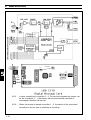
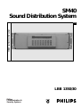
SM40
Sound Distribution System
Instructions for use
Eng
LBB 1350/30
Philips
Communication &
Security Systems
IMPORTANT SAFETY INSTRUCTIONS
1. Read instructions - All the safety and Instructions for use should be read before the
system is operated.
2. Retain instructions - The safety and instructions for use should be retained for future
reference.
3 Heed warnings -All warnings on the unit and in the operating instructions should be
adhered to.
4. Follow instructions - All operating and instructions for use should be followed.
5. Cleaning - Unplug system units from the mains outlet before cleaning. Do not use
liquid cleaners or aerosol cleaners. Use a damp cloth for cleaning.
6. Attachments - Do not use attachments not recommended by the product
manufacture as they may cause hazards.
18. Safety Check - Upon completion of any service or repairs to the units, ask the service
technician to perform safety checks to determine that the unit is in proper operating
condition.
19. Coax Grounding - If an outside cable system is connected to the unit, be sure the
cable is grounded, U.S.A. models only - Section 810 of the National Electrical Code,
ANSI/NFPA No.70-1981, provides information with respect to proper grounding of
the mount and supporting structure, grounding of the coax to a discharge unit, size of
grounding conductors, location of discharge unit, connection to grounding electrodes,
and requirements for the grounding electrode.
20. Lightning - For added protection of the units during a lightning storm, or when it is left
unattended and unused for long periods of time, unplug it from the wall outlet and
disconnect the cable system. This will prevent damage to the unit due to lightning and
power-line surges.
FCC and ICES INFORMATION
(U.S.A and Canadian Models only)
7. Water and Moisture - Do not use this unit near water for example, near a bath tub, wash
bowl, kitchen sink, or laundry tub, in a wet basement, near a swimming pool, in an
unprotected outdoor installation, or any area which is classified as a wet location.
8. Accessories - Do not place this unit on an unstable stand, tripod, bracket, or mount. The
unit may fall, causing serious injury to a person and serious damage to the unit. Use only
with a stand, tripod, bracket, or mount recommended by the manufacturer, or sold with
the product. Any mounting of the unit should follow the manufacturer’s instructions, and
should use a mounting accessory recommended by the manufacturer.
An appliance and cart combination should be moved with care. Quick stops, excessive
force, and uneven surfaces may cause the appliance and cart combination to overturn.
9. Ventilation - Openings in the enclosure, if any, are provided for ventilation and to
ensure reliable operation of the unit and to protect it from overheating. These
openings must not be blocked or covered. The unit should not be placed in a built-in
installation unless proper ventilation is provided or the manufacturers instructions have
been adhered to.
10. Power sources - Units should be operated only from the type of power source
indicated on the marking label. If you are not sure of the type of power supply you
plan to use, consult your appliance dealer or local power company. For units intended
to operate from battery power, or other sources, refer to the instructions for use.
WARNINGS - This equipment has been tested and found to comply with the limits for a
Class A digital device, pursuant to Part 15 of the FCC Rules and ICES-003 of Industry
Canada. These limits are designed to provide reasonable protection against harmful
interference when the equipment is operated in a commercial environment. This
equipment generates, uses, and can radiate radio frequency energy and, if not installed
and used in accordance with the instruction manual, may cause harmful interference to
radio communications. Operation of this equipment in residential area is likely to cause
harmful interference in which case the user will be required to correct the interference
at his own expense. Intentional or unintentional changes or modifications not expressly
approved by the party responsible for compliance shall not be made. Any such changes
or modifications could void the user’s authority to operate the equipment.
If necessary, the user should consult the dealer or an experienced radio/television
technician for corrective action. The user may find the following booklet prepared by the
Federal Communications Commission helpful: “How to identify and Resolve Radio-TV
Interference Problems”. This booklet is available from the U.S. Government Printing
Office, Washington, DC 20402, Stock No. 004-000-00345-4.
SAFETY PRECAUTIONS
11. Grounding or polarization - This unit may be equipped with a polarized alternating
current line plug (a plug having one blade wider than the other). This plug will fit into
the power outlet only one way. This is a safety feature. If you are unable to insert the
plug fully into the outlet, try reversing the plug. If the plug still does not fit, contact
your electrician to replace your obsolete outlet. Do not defeat the safety purpose of
the polarized plug.
Alternatively, this unit may be equipped with a 3-wire grounding type plug, a plug
having a third (grounding) pin. This plug will only fit into a grounding-type power
outlet. This is a safety feature. If you are unable to insert the plug into the outlet,
contact your electrician to replace your obsolete outlet. Do not defeat the safety
purpose of the grounding-type plug.
12. Power-Cord Protection - Power supply cords should be routed so that they are not
likely to be walked on or pinched by items placed upon or against them, paying
particular attention to cords and plugs, convenience receptacles, and the point where
they exit from the appliance.
CAUTION: TO REDUCE THE RISK OF ELECTRICAL
SHOCK, DO NOT OPEN COVERS. NO USER
SERVICEABLE PARTS INSIDE. REFER
SERVICING TO QUALIFIED SERVICE PERSONNEL.
This label may appear on the bottom of the unit due to space limitations.
13. Overloading - Do not overload outlets and extension cords as this can result in a risk
of fire or electrical shock.
14. Object and Liquid Entry - Never push objects of any kind into this unit through
openings as they may touch dangerous voltage points or short-out parts that could
result in a fire or electric shock. Never spill liquid of any kind on the unit.
15. Servicing - Do not attempt to service this unit yourself as opening or removing covers
may expose you to dangerous voltage or other hazards. Refer all servicing to qualified
service personnel.
16. Damage Requiring Service - Unplug the unit from the outlet and refer servicing to
qualified service personnel under the following conditions:
a. When the power-supply cord or plug is damaged.
b. If liquid has been spilt, or objects have fallen into the unit
c. If the unit has been exposed to rain or water.
d. If the unit does not operate normally by following the instructions for use. Adjust
only those controls that are covered by the instructions for use, as an improper
adjustment of other controls may result in damage and will often require extensive
work by a qualified technician to restore the units to their normal operation.
e. If the unit has been dropped or the units has been damaged.
f. When the unit exhibits a distinct change in performance - this indicates a need for
service.
The lightning flash with an arrowhead symbol, with an equilateral triangle, is
intended to alert the user to the presence of uninsulated ‘dangerous voltage’
within the products enclosure that may be of sufficient magnitude to constitute
a risk of electric shock to persons.
The exclamation mark within an equilateral triangle is intended to alert the
user to the presence of important operating and maintenance (servicing)
instructions in the literature accompanying the appliance.
Warning: To prevent fire or shock hazard,
do not expose units not specifically
designed for outdoor use to rain or
moisture.
Attention: Installation should be performed by qualified service personnel
only in accordance with the National Electrical Code or applicable local codes.
Power Disconnect: Units with or without ON-OFF switches have power
supplied to the unit whenever the power cord is inserted into the power
source; however, the unit is operational only when the ON-OFF switch is in
the ON position. The power cord is the main power disconnect for all units.
17. Replacement Parts - When replacement parts are required be sure the service
technician has used replacement parts specified by the manufacturer or have the same
characteristics as the original part. Unauthorized substitutions may result in fire,
electric shock or other hazards.
ALL SPECIFICATIONS SUBJECT TO CHANGE WITHOUT NOTICE. INFORMATION FURNISHED BY PHILIPS COMMUNICATION & SECURITY SYSTEMS. (PCSS) IS BELIEVED TO BE ACCURATE AND
RELIABLE. HOWEVER, NO RESPONSIBILITY OR LIABILITY IS ASSUMED BY PCSS FOR ITS USE, NOR FOR ANY INFRINGEMENTS OR PATENTS OR OTHER RIGHTS OF THIRD PARTIES WHICH
MAY RESULT FROM ITS USE. NO LICENSE IS GRANTED BY IMPLICATION OR OTHERWISE UNDER ANY PATENT OR OTHER RIGHTS OF PCSS
© 1997 by Philips Electronics N.V. All Rights Reserved.
Philips® is a registered trademark of Philips Electronics North America Corporation. Marca(s) Registrada(s).
© 1997 All rights strickly reserved.
Reproduction by third parties in any form is strickly forbidden, unless prior written authorisation has been given. In the continuing quest for product improvement Philips reserves the right to change the
specification of any article or system without prior notice.
i
SM40 SOUND DISTRIBUTION SYSTEM
This page has been left blank intentionally
ii
TABLE OF CONTENTS
1.
GENERAL INTRODUCTION AND OPERATING PRINCIPLES
1.1
Introduction
1.2
Operating Principles
2.
SYSTEM UNPACKING AND INSTALLATION
2.1
Unpacking and installation
2.2
Power Supply Modules
3.
SM 40 BASIC SYSTEM AND EXTENSION FRAME
3.1
Basic System - BS
3.2
Extension Frame - EF
LBB 1350/30
LBB 1360/30
4.
OPERATING AND PROGRAMMING THE SM40 SYSTEM
4.1
Central Processor Card - CPC
4.2
Display and Keyboard - DK
4.3
SM40 Programming
4.3.1 User Programming Menu
4.3.2 Error Messages
4.3.3 Status Display
4.3.4 Installer Programming Menu
5.
SM40 MODULES
5.1
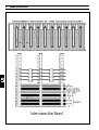
Interconnection Board - IB
5.2
Termination Board
5.2.1 Termination Board - TB
LBB 1377
5.2.2 Matrix Termination Board - MTB
LBB 1371
5.2.3 Relay Termination Board - RTB
LBB 1379
5.3
Input Card - IPC
LBB 1351
5.4
Signal Generator Card - SGC
LBB 1354
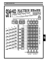
5.5
Matrix Card - MC
LBB 1355
5.6
Control Relay Card - CRC
LBB 1356
5.7
Tone Control Card - TCC
LBB 1357
5.8
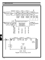
Signal Processing Card - SPC
LBB 1358
5.9
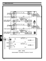
Automatic Volume Control Card - AVC
LBB 1359/00, /09, /21
5.9.1 Automatic Noise Dependent Volume Control (AVC)
5.9.2 Automatic Noise Dependent Audio Signal Processing (ANDAP)
5.9.3 Procedural Description
5.10
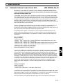
Surveillance Switch Card - SSC
LBB 1374
(Appl. Ext. Audio Source Control)
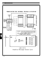
5.11
Digital Message Card - DMC
LBB 1378
5.11.1 Recording and Playback
5.12
Call Station - CST
LBB 9567
5.12.1 Special Applications
5.13
I/O Port (Communications Link) - I/O
LBB 1375/30
6.
REMOTE PROGRAMMING PROTOCOL
6.1
Introduction
6.1
Data Protocols
7.
TECHNICAL DATA
iii
1.
1
GENERAL INTRODUCTION AND OPERATING PRINCIPLES
1.
1.1
GENERAL INTRODUCTION AND OPERATING PRINCIPLES
Introduction
To meet the demand for a comprehensive public address distribution system, a new concept, built around
19 inch rack mounted Euro card circuit boards, has been developed.
Being controlled by a microprocessor, the system is particularly flexible, specific functions being easily
programmed and changed by non technical personnel. In order to meet differing application needs a variety
of circuit cards are available and a wide range of system configurations are possible.
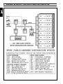
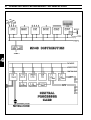
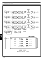
The total public address distribution system comprises:
Call stations; a 19 inch rack unit, containing a microprocessor controlled SM40 centre; and SQ45 power
amplifiers. These in turn feed loudspeakers located in geographical and/or functional zones where people
must be reached with background music, announcements alarm signals and evacuation messages
The SM40 Distribution centre is fed by professional microphones mounted on Call Stations. Each Call
station contains up to 10 user keys, which can be programmed to route the microphone calls, digitally
stored messages, attention tones or alarm signals to one or several power amplifiers.
Because the SM4O centre is designed to handle many different commands simultaneously, a system of
priorities has been developed to cope with conflict situations. A person attempting to call a zone already
being called by someone with a higher priority will not be switched through, and is warned by a red (busy)
LED mounted on the Call station. If the zone is clear to call, or is being called by a station with a lower
priority, a green (talk) LED is illuminated and any lower priority calls are overridden.
All wiring in the SM40 system is particularly installer friendly. Two core screened microphone cable is used
between call stations and central racks, and standard loudspeaker cable between power amplifiers and
loudspeakers.
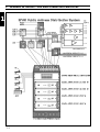
The basic (starter) system, LBB 1350, which can be fed by a maximum of 3 call stations, comprises:
1x Input Card; 1x Central Processing Card; the Display and Keyboard (which is mounted on the front
panel); 1x Signal Generator Card; 1x Matrix Card; 1x Control Relay Card; 1x power supply; plus 1x
Interconnection Board and 3x Termination Boards; tested and mounted in a 19 inch rack frame. The basic
system is capable of controlling 8 amplifiers to feed a maximum of 8 loudspeaker zones.
The single 19 inch rack frame, capable of holding 10 circuit cards, has enough room to accommodate the
basic system plus 5 extra cards. Adding these cards expands the basic system, enabling it to be fed by
additional Call Stations and auxiliary inputs, and to feed more amplifiers.
When a system’s requirements exceed the space offered in a single rack frame, SM40 Extension Frame
LBB 1360 is available. This comprises: 1x power supply; 1x Interconnection Board; and 5x Termination
Boards; tested and mounted in a 19 inch rack frame. 10 SM40 circuit cards fit into each Extension Frame,
and these frames can be linked together to expand the system.
In a maximum configuration, the distribution centre can accept (via a 16 x 64 matrix) up to 16 audio inputs
to feed up to 64 individual amplifier inputs, or (via a 32 x 32 matrix) up to 32 audio inputs to feed up to
32 amplifiers. The basic system is expandable to a maximum of:
8 Input Cards,
32 Matrix Cards,
■ 16 Control Relay Cards (128 make and break contacts).
■ 16 Digital Message Cards,
■ 8 Signal Generator Cards
Plus associated:
■ Tone Control Cards,
■ Automatic Volume Control Cards,
■ Signal Processing Cards.
■
■
Background music can be supplied by a background music player or from a radio tuner, compact disc player,
cassette deck, etc..
1-1
1
1.
GENERAL INTRODUCTION AND OPERATING PRINCIPLES
1
1-2
1.
GENERAL INTRODUCTION AND OPERATING PRINCIPLES
The system, being capable of handling several different signals at the same time, is also ideally suited to
situations where a number of music sources are fed to the same loudspeaker location simultaneously. Typical
applications are hospitals, hotels and nursing homes, where it is required that a choice of music channels are
selectable at each individual loudspeaker cabinet.
Various timer facilities allow tones, recorded messages, and music to be both switched in and routed at
specific times of the day. Days of the week are also selectable.
An ambient noise dependent volume control function is available for installations where continually
changing background noise levels are a problem (e.g. airports, sport stadiums).
As an optional extra, an I/O -PCB is available, which allows the SM40 system to be coupled to a personal
computer via a standard RS232 serial interface. Depending on the software applied the computer can be
used in the ‘active’ or ‘passive’ mode. In the passive mode you can read or record the static information
(system configuration, sources connected) and the ‘dynamic’ information (call logging, auxiliary routing,
failure information). In the ‘active’ mode you can use the computer for up/down loading of the programme,
to program the matrix, or even to operate as a Call station or Master Call station.
Because of their integral music/announcement relays, SQ45 amplifiers are ideally matched to the SM40
centre. During an announcement the preset music level can be automatically overridden, while the
announcement itself comes through at the normal level.
1-3
1
1.
GENERAL INTRODUCTION AND OPERATING PRINCIPLES
1
1-4
1.
1.2
GENERAL INTRODUCTION AND OPERATING PRINCIPLES
OPERATION PRINCIPLES
1
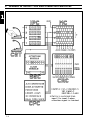
The SM40 Public Address Distribution Centre is easy to use and logical in its operation, it is helpful
however to understand, in principle, how the system works.
Herewith a typical series of actions, initiated by the operator, and carried out by the system:
1.
User Key on Call Station (CST) is pushed (see Chapter 5.12).
2.
Central Processor Card (CPC), which is continuously scanning the system, monitors which User Key
on which CST is being pressed. It then puts into effect a list of orders it was given at its programming
stage (see Chapter 4.1).
3.
First it looks to see which amplifier input, or inputs, our User Key is routed to (see Chapters 4.3.1, 5.3
and 5.12)
4.
Then it makes sure that no other Call Station is currently calling that same input (see Chapter 5.12).
If the requested loudspeaker zone is already being called, the CPC checks which priority rating each
User Key has been given, and if the original caller has a lower priority than the Key being pushed, its
call will be muted and overridden by the new caller.
If the Key being pushed has the same, or a lower priority than the original Key, its call will be ignored,
and a ‘BUSY’ LED mounted on the Call station illuminates to advise that the call has not gone
through.
5.
If all is clear the CPC checks which attention tone and/or pre-recorded message has been programmed
to precede an announcement originating from our User Key, then it switches on the Signal Generator
Card; selects a tone; activates message(s) from the Digital Message Card(s) (DMC’s) and feeds it to the
designated amplifier inputs (see Chapters 5.4 and 5.11).
6.
Meanwhile it sends an electrical signal, via the IPC, back to the CST which energises a flashing green
LED in order to tell the user that the call is going through, but that they will have to wait until the
attention signal has finished (see Chapter 5.12).
7.
If our key was given an alarm tone it will, dependent on the type of tone, be broadcast either for
1 minute, or until the user key is released.
8.
The CPC checks, not only to see where the User Key has been routed to, but whether it has been
given any special orders regarding what it is to do when it gets there. Normally the CPC will mute any
music signal being transmitted to a loudspeaker zone, when an announcement is being broadcast in it.
9.
In order to allow the announcement and/or signal to come through at full volume, regardless of the
volume settings of amplifiers or individual loudspeakers, the CPC switches in a series of corresponding
relays mounted on the Control Relay Card(CRC). These in turn activate the volume control override
circuits of the SQ45 amplifiers and/or individual volume controls in loudspeakers, or loudspeaker
groups (see Chapter 5.6).
10. When the CPC is certain that all is in order, it proceeds to give the message to the Input Card (IPC),
which in turn initiates the Call Station (CST) microphone.
11. The amplifier built into the CST amplifies the audio signal to line level, after which it runs through
the Input Card (IPC); via the Matrix Cards (MC)s; through Tone Control Cards (TCC)s if fitted; via
the Interconnection Board (IB); to the Termination Board (TB); and out to the inputs of the
amplifiers; which in turn feed loudspeakers located in geographical or functional zones.
12. When the announcement is completed and the User Key is released, the system returns to its idle
mode, with the CPC continually scanning, until another call is made. This whole operation is carried
out in less than 1/10th of a second, giving the user the speed and power necessary to communicate in a
clear and efficient manner.
1-5
2. UNPACKING AND INSTALLATION
2
2. UNPACKING AND INSTALLATION
2.1
Unpacking and Installation
In order to ensure that your SM40 Centre functions properly, please follow these few simple instructions
after unpacking your unit.
1.
Carefully check the enclosed system components for physical damage caused during shipping. Any
complaints should be made immediately to the shipping company.
2.
Mount the Basic System frame in the appropriate position in the 19 inch rack unit (not higher than
shoulder height, so that the display and keyboard can be clearly seen).
3.
Extension Frames are available to expand the Basic System into a larger system. These should now be
mounted, and wired according to the appropriate wiring diagrams.
4.
Mount the amplifiers and auxiliary equipment in the rack(s). If power amplifiers are mounted beneath
SM40 frames, a heat shield should be installed above them to deflect hot air currents.
5.
Taking care to avoid earth (ground) loops, wire the mains power to the units.
SM40 will operate successfully on mains voltages from 187 V to 264 V when tapped for 220 V, and
from 90 to 132 V when tapped for 110 V. Be sure to check that your system is wired for the correct
mains voltage. Refer to Chapter 2.2 Power Supply Modules.
Warning: Because it is possible to touch the mains voltage terminals when the frame back panels are
opened, it is advisable not to turn the power on at this stage.
6.
Open the back panel of the Basic system, and check that all of the connectors on the Interconnection
Board and Termination boards are firmly in place. If, in the unlikely event that one of the connectors
has become disconnected, refer to the enclosed basic system wiring diagram.
7.
Referring to Termination Board illustrations in Chapter 5.2, wire the Call Stations, auxiliary input
sources, amplifiers, etc., to the screwblock connectors.
8.
Plug the screwblock connectors into the termination boards, ensuring that they are in the correct
locations.
9.
Open the front panel of the rack frame and gently push each of the circuit cards to make sure that
they are all firmly connected to the Interconnection Board.
10.
If, after double checking that all of the mains power and signal wiring is correct, and that the system is
adequately earthed, switch on the mains power to the rack.
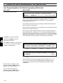
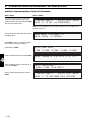
11.
The display on the front panel shows:
* * * SYSTEM MUST BE PROGRAMMED * * *
* * *
GO TO INSTALLER MENU
* * *
For installer programming refer to Chapter 4.3.4.
2-1
2
2. UNPACKING AND INSTALLATION
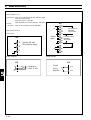
2.2
Power supply Modules
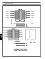
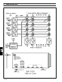
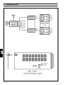
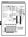
The SM40 Basic System frame LBB 1350 includes a Power Supply Module type SPM 315, and the SM40
Extension frame includes a Power Supply Module type SPM 215. Both modules, with the placement of
jumpers (included on delivery) can be configured for use on either 220 - 230 Volts AC, or 110 - 115 V AC.
To ensure that your SM40 frame operates on the correct voltage, refer to the figure opposite and proceed as
follows:
WARNING: BEFORE WORKING ON A SYSTEM, READ THE SECTION ‘IMPORTANT SAFETY
INSTRUCTIONS’ FOUND AT THE BEGINNING OF THIS MANUAL. ALWAYS DISCONNECT
THE FRAME FROM THE MAINS SUPPLY PRIOR TO WORKING ON THE FRAME ITSELF.
2
1.
SM40 Basic System frame LBB 1350 using Power Supply Module SPM 315
Operation on 110 - 115 V AC
a.
Open the front panel of the rack frame, and gently remove the Power Supply Module
from its housing.
b.
Once the module is removed, unscrew and remove the 2 retaining screws needed to locate the
module’s printed circuit board. Once removed, carefully slide the top cover plate away from the
module itself to reveal the printed circuit board.
c.
On the printed circuit board (component side up) locate the jumper circuit (see figure opposite).
Using the jumper link(s) delivered with the module, place the jumper as shown.
Operation on 220 - 230 V AC
d.
For operation on 220 - 230 V AC (factory setting) DO NOT PLACE the jumper.
2.
SM40 Basic Extension frame LBB 1360 using Power Supply Module SPM 215
Operation on 110 - 115 V AC
a.
Open the front panel of the rack frame and gently remove the Power Supply Module
from its housing.
b.
Once the module is removed, unscrew and remove the 8 retaining screws found on top of the modules
cover plate, needed to locate the module’s printed circuit board. Once removed, carefully slide the top
cover plate away from the module itself to reveal the printed circuit board.
c.
On the printed circuit board (component side up) locate the jumper circuit (see figure opposite).
Using the jumper link(s) delivered with the module, place the three jumper(s) as shown.
Operation on 220 - 230 V AC
d.
For operation on 220 - 230 V AC (factory setting) only 1 jumper link is placed (see opposite).
3.
General
a.
The SM40 Basic System frame LBB 1350 and the SM40 Extension frame LBB 1360 are supplied with
a 3-core mains cable. The mains cable is terminated with a 2-pole mains plug with earth contacts (or
earth pin) for connection to the mains supply, and at the other end with a CEE connector for
connection to the mains socket on the rear of the frame. For use in some countries it may be
necessary to replace the mains cable with one of a local standard type. The wiring is as follows:
- Live/brown
- Neutral/blue
- Earth/green-yellow
WARNING: THE FRAME MUST BE EARTHED VIA THE MAINS SUPPLY USING THE
GREEN/YELLOW WIRE. THE MAINS PLUG MUST BE OF AN EARTHED TYPE.
b.
2-2
Power Supply Module, replacement fuses, are 4 Amps (adaption is not required for alternative
voltages).
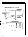
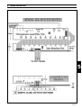
2. UNPACKING AND INSTALLATION
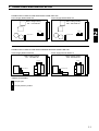
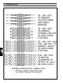
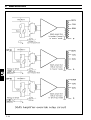
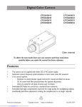
POWER SUPPLY MODULE FOR SM40 BASIC FRAME LBB 1350
Power Supply Module SPM 315
Power Supply Module SPM 315
Mains voltage setting
110 - 115 Volts AC
Mains voltage setting
220 - 230 Volts AC
Fuse 4A
Fuse 4A
1 jumper placed
2
No jumper placed
POWER SUPPLY MODULE FOR SM40 EXTENDED MODULE FRAME LBB 1360
Power Supply Module SPM 215
Power Supply Module SPM 215
Mains voltage setting
110 - 115 Volts AC
Mains voltage setting
220 - 230 Volts AC
Fuse 4A
Fuse 4A
3 jumpers placed
1 jumpers placed
JUMPER PLACEMENT
Jumper open
Jumper placed in position
2-3
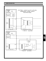
3. SM 40 BASIC SYSTEM AND EXTENSION FRAME
3
3. SM 40 BASIC SYSTEM AND EXTENSION FRAME
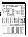
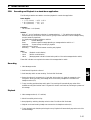
3.1
Basic System - BS
LBB 1350/30
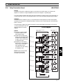
Self contained, fully operational system, around which all SM40 systems are built. Comprises 5 circuit
cards, mounted in a single 19 inch rack frame.
The Basic (starter) System is the heart of the SM40 Public Address Distribution Centre. When
supplemented with a variety of Euro-cards and PCB’s, a wide range of system configurations are possible,
and many different application needs are successfully met.
Containing (along with its other circuit cards) the Central Processor Card (CPC); and the Display and
Keyboard; and because it is mounted in a single rack frame; the Basic System is a self contained, fully
working unit in its own right.
Being fed by a maximum of 3 Call Stations LBB 9567 (ordered separately), it is capable of controlling 8
amplifiers to feed a maximum of 8 loudspeaker zones.
Because the Basic System is supplied fully wired, adjusted, tested, and mounted in its own 19 inch rack unit,
ready for use, it is an ideal model from which to build a larger system.
By running through the Basic System’s programming sequence it is easy to understand how the SM40
concept works. Any larger system has merely a greater quantity of Call Stations (CST)s, auxiliary inputs, etc.
to program, and is dealt with in exactly the same way.
When a system’s requirements exceed the facilities available in the Basic System, further circuit cards (plus
the Extension Frames LBB 1360 necessary to accommodate them) are ordered, expanding the system to
meet specific application needs.
Units included with Basic System LBB 1350:
1x
1x
1x
2x
1x
1x
IB
TB
MTB
DK
1x CPC
1x
1x
1x
1x
CRC
IPC
SGC
MC
Single 19 Inch Rack Frame
Power Supply +15V/-15V/+5V
Interconnection Board
Termination Boards
Matrix Termination Board
Display & Keyboard
(mounted on front panel)
Central Processor Card
Distribution System Software
Control Relay Card
Input Card
Signal Generator Card
Matrix Card
Optional Euro-Cards:
TCC
Tone Control Card
LBB 1357/00
SPC
Signal Processing Card
LBB 1358/00
AVC
Automatic Volume Card LBB 1359/09, /21, /00
Digital Message Card
LBB 1378/00
LBB 1377/00 DMC
LBB 1371/00 SSC
Surveillance Switch Card
LBB 1374/00
CRC
Control Relay Card
LBB 1356/00
IPC
Input Card
LBB 1351/00
Signal Generator Card
LBB 1354/00
LBB 1352/30 SGC
MC
Matrix Card
LBB 1355/00
LBB 1356/00
LBB 1351/00 Optional PCB’s:
LBB 1354/00
Communication PCB
LBB 1366/00
LBB 1355/00 CMP
I/O
I/O - PCB
LBB 1375/00
MTB
Matrix Termination Board
LBB 1371/00
MAP
Microphone Amp PCB
LBB 1364/00
KSP
Key Sensing PCB
LBB 1363/30
KCP
Key Confirm PCB
LBB 1365/00
TB
Termination Board
LBB 1377/00
RTB
Relay Termination Board
LBB 1379/00
Optional Units:
CST
-
Call Station (Standard version)
Extension Frame
LBB 9567/30
LBB 1360/30
3-1
3
3. SM 40 BASIC SYSTEM AND EXTENSION FRAME
3
3-2
3. SM 40 BASIC SYSTEM AND EXTENSION FRAME
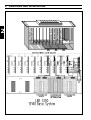
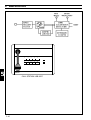
3.2
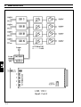
Extension Frame - EF
LBB 1360/30
Single 19 inch rack frame, capable of holding 10 SM40 circuit cards. Complete with power supply,
Interconnection and Termination Boards.
A single rack frame, capable of holding, and interconnecting 10 SM40 circuit cards, has enough room to
accommodate the Basic (starter) System, described elsewhere, plus 1x Input Card, 3x Matrix Cards, and
1x Control Relay Card.
When the quantity of cards required in an SM40 system exceeds the amount of space offered in this single
rack frame, Extension Frame LBB 1360, is available.
Each Extension frame allows expansion of the system by up to 10 circuit cards, so that a system should be
specified as 1x Basic System LBB 1350; plus the extra circuit cards required; plus the quantity of extension
frames needed to accommodate those cards.
Units included with Extension Frame LBB 1360:
1x
1x
1x IB
1x TB
Single 19” rack frame
Power Supply Unit +15V/ -15V
Interconnection Boards
Termination Boards
3
LBB 1377/00
These components, mounted in the 19 inch rack frame, are supplied tested, and wired to accept and power
up to 10 SM40 circuit cards.
Note: All circuit cards controlled by the CPC must be mounted in the basic system and the first 7 extension
frames. All other cards (TCC, SPC, AVC, etc.) may then be mounted in as many frames as are necessary.
A maximum of 40 cards can be connected to one I2C bus. The basic frame includes two I2C busses.
3-3
3. SM 40 BASIC SYSTEM AND EXTENSION FRAME
3
3-4
3. SM 40 BASIC SYSTEM AND EXTENSION FRAME
3
3-5
4. OPERATING AND PROGRAMMING THE SM40 SYSTEM
4
4. OPERATING AND PROGRAMMING THE SM40 SYSTEM
4.1
Central Processor Card - CPC
At the heart of the SM40 Public address Distribution System is the Central Processor Card (CPC). Capable
of controlling 16 or 32 call stations; 320 user keys; 1024 matrix points; 2 x 128 relays, 16 Digital Message
Cards and 8 signal generators; this is a powerful piece of equipment, providing a system of this type with
previously unheard of possibilities.
The basic functions of this card are as follows:
DETECTION of call station user keys. Using information given it by the Input Card (IPC), the unit is
capable of sensing which user key is being pressed.
ROUTING of microphones and attention signal tones (actuated by user keys), alarm tones, digital
messages, background music, etc., via Matrix Card (MC) to amplifiers and loudspeakers located in
geographical and/or functional zones.
USER KEY PRIORITY level setting. To cope with conflict situations (e.g. when 2 call stations attempt to
call the same zones simultaneously) each user key is given a priority level of 0-9, 9 being highest priority.
ATTENTION SIGNAL TONES, are coupled with the user keys so that when a key is pressed the tone will
be broadcast before or instead of an announcement. Dependant on their character these tones may also be
used as alarm signals or test tones.
DIGITAL MESSAGE CARD control, allows per card up to 7 messages with varying duration up to a
maximum of 65 seconds to be recorded, and played back as desired. The maximum number of cards per
centre is 16.
SWITCHING of loudspeaker volume control override circuits, and bypassing of the input attenuators in
the SQ45 amplifiers, via the Control Relay Card (CRC).
SWITCHING of amplifier outputs for loudspeaker group switching, via ‘unlocked’ Control Relay Cards.
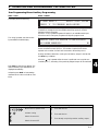
CHECKING of system hardware. The processor acts as a “watchdog”, continuously scanning the SM40
system hardware to check for errors, malfunctions or disconnections. If a problem exists a message is
displayed on the lcd screen of the Display & Keyboard; for instance if Call Station 3 is disconnected the
message displayed is:
* * * * ERROR * * * *
CALL/ALARM STATION 03
REAL TIME CLOCK is built into the unit, and is displayed, giving date, hours and minutes. A timer
facility is coupled to the clock, making it possible to switch on and route tones, recorded messages and
music at specific times of the day, or week.
A yellow LED, mounted on the front edge of the (CPC) card advises that the unit is running with the rest
of the SM40 system, and 1 green LED indicates that adequate supply voltage is present.
A Display & Keyboard mounted on the rack unit’s front panel, is used to carry out installer and user
programming as listed above. When programming is complete, the unit returns to its idle mode and, until a
secret password is entered it has no influence on the processor.
In this state the day, date, and time are displayed.
The CPC has 2 driver stages providing communication lines for up to 80 cards approximately. All circuit
cards controlled by the CPC must be mounted as close as possible to the CPC. All other cards may then be
mounted in as many frames as are necessary.
4-1
4
4. OPERATING AND PROGRAMMING THE SM40 SYSTEM
The unit is mounted in the rack unit’s front panel, which may be flipped up, locking automatically in a
horizontal position. This is an ideal angle from which to view and operate the unit.
4
4-2
4. OPERATING AND PROGRAMMING THE SM40 SYSTEM
4.2
Display and Keyboard
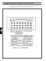
A programming tool, containing a keyboard for user key assignment and a display which shows the
sequence of programming. Mounted in the front panel of the rack unit.
Users of the SM40 Public Address Distribution System are able to program and make changes to the
functions of their system, quickly and easily, with the aid of the Display And Keyboard. This is a simple
programming tool comprising a 24 key keyboard and a 2x40 character lcd display which shows the sequence
of programming.
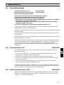
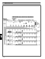
SM40 KEY FUNCTIONS
0-9
Mute
Switches the output, indicated by the cursor,
to the -10 dB mode when it is desired to
attenuate the volume of background music
during an announcement, rather than muting
it.
This function is only available on every fourth
input of the Matrix card.
Break
If pressed during auxiliary programming, will
return user to the main menu for the next
programming sequence (in this case Call
Station programming) without storing any
new information.
During Call Station programming, ‘BREAK’
returns the user to the previous stage in the
program (e.g. after “PROGRAM USER KEY:
(1-10)”, it will go back to “PROGRAM CALL
STATION: (1-16)” without storing any new
information.
Numeric keys to select call station number,
user key number, priority level, attention
signal tone number and program numbers as
listed in the main menu.
Moves the cursor 1 position to the right
when routing Call Stations, Attention Tones,
pre-recorded messages or Auxiliary sources
(background music players, etc.) to amplifier
inputs; each amplifier input representing a
loudspeaker zone. Also used for
programming free-programmable relays.
This is called :
“MATRIX/RELAY PROGRAMMING”.
Moves the cursor 1 position to the left
during matrix/relay programming.
Moves the cursor to the beginning of the
following lock of 8 amplifier inputs during
matrix programming.
Moves the cursor to the end of the previous
block of 8 amplifier inputs during matrix
programming.
1
0
1
0
Enter
Enters numerical inputs into the memory and
moves to the next program stage, or at the
end of a program sequence; to the main
menu ready for the next program.
A
While the system is in its run mode, pressing
button A, displays the system status. The top
line of the display indicates where Call
Stations, Signal Generator Cards, Digital
Message Cards and auxiliary sources are
connected to the matrix. The bottom line
indicates which user key is currently being
pushed, and which SGC is producing a signal
or which DMC is relaying a message.
B
In the Installer programming Menu, button B,
is used to set the I/O RS232 serial interface
communication parameters with an external
computer. The parameters are as follows:
Baud rate, stop bits and parity. See
Chapter 5.13 on the I/O PCB.
C
With the system in programming mode,
button C is used to couple or uncouple the
Keysets (KST)s, as described in the Input
Card, see Chapter 5.3.
Switches the output, indicated by the cursor
during matrix programming, to the “ON”
position. Routing the call station or auxiliary
source being programmed to the desired
amplifier input.
Switches the output to the “OFF” position,
cancelling routing of the call station or
auxiliary to the amplifier input indicated by
the cursor.
Switches all outputs to the “ON” position,
routing the source being programmed to all
amplifier inputs.
Switches all outputs to the “OFF” position,
cancelling all routing of the source being
programmed.
4-3
4
4. OPERATING AND PROGRAMMING THE SM40 SYSTEM
4.3
SM40 Programming
During the remainder of this chapter, specific contexts (status) and user actions are shown in the left
column, and possible display results are shown in the right column. Characters between quotes (‘Key’)
denote keyboard inputs, and ocurrances of XX and YY in any displays shown in the right column denote
information which is dependant on the system configuration, or entered by the user.
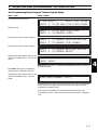
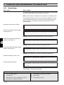
When the SM40 system is powered up, either one of the following two displays is shown:
Status / Action
Result / Remarks
When memory was cleared the display shows:
* * * SYSTEM MUST BE PROGRAMMED * * *
* * *
GO TO INSTALLER MENU
* * *
When the system was installed previously,
the display shows:
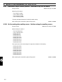
4.3.1
* * * SM40 ROUTING SYSTEM * * *
DAY XX-XX
TIME XX:XX
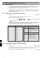
User Programming Menu
The User Programming Menu allows the user to program the following options:
Call Station Programming
-
Call Station No.
Alarm Station No.
User Key No.
Key priority level
Signal No.
Digitally Stored Messages
Unlocked CRC Relay
activation
- Routing to Amplifiers
4
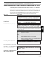
Status / Action
To enter the User Programming Menu, enter
the password: ‘9’, ‘6’, ‘Enter’.
Auxiliary Programming
Real-time clock / timer
settings
(for signals from a music source): - Set real-time clock
- Routing signals to 1 or more - Program timers
outputs
Result / Remarks
>> WELCOME TO SM40 PROGRAMMING MODE <<
>> VERSION X.X
DATE XX-XX-XX <<
Display after entering the password. Indicated here are the software version number
and release date.
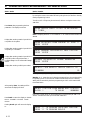
Wait until the welcome message clears.
* USER MENU *
scroll with 'ENTER'
PRESS '1' TO PROGRAM CALL STATIONS
The display now shows the first programming option.
Press ‘Break’ to return the system to its
‘Normal Run Mode’. Otherwise, to proceed
with the first programming option, press the
key marked ‘1’, as shown in the display.
4-4
Note: To scroll through the programming options, use the ‘Enter’ key.
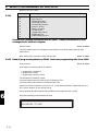
4. OPERATING AND PROGRAMMING THE SM40 SYSTEM
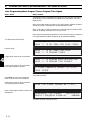
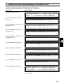
User Programming Menu: Call Station Programming
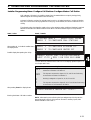
Status / Action
Press the ‘1’ key when the display shows the
‘User Menu’.
Result / Remarks
PROGRAM STATION:_
Enter Call Station number and press ‘Enter’.
When a non-existent Call Station number is
entered (numbers 1-16 in 16x64 mode or 132 in 32x32 mode) the display shows:
Otherwise, when a non-existent Call Station
number was entered (numbers 17-32 in
16x64 mode) the display shows:
Otherwise, when an existing Call Station
number was entered the display shows:
PROGRAM STATION:X
_X
CALL/ALARM STATION XX NOT PRESENT
PROGRAM STATION:X
_X
CALL/ALARM STATION XX NOT PRESENT
PROGRAM STATION:XX
PROGRAM USER-KEY:_
Enter User Key and press ‘Enter’.
4
Pressing ‘Break’ will return display to
“PROGRAM STATION:”.
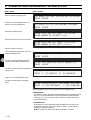
When the Key Number is entered, and the
Call Station number exists the display shows:
Otherwise, when the Key Number is entered
and the Call Station number is between 17
and 32 in 16x64 mode the display shows:
If the current priority level is desired press
‘Enter’ to save this level, otherwise enter the
desired level by pressing one of ‘0’ to ‘9’
followed by ‘Enter’.
CST:XX KEY:XX PRIORITY:X
_ (0-9;0=lowest)
PRESS 'ENTER' OR CHANGE AND PRESS ENTER
AST:XX KEY:XX PRIORITY:X
_ (0-9;0=lowest)
PRESS 'ENTER' OR CHANGE AND PRESS ENTER
The current priority level will blink. If the memory has been cleared previously, the
priority level will be set at default level zero.
Pressing ‘Break’ will return display to
“PROGRAM USER-KEY:”.
If there is a signal generator present within
the system, the display will show:
CST:XX KEY:XX PRIORITY:X SIGNAL NR:X
_X
PRESS 'ENTER' OR CHANGE AND PRESS ENTER
The current signal number programmed for key XX will be displayed. Pressing
‘Enter’ will save this value, any other signal number, followed by ‘Enter’ changes
the signal number. Entering ‘00’ means “no signal”. The list of available signals
should be consulted to avoid selection of a non-existent signal.
4-5
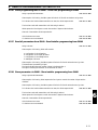
4. OPERATING AND PROGRAMMING THE SM40 SYSTEM
Status / Action
Result / Remarks
When a Modified Surveillance Switch Card
(MSC) installed in the system, used for
activating messages from an external message
source, the display shows:
CST:XX KEY:XX PRIORITY:X
_ SIGNAL NR:XX
MESSAGE:X
The Modified Surveillance Switch Card (MSG) can activate up to 8 messages from
an external message source. Entering ‘0’ means “no message” (default after memory
cleared: zero).
Press ‘Break’ to return to “PROGRAM
USER-KEY:”.
Otherwise, press ‘Enter’. If there are one or
more Digital Message Cards in the system,
the display shows:
CST:XX KEY:XX DMC:X
_X XX XX XX XX XX XX
RECORDED MESSAGES: X X X X X X X
The upper line on the display shows the Digital Message Card selection. The lower
line shows the message numbers.
When activating a call which includes a programmed digital message, all message
cards needed for that call are reserved and can not be used for another call before
the message cycle has ended. This is not the case when the new call has a higher
priority level.
4
Up to 7 individual messages can be randomly programmed under one Call Station
user key. If the selected Digital Message Card is not present, this will be displayed
on the lower display line.
To exit recorded message programming,
enter a ‘0’ for either selection.
Note: Entering a seventh message will also exit message programming.
The selected message will be played sequentially in the same order as programmed.
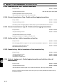
User Programming Menu: Call Station Programming (32x32 mode)
Status / Action
Result / Remarks
The display shows the following:
CST:XX KEY:XX ROUTED TO AMPLIFIERS
00001111 00000*** -------- 11111111
_
01
The above display shows a graphical representation of the routing for key XX of call
station XX. The number of symbol blocks displayed depends on the number of
matrix cards connected to that particular Call Station, or on the presence of
Control Relay Cards L1 to L4.
The number shown at the lower right of the display indicates the actual Amplifier
Zone at the current cursor position.
Keys
,
1,
,
,
0 , ‘Mute’
Move cursor to specific zone
0
1
Zone switched off.
*
Zone switched on (an auxiliary source routed to that
zone will be attenuated during the call). Only possible
for auxiliaries connected to every fourth input.
-
No Matrix Card / Locked Relay Card present.
(De-)activate routing
1
Switch all zones ON
0
Switch all zones OFF
4-6
Symbols
Zone switched on (an auxiliary source routed to that
zone will be muted during the call).
4. OPERATING AND PROGRAMMING THE SM40 SYSTEM
Status / Action
Result / Remarks
When an audio output of SM40 is activated by a call, the corresponding relay of
the Locked Relay Card, with address 1-4 is also automatically activated. If a system
has no more than 8 audio outputs, CRC cards 2, 3 and 4 can be considered as
being freely programmable. However they are still shown on the display as routing.
They can be used to activate zone relays or volume override relays.
Press ‘Enter’ to save the new settings.
Otherwise press ‘Break’ to return to
“PROGRAM USER-KEY:”.
In the 32x32 matrix mode, the relays of Locked Relay Cards L5-L8 are free and can
be considered as free programmable and can be programmed accordingly.
When the routing is entered, the display
shows:
CST:XX KEY:XX ACTIVATES RELAYS (L5-L8):
CST:XX KEY:XX ACTIVATES RELAYS (L5-L8):
11100000 00000000 -------- 00000000
01
_
11100000 00000000 -------- 00000000
01
_
[L-5]
[L-6]
[L-7]
[L-8]
This is the current programming of the relays on Locked Relay Cards 5-8. This
causes the programmed relays to activate when the corresponding Call Station key
is active. In addition the relays on Unlocked CRC U-4, U-5, U-6, U-7 and U-8
can be activated via a user-key.
When ‘Enter’ is pressed and Unlocked CRC
U-4, U-5, U-6, U-7 and U-8 are present in
the system, the display shows:
CST:XX KEY:XX ACTIVATES RELAYS (U4-U8):
00011111 00000000 -------- 00000000
01
_
[U-4]
[U-5]
[U-6]
[U-7]
CST:XX KEY:XX ACTIVATES RELAYS (U4-U8):
00000000
33
_
[U-8]
The above screen shows the current programming of the relays CRC U-4, U-5,
U-6, U-7 and U-8. This causes the programmed relays to activate when the
corresponding Call Station key is active. Programming is identical to matrix
programming.
When the keys of Call Station XX are
programmed, pressing ‘Break’ will return
display to “PROGRAM STATION:”.
When all Call Stations present are
programmed, pressing ‘Break’ again will
return the display to the main menu.
4-7
4
4. OPERATING AND PROGRAMMING THE SM40 SYSTEM
User Programming Menu: Call Station Programming (16x64 mode)
Status / Action
Result / Remarks
The display shows the following:
CST:XX KEY:XX ROUTED TO AMPLIFIERS:
00001111 00000*** -------- 11111111
_
01
The above display shows a graphical representation of the routing for key XX of call
station XX. The number of symbol blocks displayed depends on the number of
matrix cards connected to that particular Call Station, or on the presence of
Control Relay Cards L1 to L8.
The number shown at the lower right of the display indicates the actual Amplifier
Zone at the current cursor position.
Note: A guide to the symbols shown on the display, and to the keys used to edit the
routing, refer to the table on page 4-6.
When an audio output of SM40 is activated by a call, the corresponding relay of
the Locked Relay Card, with address L-1 to L-8 is also automatically activated. If a
system has no more than 8 audio outputs, CRC cards L-2 to L-8 can be considered
as being free programmable. However they are still shown on the display as routing.
They can be used to activate zone relays or volume control override relays.
Press ‘Enter’ to save the new settings.
4
Otherwise, press ‘Break’ to return to
“PROGRAM USER-KEY:”.
When ‘Enter’ is pressed and Unlocked CRC
U-4, U-5, U-6, U-7 and U-8 are present in
the system, the display shows:
CST:XX KEY:XX ACTIVATES RELAYS (U4-U8):
11100000 00000000 00000000 11000001 01
_
[U-4]
[U-5]
[U-6]
[U-7]
CST:XX KEY:XX ACTIVATES RELAYS (U4-U8):
11100000
33
_
[U-8]
The above screen shows the current programming of the relays CRC U-4, U-5,
U-6, U-7 and U-8. This causes the programmed relays to activate when the
corresponding Call Station key is active. Programming is identical to matrix
programming.
When the keys of Call Station XX are
programmed, pressing ‘Break’ will return
display to “PROGRAM STATION:”.
When all Call Stations present are
programmed, pressing ‘Break’ again will
return the display to the main menu.
4-8
4. OPERATING AND PROGRAMMING THE SM40 SYSTEM
User Programming Menu: Auxiliary Programming
Status / Action
Result / Remarks
The display shows the following:
* USER MENU *
scroll with 'ENTER'
PRESS '2' TO PROGRAM AUXILIARIES
Matrix inputs that are not occupied by Call Stations, and are not assigned to Signal
Generators or Message Sources, are available as auxiliary inputs for use with
background music sources etc..
When the ‘2’ key is pressed the system will search for an available matrix input.
When there are no free inputs, the system will skip this program mode.
The ‘2’ key is pressed, and there are free
inputs available. Possible display:
MATRIX INPUT:XX ROUTED TO AMPLIFIERS:
11110000 0000XXXX
01
_
The above display shows the graphical representation of the routing of the auxiliary
source connected to matrix input XX. The number of symbol blocks shown
depends on the number of matrix cards connected to the auxiliary source.
Routing auxiliaries is identical to routing the Call Station, except for the fact that
the ‘Mute’ key is disabled.
When the 1 key is pressed whilst the cursor is positioned at an occupied zone
(marked by an ‘X’), the setting of the previously assigned output will be overridden.
Press ‘Enter’ to save the new settings. The
next free auxiliary input available will be
displayed automatically.
Otherwise, press ‘Break’ to leave settings
unaffected and to return to the Menu User
Menu.
Keys
,
1,
,
0
,
Symbols
Move cursor to specific zone
0
Zone switched off.
Activate routing
1
Zone switched on.
X
Zone already occupied by another auxiliary output.
1
Switch all zones ON
0
Switch all zones OFF
4-9
4
4. OPERATING AND PROGRAMMING THE SM40 SYSTEM
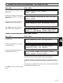
User Programming Menu: Set Real-Time Clock
Status / Action
Result / Remarks
The display shows the following:
* USER MENU *
scroll with 'ENTER'
PRESS '3' TO SET REAL-TIME CLOCK/TIMERS
Press the ‘3’ key.
PRESS '1' TO SET REAL-TIME CLOCK
PRESS '2' TO PROGRAM TIMERS
When the ‘1’ key is pressed the display shows:
ENTER
DD-MM HH:MM
XX-XX XX:XX
_
The current time will be displayed and the cursor will blink at the tens of ‘DD’. The
date and time settings can be changed by either entering the complete date and
time, or by moving the cursor to a position to change a single value.
Press ‘Enter’ to save the new setting.
When ‘Enter’ is pressed and the date and
time values are valid, the display shows:
4
Enter the last two numbers of the
current year.
Press ‘Break’ to return to the Menu User
Menu without changing the date and/or time
settings.
Otherwise press ‘Enter’ to store the setting
and return to the Menu User Menu.
4-10
When an invalid time and/or date is entered, this is shown by marking the
incorrect value with a question mark (‘?’).
ENTER LAST 2 DIGITS OF CURRENT YEAR _
XX
The SM40 system will now calculate the current day-of-the-week.
4. OPERATING AND PROGRAMMING THE SM40 SYSTEM
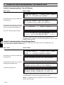
User Programming Menu: Program Timers: Program Auxiliary Routing
Status / Action
Result / Remarks
The display shows the following:
* USER MENU *
scroll with 'ENTER'
PRESS '3' TO SET REAL-TIME CLOCK/TIMERS
Press the ‘3’ key.
PRESS '1' TO SET REAL-TIME CLOCK
PRESS '2' TO PROGRAM TIMERS
Display shown when the ‘2’ key is pressed.
PRESS '1' TO PROGRAM RELAY/AUX-ROUTING
PRESS '2' TO PROGRAM TIME SIGNALS
Display shown when the ‘1’ key is pressed.
PRESS '1' TO PROGRAM AUXILIARY ROUTING
PRESS '2' TO PROGRAM RELAYS
Display shown after pressing the ‘1’ key, and
when Unlocked Relay Card 2 is not in the
system.
*WARNING* UNLOCKED CRC #2 NOT IN SYSTEM
PRESS 'ENTER'
Note: Because this Matrix Timer mode is intended for supplying background music
to several zones at several times, the use of a relay contact is not always required.
The display shown above is intended as a warning and not as a fatal error message.
Press ‘Enter’ when the warning was shown,
otherwise press ‘1’.
When Unlocked CRC U-2 is present the
display shows:
ENTER RELAY NUMBER (1-8):_
When Unlocked CRC U-2 is not present the
display shows:
ENTER TIMER GROUP (1-8):_
Enter the relay/group number.
RELAY: X ACTIVE FROM _
00:00 DAY: MTWTFSS
BLOCK: 0
TO 00:00
0000000
Note: The word ‘RELAY’ shown above will be replaced by ‘GROUP’ when
Unlocked CRC U-2 is not present.
The cursor will flash at the tens of the ‘ACTIVE FROM’ time. Use the cursor keys
to position the cursor, and the number keys to alter values. Use the double arrow
keys to move to the next or previous block.
4-11
4
4. OPERATING AND PROGRAMMING THE SM40 SYSTEM
Status / Action
Result / Remarks
The week-field is intended to set a day of the week active or inactive. This is done
by moving the cursor to the week-field and by using the On/Off similar to the way
matrix programming is done.
The All-On/All--Off keys may be used as well, without moving the cursor to the
week-field.
Press ‘Enter’ after programming the time
parameters. The display now shows:
ENTER MATRIX INPUT (1-16) TO BE ROUTED
BY TIMER:_
Note: The display will show ‘1-32’ instead of ‘1-16’ when the 32x32 Matrix was
selected.
Display after entering a matrix input which is
not present in the system:
Display after entering a matrix input which is
occupied by a Call Station:
4
Display after entering a matrix input which is
occupied by either a Signal Generator, a
Digital Message Card of an External Message
Source:
ERROR NO MATRIX CARD PRESENT AT INPUT X
PRESS 'ENTER'
INPUT ALREADY OCCUPIED BY CALL STATION
PRESS 'ENTER'
ALREADY OCCUPIED BY SIGNAL GENERATOR
PRESS 'ENTER'
Display after entering a valid input number:
RELAY:X TIME BLOCK:_ MATRIX INPUT:_ TO
XXX00000
01
_
Auxiliary Routing Programming is identical to Auxiliary Programming.
Warning: An ‘X’ means the zone is already programmed from the normal Auxiliary
Programming mode. If the timer also needs to activate these zones, the auxiliary
setting will be overruled by the timer programming and will not be restored after
timer deactivation.
After pressing ‘Enter’, the settings will be
stored and the display will show:
RELAY: X ACTIVE FROM _
00:00 DAY: MTWTFSS
BLOCK: 1
TO 00:00
0000000
Every relay or timer group can be programmed in 10 time blocks per week. The
‘BLOCK’ number will count up to 9 and then restart at 0.
Press ‘Break’ to return the display to ‘ENTER
RELAY NUMBER’ or ‘ENTER TIMER
GROUP’.
Pressing ‘Break’ again will return the display
to:
4-12
PRESS '1' TO PROGRAM AUXILIARY ROUTING
PRESS '2' TO PROGRAM RELAYS
4. OPERATING AND PROGRAMMING THE SM40 SYSTEM
User Programming Menu: Program Timers: Program Relays
Status / Action
Result / Remarks
The display shows the following:
* USER MENU *
scroll with 'ENTER'
PRESS '3' TO SET REAL-TIME CLOCK/TIMERS
Press the ‘3’ key.
PRESS '1' TO SET REAL-TIME CLOCK
PRESS '2' TO PROGRAM TIMERS
Display shown when the ‘2’ key is pressed.
PRESS '1' TO PROGRAM RELAY/AUX-ROUTING
PRESS '2' TO PROGRAM TIME SIGNALS
Display shown when the ‘1’ key is pressed.
PRESS '1' TO PROGRAM AUXILIARY ROUTING
PRESS '2' TO PROGRAM RELAYS
Display shown after pressing the ‘2’ key, and
when Unlocked Relay Card U-3 is not in the
system.
**ERROR** UNLOCKED CRC3 NOT IN SYSTEM
PRESS 'ENTER'
Note: Because card CRC U-3 is required for this particular function, this error is of
the class ‘Fatal Error’.
Press ‘Enter’ when the error message was
shown to return to the Main User Menu.
Display shown after pressing the ‘2’ key, and
when Unlocked Relay Card U-3 is in the
system.
ENTER RELAY NUMBER (1-8):_
Programming relays is similar to programming the matrix timers, except that after
entering the time, the display returns with the next relay-program instead of
programming the matrix routing.
Every relay can be programmed to activate and de-activate 10 times a day.
Unlocked Relay Card U-3 has 8 relays, therefore the total number of relay timers
is 80.
4-13
4
4. OPERATING AND PROGRAMMING THE SM40 SYSTEM
User Programming Menu: Program Timers: Program Time Signals
Status / Action
Result / Remarks
Time Signals (30 max.) are treated by the system as ‘Calls’, with their own priority
(set at priority 0). This means that a time signal can be overruled by a call with a
higher priority.
When a time signal activates, and there is no Signal Generator available, the system
will wait until there is a free generator and then generate the signal.
When a Call Station is calling the same zone to which the signal is routed, the time
signal will be delayed until there is no more zone conflict.
When several time signals are programmed to sound at the same time, and there are
not enough generators available, the signals will be activated sequentially.
The display shows the following:
* USER MENU *
scroll with 'ENTER'
PRESS '3' TO SET REAL-TIME CLOCK/TIMERS
Press the ‘3’ key.
PRESS '1' TO SET REAL-TIME CLOCK
PRESS '2' TO PROGRAM TIMERS
Display shown when the ‘2’ key is pressed.
4
PRESS '1' TO PROGRAM RELAY/AUX-ROUTING
PRESS '2' TO PROGRAM TIME SIGNALS
Display shown when the ‘2’ key is pressed.
but no signal generator is present:
NO SIGNAL GENERATOR PRESENT IN SYSTEM
PRESS 'ENTER'
Note: Because a signal generator is required for this particular function, this error is
of the class ‘Fatal Error’.
Press ‘Enter’ when the error message was
shown to return to the Main User Menu.
Display shown when the ‘2’ key is pressed.
and a signal generator is present:
ENTER TIME SIGNAL PROGRAM NR (1-30):_
When a valid program number is entered, the
display shows:
PROGRAMMING TIME SIGNALS
PRGM:XX TIME:0
_0:00 SIGNAL:XX
The cursor will blink at the tens of hours.
4-14
DAYS:MTWTFSS
0000000
4. OPERATING AND PROGRAMMING THE SM40 SYSTEM
Status / Action
Result / Remarks
Enter the time and day at which the signal
must sound.
The time can be set using the numeric keyboard. This way a signal will sound only
at that particular time on the day it was set. It is also possible to use ‘don’t care’
values using the ‘Mute’ key.
For example:
- Time set at ‘**:00’,
- The signal will sound on the hour, 24 times a day.
- Time set at ‘0*:30’,
- The signal will sound from 00:00 to 09:59 on the half hour.
- Time set at ‘**:**’,
- The signal will sound every minute.
The display shows the following:
Every signal available in the Signal Generator may be selected, except for signals
with a number of 57 or higher (alarm signals).
Programming the week-field is identical to matrix & relay timer setting.
Display after pressing ‘Enter’, if the Signal
Generator is not yet routed.
*WARNING* SIGNAL GENERATOR NOT ROUTED
PRESS 'ENTER'
Note: This is a ‘Fatal Error’ message, and after pressing ‘Enter’, the display will
return to the Main User Menu.
Press ‘Enter’ to save the settings.
When a Digital Message Card is installed in
the system, the display now shows:
Illegal time inputs and no signal number set, when any day was set active will not
be accepted by the system. In this case the time set display will not disappear, and
the cursor will blink at the illegal input.
PROGRAM:01
DMC:00 00 00 00 00 00 00
RECORDED MESSAGES: 0 0 0 0 0 0 0
Every ‘Time Signal’ can activate up to seven messages from one or more Digital
Message Cards. Programming is identical to Call Station Programming.
Otherwise, when a Digital Message Card is
not installed in the system, the display will
now show:
PROGRAM:01
DMC:0X 00 00 00 00 00 00
SELECTED DMC NOT PRESENT: PRESS 'ENTER'
Display after selection of Digital Messages
Press ‘Enter’ to show the next time signal
process.
PROGRAM:XX SWITCHES SIGNAL:XX TO AMPL:
00000000 00000000 00000000 00000000
01
_
Note: The fourth input of each Matrix Card can be attenuated during a time signal
instead of being muted (using the ‘Mute’ key).
4-15
4
4. OPERATING AND PROGRAMMING THE SM40 SYSTEM
User Programming Menu: Leaving the User Programming Menu
Status / Action
Press ‘Break’ as often as necessary to return to
the Main User Menu:
Press ‘Enter’ to return to the first option of
the Main User Menu:
Otherwise press ‘Break’ once more to return
to ‘Normal Run Mode’.
Result / Remarks
* USER MENU *
scroll with 'ENTER'
PRESS 'BREAK' TO EXIT PROGRAMMING MODE
* USER MENU *
scroll with 'ENTER'
PRESS '1' TO PROGRAM CALL STATIONS
* * * SM40 ROUTING SYSTEM * * *
DAY XX-XX
TIME XX:XX
Notes:
- ‘DAY’ shown on the display above will be replaced by either one of ‘MON’, ‘TUE’,
‘WED’, ‘THU’, ‘FRI’, ‘SAT’, ‘SUN’.
- It is not necessary to scroll the Main User Menu to a specific option to be able to
select it. For instance, option ‘3’ can be selected by pressing the ‘3’ key, even
though the display shows ‘PRESS '1' TO PROGRAM CALL STATIONS’.
4
4-16
4. OPERATING AND PROGRAMMING THE SM40 SYSTEM
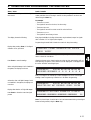
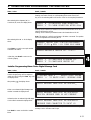
4.3.2
Error Messages
Status / Action
Result / Remarks
The SM40 system continuously monitors to see whether all cards and Call Stations
are still connected and communicating with the CPC. If, for some reason, a card is
not communicating with the CPC; a Call Station is disconnected or a Call station’s
detection current exceeds the limit, one of the following messages will be displayed.
Note: These messages will not be displayed when them SM40 system is in
programming mode or in status display mode.
* * * * ERROR * * * *
CALL/ALARM STATION XX
* * * * ERROR * * * *
INPUT CARD XX
* * * * ERROR * * * *
MATRIX CARD XX
4
* * * * ERROR * * * *
GENERATOR CARD XX
* * * * ERROR * * * *
LOCKED CONTROL RELAY CARD XX
* * * * ERROR * * * *
UNLOCKED CONTROL RELAY CARD XX
* * * * ERROR * * * *
MESSAGE SWITCH CARD XX
* * * * ERROR * * * *
DIGITAL MESSAGE CARD XX
4-17
4. OPERATING AND PROGRAMMING THE SM40 SYSTEM
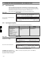
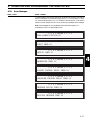
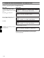
4.3.3
Status Display
Status / Action
Result / Remarks
The SM40 system is able to display its static and dynamic state. Switching between
the normal and status display is done by means of the ‘A’ key.
Note: The status display is unavailable when the system is in programming mode.
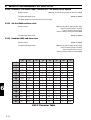
The status displays upper line shows 4 blocks containing 4 symbols each. These
symbols represent the inputs (1-16) of the matrix cards. Pressing ‘A’ again shows
inputs 17-32. When ‘A’ is pressed once again, the system returns to normal
time/date display.
Status shown when memory is cleared:
Possible status display after storing system
hardware (option 4):
- - - -
- - - -
- - - -
- - - -
C C - -
C - - -
- - - -
- - - -
Meaning: Call Stations are connected to inputs 1, 2 and 5 of the matrix.
Possible status display after programming
auxiliary sources (option 2):
4
C C - X
C - - X
- - - -
- - - -
Meaning: Auxiliary sources are connected to matrix input 4 and 8.
Possible status display after assigning signal
generator input (option 6):
C C G X
C - - X
- - - -
- - - -
Meaning: A signal generator is (or must be) connected to matrix input 3.
Possible status display of inputs 17-32:
K K K -
S S S S
A A - -
- - - -
C C G X
C - - X
- - - -
- - - -
Possible dynamic status display:
4 *
Meaning: Call Station 2 is active, and the ‘4’ key was pressed. Furthermore, the
Signal Generator (3) produces the calls signal.
Symbol Guide
C
X
G
K
Call or activating station
Auxiliary input
Signal generator input or Message source input
Key Station for extended Call Station
4-18
S
A
-
Selected station for Master Call Station
Alarm Station
Not assigned or present
4. OPERATING AND PROGRAMMING THE SM40 SYSTEM
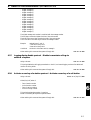
4.3.4
Installer Programming Menu
The Installer Programming Menu allows the user to program the following options:
-
Store System Hardware
Key: ‘4’
Show System Hardware
Key: ‘5’
Call Stations connected
Alarm Stations connected
Key Stations connected
Selection Stations connected
PC inputs assigned
Routing Signal Generator
-
Input card(s)
Matrix card(s) 16 inputs
Matrix card(s) 32 inputs
Signal generator(s)
Message switch card(s)
-
Digital Message card(s)
Locked CRC(s)
Unlocked CRC(s)
Serial I/O
Communication PCB
Key: ‘6’
- Routing Signal Generator
- Routing to Matrix input
Manual Signal Selection
(for monitoring signals)
Key: ‘7’
- Generator No..
- Signal No..
Clear All Memory
Key: ‘8’
Route Message Source
Key: ‘9’
4
- Message source
- Message card
Set Matrix Configuration
Key: ‘0’
Select Program
Shut-Off timer
Key: ‘A’
- Disable/Enable
- Time between last key-stroke
Setup I/O Parameters
Key: ‘B’
Configure Call Stations
Key: ‘C’
- Configure Extended CST
- Configure master CST
Route Digital Message Card
Message (Re-)Recording
Message Monitoring
Message Card Back-Up
Exit Programming Mode
- Separate / combine
- Couple / Uncouple
Key: ‘
’
Key: ‘ ’
Key: ‘
Key: ‘
’
Key: ‘Break’
4-19
4. OPERATING AND PROGRAMMING THE SM40 SYSTEM
Status / Action
To enter the Installer Menu, enter the
password: ‘8’, ‘1’, ‘Enter’.
Result / Remarks
>> WELCOME TO SM40 PROGRAMMING MODE <<
>> VERSION X.X
DATE XX-XX-XX <<
Display after entering the password. Indicated here are the software version number
and release date.
Wait until the welcome message clears. The
display now shows:
* INSTALL MENU *
scroll with 'ENTER'
PRESS '4' TO STORE SYSTEM HARDWARE
Note: Options 1, 2 and 3 are identical to modes 1, 2 and 3 of the User
Programming Menu.
Note: To scroll through the programming options, use the ‘Enter’ key. Use the
‘Break’ key to abort a command without storing information.
Press ‘4’ to store hardware configuration.
4
* INSTALL MENU *
scroll with 'ENTER'
STORING HARDWARE CONFIGURATION....
Storing hardware information is necessary to enable dynamic system error
detection.
Press ‘Enter’ in the Installer Menu to show
option 0:
* INSTALL MENU *
scroll with 'ENTER'
PRESS '0' TO SET MATRIX CONFIGURATION
To enable systems with more than 16 audio inputs, it is possible to choose between
16 inputs with 64 outputs, and 32 inputs with 32 outputs. The latter is the
maximum input configuration.
Press ‘0’ to select the matrix configuration
option. The current situation is shown being
either:
CURRENT MATRIX: 16 INPUTS; 64 OUTPUTS
PRESS '0' FOR 16X64; '1' FOR 32X32
Or:
CURRENT MATRIX: 32 INPUTS; 32 OUTPUTS
PRESS '0' FOR 16X64; '1' FOR 32X32
Press ‘0’ or ‘1’ to select a matrix configuration
or press ‘Break’ to leave this setting
untouched.
4-20
4. OPERATING AND PROGRAMMING THE SM40 SYSTEM
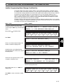
Installer Programming Menu: Display System Hardware
Status / Action
Result / Remarks
The display shows the following:
* INSTALL MENU *
scroll with 'ENTER'
PRESS '5' TO DISPLAY SYSTEM HARDWARE
Press ‘5’, and the display shows (for Call
Stations 1-16):
CALL STATIONS CONNECTED: XX, XX, XX
After pressing ‘Enter’ the display shows (for
Call Stations 17-32):
CALL STATIONS CONNECTED: XX, XX, XX
After pressing ‘Enter’ the display shows (for
Alarm Stations 1-16):
ALARM STATIONS CONNECTED: XX, XX, XX
After pressing ‘Enter’ the display shows (for
Alarm Stations 17-32):
ALARM STATIONS CONNECTED: XX, XX, XX
4
After pressing ‘Enter’ the display shows:
KEY STATIONS CONNECTED: XX, XX, XX
After pressing ‘Enter’ the display shows:
SELECT. STATIONS CONNECTED: XX, XX, XX
After pressing ‘Enter’ the display shows:
PC INPUTS ASSIGNED: XX, XX, XX
After pressing ‘Enter’ the display shows:
INPUT CARD(S) NR: XX, XX, XX
After pressing ‘Enter’ the display shows:
MATRIX CARD(S):
(16 inputs)
I-XXXXXXXX XXXXXXXX
II-XXXXXXXX XXXXXXXX
Note: When the 32x32 matrix has been selected, ‘16’ will be replaced by ‘32’ on
the above display.
4-21
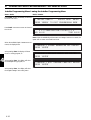
4. OPERATING AND PROGRAMMING THE SM40 SYSTEM
Status / Action
Result / Remarks
After pressing ‘Enter’ the display shows:
SIGNAL GENERATOR(S) NR: XX, XX, XX
After pressing ‘Enter’ the display shows:
MESSAGE SWITCH CARD(S) CONNECTED: XX, XX
After pressing ‘Enter’ the display shows:
DIGITAL MESSAGE CARD(S): XX, XX
After pressing ‘Enter’ the display shows:
LOCKED CRC(S): XX, XX, XX
UNLOCKED CRC(S): XX, XX, XX
After pressing ‘Enter’ the display shows:
I/O BOARD MOUNTED: YES
After pressing ‘Enter’ the display shows:
4
* INSTALL MENU *
scroll with 'ENTER'
PRESS '6' TO ROUTE SIGNAL GENERATOR
Installer Programming Menu: Routing Signal Generator
Status / Action
After pressing ‘6’ in the Main Installer Menu
the display shows:
When the selected generator is not present,
the display will show:
Otherwise, when the selected generator is
present the display will show:
Result / Remarks
WHICH GENERATOR MUST BE ROUTED (1-8):_
WHICH GENERATOR MUST BE ROUTED (1-8):X
_
GENERATOR CARD X NOT PRESENT
WHICH GENERATOR MUST BE ROUTED (1-8):X
SIGNAL GENERATOR CONNECTED TO INPUT:X
_X
The current matrix input number is displayed, unless memory was cleared in which
case2 black squares are displayed. The input to which the generator is routed
depends on the matrix configuration.
Press ‘Enter’ to store the changed input
number , or ‘Break’ to return to the Main
Installer Menu.
4-22
4. OPERATING AND PROGRAMMING THE SM40 SYSTEM
Status / Action
When ‘Enter’ was pressed but there is no
matrix card present at the selected input the
display shows:
Otherwise, when assigning a matrix input
that is already occupied by a Call Station the
display shows:
Otherwise, when the input is accepted the
display will ask for the next routing:
When ‘Break’ is pressed, the display will
again show the Main Installer Menu:
Result / Remarks
MATRIX INPUT XX NOT PRESENT
PRESS 'ENTER'
INPUT ALREADY OCCUPIED BY CALL STATION
PRESS 'ENTER'
WHICH GENERATOR MUST BE ROUTED (1-8):_
* INSTALL MENU *
scroll with 'ENTER'
PRESS '7' FOR MANUAL SIGNAL SELECTION
Installer Programming Menu: Manual Signal Selection
Status / Action
After pressing ‘7’ in the Main Installer Menu
the display shows:
When the selected generator is not present,
the display will show:
Otherwise, when the selected generator is
present the display will show:
Result / Remarks
WHICH GENERATOR MUST BE MONITORED:_
4
WHICH GENERATOR MUST BE MONITORED:X
_
GENERATOR CARD X NOT PRESENT
TYPE SIGNAL NUMBER AND PRESS 'ENTER'
PRESS 'ENTER' TO END SIGNAL
Entering a signal number followed by ‘Enter’ will activate the selected generator.
Pressing ‘Enter’ without entering a signal number will end the signal.
Because calls have priority over generator monitoring, it is possible that during
monitoring, a monitored signal will be overridden by a signal which precedes that
call.
When monitoring a generator which is being used for a call, the selected signal will
be available when the generator is free.
Press ‘Break’ to return to the Main Installer
Menu.
4-23
4. OPERATING AND PROGRAMMING THE SM40 SYSTEM
Installer Programming Menu: Clear All Memory
Status / Action
Result / Remarks
* INSTALL MENU *
scroll with 'ENTER'
PRESS '8' TO CLEAR ALL MEMORY
After pressing ‘8’ in the Main Installer Menu
the display shows:
All keys except the ‘0’ will return to the Main
Installer Menu. After pressing the ‘0’ key the
memory is cleared and the display shows:
CLEAR ALL MEMORY: ARE YOU SURE???
'0' clears: any other key aborts
* * * WARNING
MEMORY CLEARED * * *
After a short delay the display changes to:
* * * SYSTEM MUST BE PROGRAMMED * * *
* * *
GO TO INSTALLER MENU
* * *
As a result of clearing the memory, the system will be inoperative until it is
reprogrammed. It is necessary to re-enter the installer password in order to enter the
Installer Programming mode.
4
Installer Programming Menu: Route Message Source
This function is to route external message sources which are activated by a surveillance switch card (message switch card).
Clock synchronisation is available, see section 5.10.
Status / Action
Result / Remarks
* INSTALL MENU *
scroll with 'ENTER'
PRESS '9' TO ROUTE MESSAGE SOURCE
After pressing ‘9’ in the Main Installer Menu
the display shows:
After entering the number of a non-existent
message source the display shows:
WHICH MESSAGE SOURCE MUST BE ROUTED:_
WHICH MESSAGE SOURCE MUST BE ROUTED:X
_X
MESSAGE SWITCH CARD XX NOT PRESENT
Otherwise, the display shows:
WHICH MESSAGE SOURCE MUST BE ROUTED: XX
MESSAGE SOURCE CONNECTED TO INPUT XX
The display shows the current routing. The input to which a message source can be
connected depends on the matrix configuration (16x64 or 32x32).
NOTE: If a surveillance switch card is applied for clock synchronisation only, the
selected input must be 0/0/.
4-24
4. OPERATING AND PROGRAMMING THE SM40 SYSTEM
Installer Programming Menu: Select Program Shut-Off Timer
Status / Action
Result / Remarks
* INSTALL MENU *
scroll with 'ENTER'
PRESS 'A' TO SELECT PRGM SHUT-OFF TIMER
This option is used to enable or disable automatic return to the normal running
mode from the programming mode after a pre-programmed idle delay from 2 to 9
minutes. The idle timer is reset every time a keystroke is detected.When the delay
time has elapsed, the system will drop out of the Installer Programming mode and
return to the normal run mode.
After pressing ‘A’ in the Main Installer Menu
the display shows:
PROGRAMMING MODE SHUT-OFF TIMER
PRESS '0' TO DISABLE; '1' TO ENABLE
The system will wait for keyboard input. During this period the shut-off timer is
temporarily disabled (if it was enabled previously).
Press ‘Break’ to return to the Main Installer
Menu without changing the setting.
Otherwise press ‘0’ to disable the Shut-Off
timer and return to the Main Installer Menu.
4
Otherwise press ‘1’ to enter the delay time:
ENTER TIME (2-9 MINUTES) BETWEEN
LAST KEYSTROKE AND SHUT-OFF
Press any key of ‘1’ to ‘9’ to set the delay
time, or press ‘Break’ to return to the Main
Installer Menu leaving the setting untouched.
Note: Unless and Signal Generator Card (SGC), Digital Message Card (DMC) or
Surveillance Switch Card (SSC) is installed in the system, the Select Program ShutOff Timer is the last programming option.
4-25
4. OPERATING AND PROGRAMMING THE SM40 SYSTEM
Installer Programming Menu: Set-Up I/O Parameters
Status / Action
To set-up Input/Output (I/O) parameters
enter the Installer Programming menu as
explained earlier, and scroll (using the ‘Enter’
key) until the display shows:
Result / Remarks
* INSTALL MENU *
scroll with 'ENTER'
PRESS 'B' TO SET I/O PARAMETERS
Note: The I/O parameters can only be set-up when the I/O PCB LBB 1375 is
mounted on the CPC.
After pressing ‘B’ in the Main Installer Menu
the display shows:
PRESS BREAK TO DISABLE I/O
PRESS 'ENTER' TO PROCEED
Press ‘Break’ to return to the Main Installer
Menu without changing the settings.
Otherwise press ‘Enter’:
SELECT BAUD RATE:_
1:300 2:1200 3:2400
4:4800
5:9600
Select the desired baud-rate and press ‘Enter’:
SELECT NUMBER OF STOP BITS (1 or 2):_
Select the desired number of stop-bits (‘1’ or
‘2’) and press ‘Enter’:
PARITY SELECTION:_
1:EVEN 2:ODD 3:NO PARITY
Select the required parity setting and press
‘Enter’:
* INSTALL MENU *
scroll with 'ENTER'
PRESS 'C' TO CONFIGURE CALL STATIONS
4
4-26
4. OPERATING AND PROGRAMMING THE SM40 SYSTEM
Installer Programming Menu: Configure Call Stations: Configure Extended Call Station
The Extended Call Station programming option makes it possible to configure 1 to 4 Call Stations with
more than 10 keys.
The (key-) stations connected to input cards 5, 6, 7 and 8 can be coupled to Call Stations 1, 2, 3 or 4 but
the total number of assigned key sets (including the Master Call Stations) can never exceed 16 (160 keys).
Every (key-) station of the coupled key sets behaves like a normal Call Station. A hardware addition is
necessary when the LED indicators of the Call Stations and Key Stations need to be coupled.
Status / Action
Result / Remarks
* INSTALL MENU *
scroll with 'ENTER'
PRESS 'C' TO CONFIGURE CALL STATIONS
After pressing ‘C’ in the Main Installer Menu
the display shows:
PRESS '1' TO CONFIGURE EXTENDED CST
PRESS '2' TO CONFIGURE MASTER CST
Possible display after pressing the ‘1’ key:
CURRENT EXTENDED CALL STATION ASSIGNMENT
INPUT 17-32
ECS: 1110 2220 XXXX 0000
The four blocks of characters at the lower line on the display represent inputs 17 to
32 of input cards 5 to 8.
Explanation
111
The key sets connected to inputs 17, 18 and 19 are functioning as
extensions of Call Station 1.
222
The key sets connected to inputs 21, 22, and 23 are functioning
as extensions of Call Station 2.
0
Nothing is assigned to inputs 24, 29, 30, 31 and 32.
X
The key sets connected to inputs25, 26, 27 and 28 are functioning
as extensions of the Master Call Station.
After pressing ‘Enter’ the display shows:
COUPLE/UNCOUPLE EXTENDED CST (1-4):_
Entering the Extended Call Station number.
If the number of a non present Extended Call
Station is entered the display shows:
Otherwise, when the selected Extended Call
Station is in use the display shows:
*** ERROR *** CALL STATION NOT IN SYSTEM
PRESS 'ENTER'
*** ERROR *** STATION ALREADY ASSIGNED
PRESS 'ENTER'
4-27
4
4. OPERATING AND PROGRAMMING THE SM40 SYSTEM
Status / Action
Otherwise, the display shows:
Enter the first of the range of key set inputs:
xx =17,21,25, 29 for master 1,2,3,4.
Enter the number of key sets.
If the corresponding slave Input Card is not
present the display shows:
Otherwise, when the required number of
inputs is not available the display shows:
Result / Remarks
ENTER FIRST KEY SET INPUT (17-32):XX
ENTER NUMBER OF KEYSETS (1-4)
*** ERROR *** INPUT CARD X NOT PRESENT
PRESS 'ENTER'
** NOT ALL SELECTED INPUTS PRESENT **
PRESS 'ENTER'
PRESS '1' TO COUPLE; '0' TO UNCOUPLE
Otherwise, when the inputs are accepted the
display shows:
Selecting ‘1’ will couple the selected range of key set inputs, ‘0’ will uncouple the
selected range.
4
After pressing either ‘1’ or ‘0’, the display
shows:
CURRENT EXTENDED CALL STATION ASSIGNMENT
INPUT 17-32
ECS: 1110 2220 XXXX 0000
COUPLE/UNCOUPLE EXTENDED CST (1-4):_
Press ‘Enter’ to couple or uncouple another
Extended Call Station:
Otherwise, press ‘Break’ to return to the
following display:
4-28
PRESS '1' TO CONFIGURE EXTENDED CST
PRESS '2' TO CONFIGURE MASTER CST
4. OPERATING AND PROGRAMMING THE SM40 SYSTEM
Installer Programming Menu: Configure Call Stations: Configure Master Call Station
With a Master Call Station it is possible to depart from the standard SM40 concept by having priority,
attention signals and routing hidden under one user key.
A Master Call Station consists of an activation section and 1 to 16 selection stations. A number of selection
keys (one or more zones can be programmed for every key) can be selected, and will be combined into one
routing.
The selected routing is activated by pressing a key on the activation station. Additional hardware is required
between the activation and selection stations to be able to indicate the selected keys from every selection
station.
Status / Action
Result / Remarks
* INSTALL MENU *
scroll with 'ENTER'
PRESS 'C' TO CONFIGURE CALL STATIONS
After pressing ‘C’ in the Main Installer Menu
the display shows:
PRESS '1' TO CONFIGURE EXTENDED CST
PRESS '2' TO CONFIGURE MASTER CST
Possible display after pressing the ‘2’ key:
CURRENT MASTER CALL STATION ASSIGNMENT
INPUT 17-32
ECS: 1110 2220 XXXX 0000
The four blocks of characters at the lower line on the display represent inputs 17 to
32 of input cards 5 to 8.
Explanation
111
The key sets connected to inputs 17, 18 and 19 are functioning as
extensions of Master Call Station 1.
222
The key sets connected to inputs 21, 22, and 23 are functioning
as extensions of Master Call Station 2.
0
Nothing is assigned to inputs 24, 29, 30, 31 and 32.
X
The key sets connected to inputs25, 26, 27 and 28 are functioning
as extensions of an Extended Call Station.
After pressing ‘Enter’ the display shows:
COUPLE/UNCOUPLE MASTER CST (1-4):_
Entering the Master Call Station number.
NOTE: After entering and confirming the input assignments of the key sets, the
appropriate audio inputs of the key sets can be used for auxiliary inputs, these
become available in menu item 2.
4-29
4
4. OPERATING AND PROGRAMMING THE SM40 SYSTEM
Status / Action
If the number of a non present Master Call
Station is entered the display shows:
Otherwise, when the selected Master Call
Station is in use the display shows:
Result / Remarks
*** ERROR *** CALL STATION NOT IN SYSTEM
PRESS 'ENTER'
*** ERROR *** STATION ALREADY ASSIGNED
PRESS 'ENTER'
Otherwise, the display shows:
ENTER FIRST KEY SET INPUT (17-32):XX
ENTER NUMBER OF KEYSETS (1-4)
Enter the first of the range of key set inputs:
ENTER FIRST KEY SET INPUT (17-32):XX
ENTER NUMBER OF KEY SETS (1-16):_
Enter the number of key sets.
If the corresponding slave Input Card is not
present the display shows:
4
Otherwise, when the required number of
inputs is not available the display shows:
Otherwise, when the inputs are accepted the
display shows:
*** ERROR *** INPUT CARD X NOT PRESENT
PRESS 'ENTER'
** NOT ALL SELECTED INPUTS PRESENT **
PRESS 'ENTER'
MASTER: X
KEYSETS: XX XX
PRESS '1' TO COUPLE; '0' TO UNCOUPLE
Press ‘0’ to uncouple the selected range.
Otherwise, after pressing ‘1’ the display
shows:
ENTER SIGNAL/PRIORITY PRE-SELECTION MODE
PRESS '0' FOR SEPARATE; '1' FOR COMBINED
Activating selected routing can be programmed in two separate modes:
0 Separate Mode
Five attention or alarm signals plus Digital Messages can be programmed under
keys 1 to 5 of the activation station Four priority levels can be programmed
under keys 6 to 9 of the activation station. Keys 6 to 9 will also activate the
complete pre-selection.
1 Combined Mode
Nine attention or alarm signals plus Digital Messages with a priority can be
programmed under keys 1 to 9 of the activation station. The keys will also
activate the complete pre-selection.
Note: This selection is valid for each Master Call Station connected.
4-30
4. OPERATING AND PROGRAMMING THE SM40 SYSTEM
Status / Action
Result / Remarks
Note: The keys of the selection station have a toggle function for route selection.
Pressing once means ‘Zone(s) on’ whilst pressing twice means ‘Zone(s) off ’.
Key 10 of the activating station will act as a ‘Clear’ for the complete pre-selection.
After selecting either Separate (‘0’) or
Combined (‘1’) mode, the display shows:
PRESS '0' TO MAINTAIN ZONE SELECTION
PRESS '1' TO CLEAR SELECTION AFTER CALL
Pressing ‘0’ will cause the pre-selected zone to be maintained after end of call; the
reset key will clear the routing.
Pressing ‘1’ will cause the pre-selected zones to be cleared after end of call.
Note: This selection is valid for each Master Call Station connected. The question
will not be repeated at the following MCSs.
After selecting either ‘0’ or ‘1’ the display
shows:
Press ‘Enter’ to couple or uncouple another
Extended Call Station:
Otherwise, press ‘Break’ to return to the
following display:
CURRENT MASTER CALL STATION ASSIGNMENT
INPUT 17-32
MCS: 1111 2200 XXXX 0000
COUPLE/UNCOUPLE MASTER CST (1-4):_
4
PRESS '1' TO CONFIGURE EXTENDED CST
PRESS '2' TO CONFIGURE MASTER CST
Installer Programming Menu: Route Digital Message Card
Status / Action
Result / Remarks
To route the Digital Message Card enter the
Installer Programming menu as explained
earlier, and scroll (using the ‘Enter’ key) until
the display shows:
After pressing ‘
* INSTALL MENU *
scroll with 'ENTER'
PRESS '<<' TO ROUTE DIGIT. MESSAGE CARD
’ the display shows:
WHICH MESSAGE CARD MUST BE ROUTED:_
When a non-existent Digital Message Card
number is entered the display shows:
Otherwise, when an existent Digital Message
Card number is entered the display shows:
WHICH MESSAGE CARD MUST BE ROUTED:X
_X
DIGITAL MESSAGE CARD XX NOT PRESENT
WHICH MESSAGE CARD MUST BE ROUTED:XX
MESSAGE CARD CONNECTED TO INPUT XX
Note: Unlike the Signal Generator Card, it is possible to connect more Digital
Message Cards to the same matrix input.
Press ‘Break’ to return to the Main Installer
Menu.
4-31
4. OPERATING AND PROGRAMMING THE SM40 SYSTEM
Installer Programming Menu: (Re-)recording Messages
Status / Action
To (re-)record messages enter the Installer
Programming menu as explained earlier, and
scroll (using the ‘Enter’ key) until the display
shows:
Result / Remarks
* INSTALL MENU *
scroll with 'ENTER'
PRESS '<' FOR MESSAGE (RE-)RECORDING
After pressing ‘ ’ the display shows:
SELECT DIGITAL MESSAGE CARD:_
When a non-existent Digital Message Card
number is entered the display shows:
Otherwise, when an existent Digital Message
Card number is entered the display shows:
SELECT DIGITAL MESSAGE CARD:X
_X
DIGITAL MESSAGE CARD XX NOT PRESENT
DMC: XX SELECT MESSAGE TO RECORD:_
PRESS 'C' TO ERASE ALL MESSAGES
Either select a message to record, or press ‘C’ to erase all messages recorded
previously.
4
When ‘C’ is pressed, followed by ‘Enter’, the
display shows:
Press ‘0’ now to erase all previously recorded
message from the card:
After selecting a message number followed by
pressing ‘Enter’ the display shows:
DMC: XX SELECT MESSAGE TO RECORD:C
'0' CLEARS; ANY OTHER KEY ABORTS
DMC: XX SELECT MESSAGE TO RECORD:_
ALL MESSAGES ERASED
TIME: - - - - - - - - - - - - - - - - -
PRESS 'ENTER' TO START (RE-)RECORDING
Note: It is possible to record up to seven messages on a single card. The total
recording time available is approximately 65 seconds.
NOTES:
1. If all messages are erased, the following recording sequence is mandatory:
Message 1 first, followed by Message 2 second etc upto message 7.
2. A system reset during recording may disturb the recording.
4-32
4. OPERATING AND PROGRAMMING THE SM40 SYSTEM
Status / Action
Result / Remarks
Recording can be controlled in the following three ways:
1. Using the ‘Enter’ key,
2. Using the ‘Call Station’ key connected to the Digital Message Card,
3. Using the ‘On/Off ’ switch of the microphone connected to the Digital Message
Card (if jumper X102 on the DMC is in position 1-2).
Using the ‘Enter’ key:
Press ‘Enter’:
TIME: - - - - - - - - - - - - - - - - -
PRESS 'ENTER' TO STOP RECORDING
Recording begins and the time bar decreases.
Press ‘Enter’:
DMC: XX SELECT MESSAGE TO RECORD:_
PRESS 'C' TO ERASE ALL MESSAGES
Recording stops, and another message can be recorded.
Using the ‘Call Station’ key:
Press and hold the ‘Call Station’ key.
TIME: - - - - - - - - - - - - - - - - -
RELEASE KEY TO STOP RECORDING
Recording begins and the time bar decreases.
Release the ‘Call Station’ key.
DMC: 02 SELECT MESSAGE TO RECORD:_
PRESS 'C' TO ERASE ALL MESSAGES
Recording stops, and another message can be recorded.
Using the microphone:
When re-recording a previously recorded
message the display shows:
Recording using the microphones switch is identical to recording using the ‘Call
Station’ key.
TIME: - - - - - - - - - - - - - - - - -
(RE-)RECORDING MESSAGE: X
Note: Re-recording can not be stopped. Recording automatically stops at the end of
the original recorded messages time.
When, using any of the methods above, the
available recording time has been used, the
display shows:
DMC: XX SELECT MESSAGE TO RECORD:_
AVAILABLE TIME USED; RECORDING STOPPED
4-33
4
4. OPERATING AND PROGRAMMING THE SM40 SYSTEM
Installer Programming Menu: Message Monitoring
Status / Action
To monitor messages enter the Installer
Programming menu as explained earlier, and
scroll (using the ‘Enter’ key) until the display
shows:
Result / Remarks
* INSTALL MENU *
scroll with 'ENTER'
PRESS '>' FOR MESSAGE MONITORING
After pressing ‘ ’ the display shows:
SELECT DIGITAL MESSAGE CARD:_
When an existent message number is entered,
followed by ‘Enter’, the display shows:
TIME: - - - - - - - - - - - - - - - - -
PRESS 'ENTER' TO START MONITORING
Press ‘Enter’:
TIME: - - - - - - - - - - - - - - - - -
PRESS 'ENTER' TO STOP MONITORING
The selected message is now running.
4
Press ‘Enter’ to stop monitoring, or wait until
the message finishes:
DMC: XX SELECT MESSAGE TO MONITOR:_
Note: Similar to when recording messages, the ‘Call Station’ key and the
microphone switch can also be used to start and stop monitoring (see
‘(Re-)recording Messages’).
4-34
4. OPERATING AND PROGRAMMING THE SM40 SYSTEM
Installer Programming Menu: Message Card Back-Up
The digital message card unlike the Signal Generator Card is treated by the system in a different manner.
For instance, when a call requires an attention or an alarm signal, a free Signal Generator Card is searched
for and activated. All signal generators are identical with regard to their signals. However during Call Station
programming, the Digital Message Card is also assigned to the call. Every Digital Message card can, if
required, contain different messages. To prevent a call from not being accepted because a message card is
busy, or reserved by another call, it is possible to have message cards with identical messages in the system
which will only be accessed if the first card is not available.
Messages on back-up cards cannot be programmed via the Call Station Programming Menu. Only one backup card per message can be assigned. The selected card number +8 will be the back-up card. This means that
the message card input must be selected between 1 & 8.
Status / Action
Result / Remarks
To monitor messages enter the Installer
Programming menu as explained earlier, and
scroll (using the ‘Enter’ key) until the display
shows:
After pressing ‘
* INSTALL MENU *
scroll with 'ENTER'
PRESS '>>' FOR MESSAGE CARD BACK-UP
’ the display shows:
CURRENT BACK-UP SITUATION: PRESS 'ENTER'
1 09 2 10 3 11 4 12 5 13 6 14 7 15 8 16
Press ‘Enter’:
SELECT DIGITAL MESSAGE CARD:_
When a non-existent Digital Message Card
number is entered the display shows:
Otherwise, when a non-existent Backup
Digital Message Card number (+8) is entered
the display shows:
4
SELECT DIGITAL MESSAGE CARD:X
_X
DIGITAL MESSAGE CARD XX NOT PRESENT
SELECT DIGITAL MESSAGE CARD:X
_X
BACK-UP CARD YY NOT PRESENT
Note: ‘YY’ must be higher than ‘XX’.
When both the original and back-up cards
are present, the display shows:
ORIGINAL CARD:XX
BACK-UP CARD: _
YY
PRESS '1' TO COUPLE; '0' TO UNCOUPLE
Pressing ‘1’ will couple both cards, ‘0’ will uncouple them. Pressing ‘Break’ will
leave the coupling untouched.
After pressing either ‘0’, ‘1’ or ‘Break’ the
display shows:
CURRENT BACK-UP SITUATION: PRESS 'ENTER'
1 09 2 10 3 11 4 12 5 13 6 14 7 15 8 16
Press ‘Break’ to return to the Main Installer
Menu.
4-35
4. OPERATING AND PROGRAMMING THE SM40 SYSTEM
Installer Programming Menu: Leaving the Installer Programming Menu
Status / Action
Press ‘Break’ as often as necessary to return to
the Main User Menu:
Press ‘Break’ once more to return to ‘Normal
Run Mode’.
Result / Remarks
* INSTALL MENU *
scroll with 'ENTER'
PRESS 'BREAK' TO EXIT PROGRAMMING MODE
* * * SM40 ROUTING SYSTEM * * *
DAY XX-XX
TIME XX:XX
Note: When the available Signal Generators or Message Cards are not routed, the
system will not return to Normal Run Mode.
When the available Signal Generators are not
routed, the display shows:
After pressing ‘Enter’ the display will show
the SGC routing program, or:
4
After pressing ‘Enter’, the display will show
the Message Routing program, or:
After pressing ‘Enter’, the display will show
the Digital Message Card routing menu.
4-36
* WARNING * SIGNAL GENERATOR NOT ROUTED
PRESS 'ENTER'
* WARNING * MESSAGE SOURCE NOT ROUTED
PRESS 'ENTER'
* WARNING * DIG. MESSAGE CARD NOT ROUTED
PRESS 'ENTER'
4. OPERATING AND PROGRAMMING THE SM40 SYSTEM
This page has been left blank intentionally
4
4-37
5. SM40 MODULES
5
5. SM40 MODULES
5.1
Interconnection Board - IB
Interconnection board for 10 SM40 eurocards. Eurocard pressfit a + b (2 x 32) connectors.
Mounted at the rear of the 19 inch rack frame.
In any sophisticated communication system, convenient and reliable interconnection of the various
Eurocards and other printed circuit cards and components, is vital.
The use of the Interconnection Board (IB) gives the SM40 Public Address Distribution Centre both
reliability and a great deal of flexibility.
One IB is mounted at the rear of each 19 inch frame unit, and contains 10 Eurocard ‘Pressfit’ connectors of
the ‘a+b’ (2x32) format, into which 10 SM40 circuit cards can be plugged.
The SM40 circuit card slides along rails within the frame unit and, with a light extra push, is mated securely
with the IB.
Removal of a card is done in the same way; a gentle tug with the special tool supplied, and the card then
slides out of the frame unit for service. After replacing a card always reset the CPC card.
Each connector on the IB is universal, so that the cards may be located in the most convenient order within
the frame. This means that, regardless of the system configuration, every card position in the rack frames
may be used, and that alteration or expansion of the system is both easy and economical.
The power supply and reference signals, common to all of the circuit cards, is carried on rails printed on the
IB, but because the SM40 system has such a wide range of configuration possibilities, a certain amount of
cross-wiring between circuit cards is necessary. This is easily accomplished by terminating the individual
connector wires or flat cables with female Pressfit connectors. These are then pushed onto the pins of the
Eurocard connectors which are exposed on the rear side of the IB.
Interconnection between the IB and the Termination Boards (TB)s is also accomplished using flat cables
fitted with female Pressfit connectors and small individual wiring connectors.
Located between the 10 connectors, on the rear of the IB, are Pressfit (2x8) connector blocks, whose
function is to join certain contacts of adjacent cards together. Small Pressfit jumper plugs are used for this
purpose (making the time consuming use of a soldering iron unnecessary). This ‘through connection’ of
boards is particularly convenient when connecting an Input Card (IPC) or a Signal Generator Card (SGC)
to 1 or more Matrix Cards (MC)s.
5
5-1
5-2
IIC 6 SDA 10
11
I/O RXD 12
CTS 13
14
15
16
DATA
COMM R/T 17
18
MCS
19
5V 20
REF
+5V 21
PSU
+5V 22
KS. DC A/D 23
IIC SDA 24
25
DIG
26
27
PSU +15V 28
+15V 29
30
31
32
IIC 5 SDA
IIC 4 SDA
IIC 3 SDA
1
2
3
4
5
6
7
8
a
+15V
+15V
SCL
5V
+5V
+5V
TXD
RTS
GND
SCL
SCL
SCL
SCL
SCL
2-2
2-1
1-3
1-2
1-1
PSU
+15V
+15V
-15V
-15V
IIC
DIG.
SDA
PSU
b
+5V
+5V
IN 4
IN 3
IN 2
IN 1
OUT 1
OUT 2
OUT 3
OUT 4
OUT 5
OUT 6
OUT 7
OUT 8
1
2
3
4
5
6
7
8
9
10
11
12
13
14
15
16
17
18
19
20
21
22
23
24
25
26
27
28
29
30
31
32
a
+15V
+15V
-15V
-15V
SCL
+5V
+5V
MATRIX
PSU
COMM
IN 4
IN 3
IN 2
IN 1
OUT 1
OUT 2
OUT 3
OUT 4
5
IIC 2 SDA
b
CENTRAL PROCESSOR CARD
+15V
+15V
-15V
-15V
b
1
2
3
4
5
6
7
8
9
10
11
12
13
14
15
16
17
18
19
20
21
22
23
24
25
26
27
28
29
30
31
32
+15V
+15V
-15V
-15V
a
TONE CONTROL
PSU
DIG.
KS. DC
IIC
PSU
AUDIO
REF.
OUT 4
OUT 3
OUT 2
OUT 1
IN 4
IN 3
IN 2
IN 1
+15V
+15V
-15V
-15V
5V
+5V
+5V
A/D
SDA
b
1
2
3
4
5
6
7
8
9
10
11
12
13
14
15
16
17
18
19
20
21
22
23
24
25
26
27
28
29
30
31
32
a
+15V
+15V
-15V
-15V
SCL
5V
+5V
+5V
INPUT
MESSAGE
ACTIVATION
SCL
+5V
+5V
1
3
+
0V
a
1
2
3
4
5
6
7
8
1
2
3
4
5
6
7
8
9
0V 10
11
+ 12
13
14
15
16
2
17
18
19
20
+5V 21
PSU. +5V 22
23
SDA
24
IIC
25
DIG.
26
27
28
29
30
31
32
b
1
2
3
4
5
6
7
8
SURVEILLANCE
SWITCH CARD
CLOCK SYNC
MESSAGE STATUS
0V
(Switching circuit)
POWER
(Switching circuit)
5. SM40 MODULES
PSU
+15V
+15V
-15V
-15V
SDA
IIC
DIG.
+5V
+5V
PSU
OUT
b
1
2
3
4
5
6
7
8
9
10
11
12
13
14
15
16
17
18
19
20
21
22
23
24
25
26
27
28
29
30
31
32
+15V
+15V
-15V
-15V
SCL
+5V
+5V
a
PSU
LIM. OUT
+15V
+15V
-15V
-15V
b
1
2
3
4
5
6
7
8
9
10
11
12
13
14
15
16
17
18
19
20
21
22
23
24
25
26
27
28
29
30
31
32
+15V
+15V
-15V
-15V
a
SIGNAL PROCESSOR
FILT. IN
FILT. OUT
LIM. IN
SIGNAL GENERATOR
PSU
DIG.
PSU
AUD. OUT
INSERTION
SENSE IN
AUD. IN
AUD. OUT
INSERTION
SENSE IN
AUD. IN
+15V
+15V
-15V
-15V
+5V
+5V
b
1
2
3
4
5
6
7
8
9
10
11
12
13
14
15
16
17
18
19
20
21
22
23
24
25
26
27
28
29
30
31
32
+15V
+15V
-15V
-15V
+5V
+5V
a
PSU
DIG.
+15V
+15V
-15V
-15V
SDA
IIC
B
+5V
+5V
5
5
6
6
7
7
8
8
MAKE
BREAK
MAKE
BREAK
MAKE
BREAK
MAKE
BREAK
A
b
PSU
1
1
2
2
3
3
4
4
1
2
3
4
5
6
7
8
9
10
11
12
13
14
15
16
17
18
19
20
21
22
23
24
25
26
27
28
29
30
31
32
+15V
+15V
-15V
-15V
SCL
+5V
+5V
5
5
6
6
7
7
8
8
1
1
2
2
3
3
4
4
a
CONTROL RELAY
MAKE
BREAK
MAKE
BREAK
MAKE
BREAK
MAKE
BREAK
AUTOMATIC VOLUME
PSU
DIG.
IIC
PSU
BATT +
RELAY
MESS. 1
MESS. 2
MESS. 3
MESS. 4
MESS. 5
MESS. 6
MESS. 7
OUT
IN
SCREEN
LINE IN
LINE OUT
+15V
+15V
-15V
-15V
SDA
+5V
+5V
+
b
1
2
3
4
5
6
7
8
9
10
11
12
13
14
15
16
17
18
19
20
21
22
23
24
25
26
27
28
29
30
31
32
+15V
+15V
-15V
-15V
SCL
+5V
+5V
+
a
DIGITAL MESSAGE
BATT +
RELAY
RESET
ERASE
RECORD
START/STOP
PLAY(led)
RECORD (led)
MESS. (led)
(1mV)
"
SCREEN
(1V)
5. SM40 MODULES
5
5-3
5. SM40 MODULES
5
5-4
5. SM40 MODULES
5.2
Termination Boards
Termination Board LBB 1377 (TB)
Matrix Termination Board LBB 1371 (MTB)
Relay Termination Board LBB 1379 (RTB)
(2 per Basic System)
(1 per Basic System)
Interconnection board mounted on the 19 inch frame back side, connecting:
a) 8 input sources (call stations and music sources) to the SM40 Centre.
b) SM40 Centre to the audio inputs of a maximum of 16 amplifiers.
c) The SM40 CRC’s to the control inputs of 8 SQ45 amplifiers (break contacts), and/or to 8 loudspeaker
volume control override circuits (make contacts).
Transformers may be mounted on TB (LBB 1377) to avoid earth(ground) loops when the system is
interfaced with domestic music sources.
d) The CRC’s to switch the 100 V output of the SQ45 amplifiers (see section 5.2.3)
The task of the termination boards described here is to connect the central rack unit of the SM40 Public
Address Distribution Centre to external equipment.
A maximum of 5 boards can be mounted on the rear panel of each rack frame, which hinges down to expose
the boards for service.
The use of push fit support studs to mount the boards onto the back panel makes fitting or removal a fast
and simple matter.
Each termination board is connected to the Interconnection Board (IB) by flat cable and/or individual wires
fitted with female Pressfit connectors.
Call Stations and amplifiers are wired (as shown), to screw connector blocks which are plugged into sockets
mounted on the termination boards. This has the advantage that if, for some reason, an SM40 rack frame,
or a TB, has to be removed, the screw connector block is simply unplugged, leaving the peripheral
equipment wiring intact. This avoids the tedious and risky business of rewiring the blocks in their original
configurations.
5.2.1
Termination Board - TB
LBB 1377/00
The Termination Board (TB) has a total of 2 x16 screwblock connectors, and is capable of carrying out
several different functions:
1. Connection of Call Stations (CST)s and auxiliary input sources such as a background music player,
cassette player, etc. to 8 audio inputs of the SM40 Centre.
2. Connection of up to 16 SM40 Centre audio outputs to the inputs of 16 SQ45 amplifiers.
3. Connection of the ‘break’ contacts of the Control Relay Cards (CRC)s to the volume control override
inputs of SQ45 amplifiers.
4. Connection of the CRC ‘make’ contacts to the volume control override circuits which override the
volume control settings of individual loudspeaker cabinets.
If encountering the disturbing effects of an earth (ground) loop, up to 8 ‘galvanic separation’ transformers
(for which the board of the LBB 1371 is pre-drilled) may be mounted. These transformers isolate the earth
(ground) of the input source equipment from that of the SM40 system.
5.2.2
Matrix Termination Board - MTB
LBB 1371/00
Matrix Termination Board LBB 1371 (MTB) is used to suppress any small clicks which may occur when
outputs from the matrix are wired directly to an amplifier. A standard TB may be used when the signal is
routed via a TCC or similar buffering device.
5-5
5
5. SM40 MODULES
5
5-6
5. SM40 MODULES
5.2.3
Relay Termination Board
LBB 1379/00
Function
This card will be used in an SM40 PA System to route the 100 volt audio output of a call and music
amplifier to a maximum of eight loudspeaker zones (see circuit diagram on opposite page).
The card is therefore equipped with eight relays to be activated by the make contacts of the eight relays of a
Control Relay Card (CRC) in a SM40 system which in turn can be activated by programming the system.
Installation
This card should be installed in place of a normal termination board (replaces it) inside an SM40 system
and should be connected via 2 standard flat cables of 16 wires, to the Control Relay Card. See Termination
Board Connectors.
The power supply voltage for the relays is achieved from the internal SM40 power supply (+15 Volt and
-15 Volt) via a standard 2-wire flat
cable (see attached connecting
Circuit diagram
diagram).
Remarks
■ The card is protected against
reversed connection of the
power supply voltage.
■ Instead of the internal power
supply unit of the SM40 system
an external power supply unit
of approx. 30 volt can be used
to activate the relays.
■ Depending on the required
audio power in the loudspeaker
zones, 1 up to 4 call and/or
music amplifiers can be
connected to this card creating
8 loudspeaker zones.
NOTE: Relays are de-activated
during calls via the Relay
Termination Board (RTB).
Relay Termination Board
LBB 1379/00
X3 - 2
+
F rom :
Call Amplifier
X2 - 1
X1 - 2
X2 - 2
+
X1 - 3
X1 - 4
X2 - 6
+
X4 - 1
X2 - 9
X1 - 10
X2 - 1 0
+
X1- 1 1
X4 - 5
X2- 1 1
X2- 1 2
X4 - 9
X2 - 1 3
X1- 1 4
X2 - 1 4
+
X1- 1 5
To LS
zone G
X4 - 1 4
X4 - 13
X2- 1 5
X1- 1 6
X2- 1 6
+
To LS
zone F
X4 - 1 0
X1- 1 3
-
To LS
zone E
X4 - 6
X1- 1 2
+
5
To LS
zone D
X4 - 2
X1 - 9
-
Fro m:
Music Amplifier
X3 - 1 3
X2 - 8
-
To LS
zone C
X3 - 1 4
X2 - 7
X1-8
+
F rom :
Call Amplifier
X3 - 9
X2 - 5
X1 - 7
To LS
zone B
X3 - 1 0
X1 - 6
-
Fro m:
Music Amplifier
X3 - 5
X1 - 5
-
F rom :
Call Amplifier
X3 - 6
X2 - 4
+
Fro m:
Music Amplifier
To LS
zone A
X2 - 3
From:
Call Amplifier
X3 - 1
X1 - 1
Fro m:
Music Amplifier
Control Relay Card
LBB 1356/00
To LS
zone H
-15V
+15V
5-7
5. SM40 MODULES
5
5-8
5. SM40 MODULES
5.3
Input Card - IPC
LBB 1351
Eurocard 10 x 22 cm with an ‘a b’ connector (2 x 32). Inputs for 4 Call Stations, supplying phantom
power and user key detection. There are 4 outputs and a connection to the communication line of
the SM40.
Controlled and monitored by the central processor, each Input Card (IPC) LBB1351 interfaces 4 Call
Stations (CST)s with the SM40 Public Address Distribution Centre.
The SM40 Centre will accept a maximum of 8 Input Cards.
By coupling Input Cards, Call Stations can be extended to accept up to 50 User Keys. This is accomplished
in the Installer programming mode, using key C on the Display and Keyboard. The extra User Keys (Key
Sensing PCB (KSP)) are connected to IPC 5, 6 7 or 8 for Call station CST1 to CST4.
The Key-Sensing PCB (KSP) can also be used without the ‘Call’ facility, to activate e.g. alarm tones.
Depending on the configuration these are connected to IPC 5 -8, and are called Alarm Stations (ASTs).
Each Input Card has 4 audio inputs and outputs, and provides each Call Station with (phantom) powering,
and user key detection.
The phantom powering also powers red “busy” and green “call” LEDs, mounted on the Microphone Call
Stations, a circuit built into the IPC causes the green LED to flash when in the “wait” mode (during
attention signal).
The user key detection circuit informs the Central Processor Card (CPC) which user key on which call
station is being pressed.
In order for the Central Processor to “recognise” an Input Card, each unit is given an “address”. This address
setting is accomplished by positioning a jumper on the IPC card.
In line with Philips’ commitment to reliability and ease of service, the following features have been built in
to the unit:
■
■
■
■
If an input is short circuited the other inputs will not be effected.
A yellow LED on the front edge of the card advises that the Input Card (IPC) is in communication with
the Central Processor Card (CPC).
3 green LEDs indicate that adequate supply voltage is present.
Four screwdriver potentiometers, mounted on the card, allow attenuation of each channel to be preset.
Note: These potentiometers should normally be placed in their maximum position and should only be
changed in situations where full power, using the relevant call station, is not required from the system.
5-9
5
5. SM40 MODULES
5
5-10
5. SM40 MODULES
5.4
Signal Generator Card - SGC
LBB 1354
Eurocard 10 x 22 cm with an ‘a b’ connector (2 x 32) containing a chime/alarm and test tone generator
which is preprogrammed with over 70 signals. Each signal can be activated by the CPC via the
communication line.
Attention signals, warning tones, time chimes, etc., are a vital part of any public address installation. The
Signal Generator Card (SGC) enables the user to select from a wide variety of greatly differing tones and
signals, and to route them to loudspeakers located in geographical or functional zones.
The Signal Generator is equipped with its own processor, and pre-programmed with over 70 different
signals, chimes, alarms, and test tones. A maximum of 8 SGCs may be used in each SM40 system.
Any signal may be programmed to precede an announcement from a Call Station or, dependent on its
character, may be used alone as an alarm, or warning tone.
The facility also exist to activate signals at specific times of the day or week via the timer built into the
Central Processor Card (CPC).
The signals listed are divided into the following general categories:
SIGNAL SET I
SIGNAL SET II
SIGNAL SET III
Attention and Time Signals
Alarm Signals
Test Signals
Attention and Time Signals
Dedicated German Alarm
Signals
Signals in Set II are used during installation and for service purposes.
If a Signal Generator Card is being used by, for instance, an alarm tone in a particular zone, and someone
attempts to call another zone, the CPC will automatically select an alternative SGC to generate the chime
signal. Because of this it is important, when planning a system, to have enough SGCs and Matrix Cards
(to which they are connected) to enable it to operate normally in this kind of situation.
In order for the Central Processor to “recognise” a SGC, each unit is given an ‘address’. This address setting
is accomplished by repositioning a jumper on the Signal Generator Card.
5
The 6.3 mm jack socket, located on the front of the SGC, allows generated signals to be heard on
headphones, while monitoring during Installer programming.
A red LED is located on the front edge of the card to indicate that an alarm tone is sounding; a yellow LED
indicates that an attention, general purpose or time signal is sounding; another yellow LED indicates that
the unit is in communication with the Central Processor, and 3 green LEDs advise that adequate supply
voltage is present.
A screwdriver potentiometer, mounted on the card, presets the alarm signal volume level, and another sets
the level of the other signals.
5-11
5. SM40 MODULES
LIST OF AVAILABLE SIGNALS
Signal Set I
CHIME TONES
Stop after pre-programmed duration, unless user key is released.
01
02
03
04
05
06
07
08
1-tone chime; frequency
2-tone chime; frequencies
3-tone chime; frequencies
3-tone chime; frequencies
4-tone chime; frequencies
4-tone chime; frequencies
Mixed-tone chime; frequencies
4-tone chime; frequencies
440 Hz.
554 & 440 Hz
392, 523 & 659 Hz
659, 523 & 392 Hz
554, 440, 493 & 330 Hz
659, 523, 392 & 330 Hz
440 & 554 Hz
196, 262, 330 & 392 Hz
ALARM SIGNALS
Stop when user key is released, or where a time is noted below: the signal continues to the end of that duration even though
the key is released.
5
56
Swedish: Immediate danger (Swedish standard SS 031711).
Single tone of 600 Hz; 200 ms on, 200 ms off and repeating. Signal duration: 60 seconds (Not available)
57
Norway: End-of-alarm:
Single tone of 1000 Hz; 2 seconds on, 2 seconds off and repeating.
58
Norway: End-of-alarm:
Single tone of 1000 Hz; 200 ms on, 200 ms off and repeating.
59
Norway: Damm alarm:
Tone of 350, 370 & 390 Hz mixed; 6 seconds on, 9 seconds off and repeating. Signal duration: 300 seconds.
60
Norway: Gas alarm:
Tone of 350, 370 & 390 Hz mixed; 4 seconds on, 4 seconds off, 12 seconds on, 4 seconds on and repeating.
Signal duration: 120 seconds.
61
Norway: Important message:
Tone of 350, 370 & 390 Hz mixed; 11 seconds on, 13 seconds off, 11 seconds on, 13 seconds off, 11 seconds on,
60 seconds off. This cycle is repeated 3 times.
62
Norway: Air alarm:
Tone of 350, 370 & 390 Hz mixed; 700 ms on, 600 mS off and repeating. Signal duration: 60 seconds.
63
Norway: End of alarm:
Tone of 350, 370 & 390 Hz mixed; Signal duration: 30 seconds.
64
DIN alarm:
Sweeping signal from 1200 down to 500 Hz in 1 second and repeating.
65
DIN alarm:
Sweeping signal from 1200 down to 500 Hz in 1 second and repeating. Signal duration: 60 seconds.
66
American Police siren:
Sweeping signal from 800 down to 400 Hz in 500 ms and repeating.
67
American Police siren:
Sweeping signal from 800 down to 400 Hz in 500 ms and repeating. Signal duration: 60 seconds.
5-12
5. SM40 MODULES
68
Two tone alarm:
Alternating frequencies of 440 & 554 Hz. Every frequency lasts 1 second.
69
Two tone alarm:
Alternating frequencies of 440 & 554 Hz. Every frequency lasts 1 second. Signal duration: 60 seconds.
70
Important message (Swedish standard SS 03 17 11) (Not available on SGC)
Frequency 600 Hz
6 times 6 seconds on followed by 12 seconds silence.
Total signal length: 96 seconds
71
All Clear (Swedish standard SS 03 17 11) (Not available on SGC)
Frequency 600 Hz; Signal length: 30 seconds
72
Repeated character ‘S’ in Morse. Frequency: 1200 Hz.
73
Repeated character ‘S’ in Morse. Frequency: 1200 Hz. Signal duration: 60 seconds.
74
Repeated character ‘S’ in Morse. Frequency: 2700 Hz.
75
Repeated character ‘S’ in Morse. Frequency: 2700 Hz. Signal duration: 60 seconds.
78
Norway: Abandon platform. Single tone of 1000 Hz.
79
Norway: Abandon platform. Single tone of 1000 Hz. Signal duration: 60 seconds.
80
Norway: End of alarm.
Single tone of 1000 Hz; 1 second on, 0.5 second off and repeating.
81
Norway: End of alarm.
Single tone of 1000 Hz; 1 second on, 0.5 second off and repeating. Signal duration: 60 seconds.
82
Slow Whoop:
Sweeping signal from 500 up to 1200 Hz in 1 second, followed by 1 second of silence and repeating.
83
Slow Whoop:
Sweeping signal from 500 up to 1200 Hz in 1 second, followed by 1 second of silence and repeating.
Signal duration: 60 seconds.
93
France: Evacuation signal.
Alternating frequencies of 554 & 440 Hz. 554 Hz lasts 100 ms; 440 Hz lasts 400 ms.
94
France: Evacuation signal.
Alternating frequencies of 554 & 440 Hz. 554 Hz lasts 100 ms; 440 Hz lasts 400 ms. Signal duration: 60 seconds.
5
5-13
5. SM40 MODULES
Signal Set II: TEST SIGNALS
The signals in this set are intended for installation purposes only. Amplitudes of the continuous signals and frequency spectra of
the noise signals are not calibrated.
5
16
Single tone of 250 Hz. Signal ends after key release.
17
Single tone of 250 Hz. Signal ends when card is reset.
18
Single tone of 400 Hz. Signal ends after key release.
19
Single tone of 400 Hz. Signal ends when card is reset.
20
Single tone of 1000 Hz. Signal ends after key release
21
Single tone of 1000 Hz. Signal ends when card is reset.
22
Single tone of 2000 Hz. Signal ends after key release.
23
Single tone of 2000 Hz. Signal ends when card is reset.
24
Single tone of 4000 Hz. Signal ends after key release.
25
Single tone of 4000 Hz. Signal ends when card is reset.
26
Pink noise. Signal ends after key release.
27
Pink noise. Signal ends when card is reset.
28
White noise. Signal ends after key release.
29
White noise. Signal ends when card is reset.
30
Repeating 1 tone chime. Signal ends after key release.
31
Repeating 1 tone chime. Signal ends when card is reset.
32
Loudspeaker phase test click. Signal ends after key release.
33
Loudspeaker phase test click. Signal ends when card is reset.
5-14
5. SM40 MODULES
Signal Set: III: Dedicated German Signals
CHIME TONES
Stop after pre-programmed duration, unless user key is released.
01
02
03
04
05
06
07
08
1-tone chime; frequency
2-tone chime; frequencies
3-tone chime; frequencies
3-tone chime; frequencies
4-tone chime; frequencies
4-tone chime; frequencies
Mixed-tone chime; frequencies
4-tone chime; frequencies
440 Hz.
554 & 440 Hz
392, 523 & 659 Hz
659, 523 & 392 Hz
554, 440, 493 & 330 Hz
659, 523, 392 & 330 Hz
440 & 554 Hz
196, 262, 330 & 392 Hz
ALARM SIGNALS
Stop when user key is released, or where a time is noted below: the signal continues to the end of that duration even though
the key is released.
64
DIN alarm:
Sweeping signal from 1200 down to 500 Hz in 1 second and repeating.
65
DIN alarm:
Sweeping signal from 1200 down to 500 Hz in 1 second and repeating. Signal duration: 60 seconds.
Signals 66-69 are not available in this signal set.
70
End of alarm.
Start frequency 100 Hz, sweeping up to 420 Hz, holding that frequency for 60 seconds, sweeping down to 100 Hz
and ending.
71
Fire alarm.
Start frequency 100 Hz, sweeping up to 420 Hz, holding that frequency for 10 seconds, sweeping down to 300 Hz, holding
that frequency for 10 seconds and repeating this cycle until 60 seconds are passed. Then sweeping down to 100 Hz
and ending.
Signals 72-75 are not available in this signal set.
76
Air alarm.
Start frequency 100 Hz, sweeping up to 420 Hz, sweeping down and up between 300 and 420 Hz until 60 seconds have
passed. Then sweeping down to 100 Hz and ending.
77
ABC alarm.
Start frequency 100 Hz, sweeping up to 420 Hz, sweeping down and up between 300 and 420 Hz during 10 seconds,
sweeping down to 100 Hz and holding that frequency during 10 seconds and repeat sweep cycle until 60 seconds have
passed. Then sweeping down to 100 Hz and ending.
Signals 78-83 are not available in this signal set.
5-15
5
5. SM40 MODULES
84
End of alarm.
Single tone of 400 Hz.
85
End of alarm.
Single tone of 400 Hz. Signal duration: 60 seconds.
86
Evacuation signal.
Frequency 400 Hz; 500 mS on, 2 seconds off and repeating.
87
Evacuation signal.
Frequency 400 Hz; 500 mS on, 2 seconds off and repeating. Signal duration: 60 seconds.
88
Fire alarm.
Alternating frequencies of 925 & 1075 Hz. Each frequency lasts 1 second.
89
Fire alarm.
Alternating frequencies of 925 & 1075 Hz. Each frequency lasts 1 second. Signal duration: 60 seconds.
90
Run for your life alarm.
Sweeping signal from 350 up to 700 Hz in 330 mS, then sweeping down to 350 Hz in 660 ms and repeating.
91
Run for your life alarm.
Sweeping signal from 350 up to 700 Hz in 330 mS, then sweeping down to 350 Hz in 660 ms and repeating.
Signal duration: 60 seconds.
92
Special ABC alarm.
Start frequency 100 Hz, sweeping up to 420 Hz, sweeping down and up between 420 & 300 Hz during 10 seconds.
Sweeping down to 100 Hz and holding that frequency during 10 seconds and restarting until 60 seconds passed. Then
silence during 30 seconds and restarting until 150 seconds have passed.
Signals 93-94 are not available in this signal set.
5
95
Permanent alarm.
Single tone of 800 Hz.
96
Ship alarm.
Frequency 800 Hz; 1 second on, 1 second off, 2 seconds on, 1 second off and repeating.
97
Ship fire alarm.
Frequency 800 Hz; 7 times 1 second, 1 second off, followed by 2 seconds on, 1 second off and repeating.
5-16
5. SM40 MODULES
This page has been left blank intentionally.
5
5-17
5. SM40 MODULES
5
bac
5-18
5. SM40 MODULES
5.5
Matrix Card - MC
LBB 1355
Eurocard 10 x 22 cm with an ‘a b’ connector (2 x 32) containing a 4 in, 8 out matrix. Extra cards can
form a 16 in, 64 out or 32 in 32 out matrix. The actual switching is activated by the CPC via the
communication line.
Matrix Card (MC) LBB 1355 enables inputs of the SM40 public address distribution centre to be routed to
loudspeakers located in geographical and/or functional zones where people must be reached with
background music, announcements and alarm signals.
Each Matrix Card, controlled by the central processor card (CPC), switches 4 line level electronically
balanced audio inputs to any or all of its 8 outputs. Up to 32 units may be connected together to form a
maximum matrix of 16 audio inputs to 64 audio outputs, or 32 audio inputs to 32 audio outputs (32 x 32).
Switching of more than one input to the same output simultaneously is prevented by the system’s software.
Signal sources for Matrix Card inputs are:
Input Cards (IPC)s (interface from 4 Call Stations); Signal Generator Cards (SGC)s (alarm and attention
tones); Signal Processing Cards (SPC)s, Tone Control Cards (TCC)s, Digital Message Cards (DMC)s,
Automatic Volume Control Cards(AVC)s, and auxiliary sources (background music players, cassette
machines, and other message devices).
Auxiliary sources are normally patched to the 4th input of the MC, which has a switch, programmable to
attenuate the music signal by 10dB when a Call Station is routed to the same loudspeaker zone. Music from
a 4th input not programmed with this option, or from another input, is automatically muted when a CST is
routed to the same zone.
Matrix card outputs may be connected to:
Signal Processing Cards (SPC)s; Tone Control Cards (TCC)s; Automatic Volume Control Cards
(AVC)s; direct to amplifier inputs; or to the mixing inputs of other MCs, using a flat cable plugged into
their coupling connector.
When forming a larger matrix, cards are “addressed”; meaning that they are given specific places in the total
matrix, by repositioning 2 sets of jumpers on each card. In a matrix of 32 cards, the MCs are be divided into
two groups, (I and II), and numbered 1 to 16. It should be noted that when using the 1st address selection
blocks to address the cards to a group, both jumper plugs must be in the same position: either a-c for group
1, or a-b for group 2 (see circuit card layout drawing).
A card’s address in the matrix will determine which set of inputs and outputs it is assigned. For instance if a
card is addressed I-7 in a 16 x 64 matrix system, it will receive signals from inputs 1 to 4, and feed outputs
49 to 56. This is easiest understood by referring to the accompanying ‘Total Matrix’ block diagram.
Dependent on how the MCs are addressed, a large number of system configurations are possible. For
instance, certain Call Stations may be switchable to a large number of speaker zones, while others in the
same system are switchable to only a limited number of zones. A few of the many possible configurations are
shown in the system block diagrams later in this information.
Each MC input, though electronically balanced, has a jumper mounted on the card which, when
repositioned, enables it to accept an unbalanced signal from an auxiliary source.
It should be noted that, in line with Philips’ commitment to reliability, the short circuit of an input will not
effect the other inputs.
A yellow LED is mounted on the front edge of the card to advise that the unit is in communication with the
Central Processor, and 3 green LEDs indicate that adequate supply voltage is present.
5-19
5
5. SM40 MODULES
5
IMPORTANT: Ensure the interconnection cable
is positioned correctly
5-20
5. SM40 MODULES
5
5-21
5. SM40 MODULES
5
5-22
5. SM40 MODULES
5.6
Control Relay Card - CRC
LBB 1356
Eurocard 10 x 22 cm with an ‘a b’ connector (2 x 32) containing 8 make and 8 break contacts to activate
e.g. loudspeaker volume control override relays and ‘priority’ inputs of the SQ45 amplifier range. The
contacts are activated by the CPC via the communication line.
The SQ45 amplifiers (used with the SM40 Centre) are unique in having a ‘music’ input (with preset
sensitivity) and a ‘priority’ input. When used with the SM40 Centre, both these inputs are wired in parallel.
When an announcement or alarm signal is routed to an SQ45 amplifier, the break contacts of the CRC
deactivate the amplifier’s relay, effectively overriding the in-built attenuator (which may have been preset for
broadcasting music at a reduced level). This allows the call or alarm signal to come through at its full level.
When the announcement or signal is finished, the relay will again be activated; the music will be routed to
the amplifier, and will resume at the level it was set at before the interruption.
Control Relay Card (CRC) LBB 1356 has 8 ‘break’ contacts, which deactivate up to 8 SQ45 input relays.
The card also contains 8 ‘make’ contacts to activate up to 8 loudspeaker volume override relays.
These loudspeaker relays override the volume control setting of the actual loudspeaker itself, so that
regardless of the individual volume setting of each loudspeaker, all the loudspeakers in that zone will work at
full volume when a Call is routed to it.
A maximum of 16 CRCs may be used in an SM40 system. 8 of which are related to a column of Matrix
Cards (MC)s. Each pair of the CRC’s make and break relays are ‘locked’ by means of the Function Switch
(position a-c) to 1 of the columns 8 outputs, so that when a call station is routed to that output these relays
will be automatically activated.
A CRC’s position in the system, and the way in which it relates to the Matrix Card columns, is defined by
the “address” it is given. This address setting is accomplished by repositioning a jumper on the Control
Relay Card itself.
Note: In a 32 x 32 matrix system, CRC L-5 to CRC L-8 have the same function as CRC U-4 to CRC U-8.
The relationship between Matrix Cards and Control Relay Cards is more easily understood by referring to
the accompanying diagrams.
With the CRC’s function switch in the ‘unlocked’ (U) state (position a-b), a number of extra functions
become available:
CRC U-1 Relay set 1 is activated when a system error occurs. This could be used, for instance, to switch on
a remote warning lamp, or personal pager. Relay sets 2 to 8 are not yet used.
CRC U-2 These relays are activated by the CPC’s built-in clock. Ten blocks of time can be designated for
each relay, which may be used to both switch on and to route Auxiliary sources via the matrix (Time related
switching and routing).
CRC U-3 These relays are activated by the CPC’s built-in clock; each relay being activated and deactivated
up to 10 times per day. Days of the week are also selectable.
CRC U-4, 5, 6, 7, 8 These relays can be programmed via the User or Installer menu to be activated by
Call Station user keys. They can be used for ‘output’ routing; i.e. activating power relays at the outputs of
the amplifiers. By activating power relays in this way one large amplifier can be used to selectively feed a
number of different loudspeaker groups. This is additional to input routing, which is done via the matrix, at
the input of the amplifiers.
This function can be used in a maximum system, when extra routing is required.
A yellow LED on the front edge of the card advises that the CRC is in communication with the Central
Processor Card (CPC) and 3 green LEDs indicate that adequate supply voltage is present.
Note: The maximum current per relay is rated at 1 Amp. AC or DC.
5-23
5
5. SM40 MODULES
5
5-24
5. SM40 MODULES
5
5-25
5. SM40 MODULES
5
5-26
5. SM40 MODULES
5.7
Tone Control Card - TCC
LBB 1357
Eurocard 10 x 22 cm with ‘a b’ connector (2 x 32) containing 4 individual tone control circuits with bass
and treble correction (+/- 10 dB), gain correction (+/- 10 dB), and an additional input for a splitter
function. All controls are screwdriver preset potentiometers.
In situations where clarity of speech is vital, and room acoustics make this difficult to obtain, Tone Control
Card LBB 1357 (TCC) is a very useful asset.
The unit has 4 independent tone control circuits, each having individual inputs and outputs. Each tone
control circuit gives separate bass and treble amplification and attenuation to a maximum of 10 dB.
As well as the 4 independent inputs, the TCC has an extra input which acts as a splitter. This ‘common’
input allows all 4 inputs to be fed by a single source, instead of the 4 independent ones. This is particularly
useful when several amplifiers are required to operate from 1 matrix output.
At the input of each circuit is a screwdriver preset control, adjusting the gain from -10 to +10 dB. The unit
will accept a balanced or unbalanced source without any loss of sensitivity.
The TCC has several different applications within an SM40 system, and operates effectively between any or
all of the following:
■ Matrix group outputs and amplifier inputs;
■ Input Cards (IPC) outputs and Matrix Card (MC) inputs;
■ Auxiliary sources (background music player, etc.) and MC inputs.
Because it is not controlled by the Central Processor Card (CPC), the amount of TCCs used in a system is
limited only by rack space and the amount of d.c. power available. In a ‘maximum’ system, of 64 outputs,
where TCCs are used between matrix outputs and amplifier inputs, a total of 16 cards would be used.
4 red LEDs are mounted on the circuit board, each of which switches on when its associated circuit reaches
its nominal output signal level of 0 dBV.
Two green LEDs advise that adequate supply voltage is present.
5
5-27
5. SM40 MODULES
5
5-28
5. SM40 MODULES
5.8
Signal Processing Card - SPC
LBB 1358
Eurocard 10 x 22 cm with an ‘a b’ connector (2 x 32), comprising 2 independent channels:
■ Filter combination channel (adjustable 15 dB bass cut , and 3 parametric filters).
■ Compressor / Limiter channel with ratio adjustable from 1:3 to 1:20.
Both channels can be cascaded to operate as one combined signal processing channel.
The Signal Processing Card (SPC) LBB 1358 comprises two independent audio channels: a filter
combination channel and the other a compressor/limiter channel. A unique feature of the unit is that by
simply repositioning two jumper plugs on the Interconnection Board, the output of the filter channel is fed
into the input of the compressor channel, enabling it to operate as one channel. Both channels are
electronically balanced, but will accept unbalanced sources without any loss of sensitivity.
FILTER COMBINATION CHANNEL contains a bass cut, and 3 parametric filters with fixed centre
frequencies. It is particularly effective in helping compensate for the adverse effects of poor room acoustics,
by reducing the audio volume at frequencies amplified by the room itself, and amplifying those frequencies
which the room acoustics absorb.
The bass cut (high pass) filter substantially reduces low frequency ‘rumble’, originating from record decks or
from floor vibrations transferred to microphones. It is adjustable, using a screwdriver preset potentiometer,
to a maximum of 15 dB at 100 Hz, sloping to 0 dB at 1000 Hz.
The 3 parametric filters have centre frequencies fixed at 800, 1600 and 3200 Hz, but these frequencies can
be altered by changing the value of several resistors, mounted on solder tags on the circuit board. The gain
at the centre frequency of each band is adjustable to a maximum of +/-10 dB, using a screwdriver preset
potentiometer which has a centre click at 0 dB. The ‘Q’factor slope (width) of each band can be adjusted,
using a preset potentiometer, to match and correct differing irregularities in the frequency curve.
COMPRESSOR/LIMITER CHANNEL has a screwdriver preset potentiometer mounted on the front edge
of the circuit card with which to adjust the compression ratio from 1:3 to a maximum of 1:20.
Given a normal amount of compression the unit acts as a compressor, reducing input peaks, above a preset
threshold, by a certain percentage of their nominal output value. This percentage is dependent on the
compression ratio selected. A compressor is particularly useful for supplying uniform microphone output
levels, compensating for variations in voice volume, when people have different voice strengths and/or speak
at different distances from the microphone.
If the compression ratio is adjusted to 1:20, the unit will act as a limiter, restricting the maximum output to
a preset level, thus protecting amplification equipment against peak overloads.
The attack time of the compressor is factory set at 1 ms, but the release time is adjustable, using a preset
potentiometer, to between 40 ms and 4 seconds.
The compressor/limiter’s preamplifier gain is adjustable by a maximum of 20db, using a preset
potentiometer.
A red LED indicates 0dBV at the filter output, and another red LED indicates 0 dBV at the
compressor/limiter input.
Two green LEDs advise that adequate supply voltage is present.
Due to its great versatility, the SPC may be used in any or all of several positions in the SM40 system. It
may be used before a Matrix Card, being fed by an Input card or an auxiliary source; or after the matrix,
feeding an amplifier input.
The unit can be used with an Automatic Volume Control (AVC) card to give it Automatic Noise Dependent
Audio Processing (ANDAP) capabilities.
Because the unit is not controlled by the system’s central processor, the amount of SPCs used is limited only
by rack space and the amount of d.c. power available.
5-29
5
5. SM40 MODULES
5
5-30
5. SM40 MODULES
5.9
Automatic Volume Control Card - AVC
LBB 1359/00, /09, /21
Eurocard 10 x 22 cm, with an ‘a b’ connector (2 x 32), containing 2 independent Automatic Volume
Control circuits. When combined with an SPC the unit can function as an Automatic Noise Dependent
Audio Signal Processing (ANDAP) unit.
The Automatic Volume Control (AVC) card performs a powerful function in any Public Address system.
The card allows PA systems to be set up according to the maximum Sound Pressure Level (SPL) specified.
The card also provides an automatic loudness reduction function for use in very quiet circumstance, where
the system could cause unacceptable or unwanted annoyance. The control range of the AVC is normally
restricted to 9 dB. The maximum SPL of the system should never be lower than 80 dB (regarded as a
comfortable listening level). This means therefore that the maximum possible SPL should not exceed 89 dB.
Both levels peak reading on sound level meter.
The AVC is activated by a sensing microphone. The microphone is placed in the loudspeaker zone. This
placement guarantees that any variation in ambient noise near the loudspeakers causes a variation in
loudness of the call through the loudspeakers. Sensing is a continuous process, but the actual control of the
gain is blocked during a call, although it resumes during pauses in speech.
When designing the PA system, it is important to know the loudness and frequency spectrum of the
ambient noise. All the adjustments on the AVC card are factory preset. Only the sensing input and the
blocking function requires adjustment. This adjustment is carried out according to local situations and
requirements.
AVC card conditions:
Jumper J1 removed:
- Maximum gain 0 dB
- Reduction: 6 dB = 2 steps of 3 dB = (modified LBB 1359/09 (change R38,R138 from 2k7 to 1k8)
- Reduction: 9 dB = 3 steps of 3 dB = LBB 1359/09
- Reduction: 12 dB = 4 steps of 3 dB = (modified LBB 1359/21 (change R34,35,36,134,135,136 to 3k9)
- Reduction: 15 dB = 5 steps of 3 dB = (modified LBB 1359/21 (change R34,35,134,135 to 5k6))
- Reduction: 21 dB = 7 steps of 3 dB = LBB 1359/21
Refer to service documentation for relevant resistors.
See section Adjustments to suit local conditions.
The AVC card combined with a Signal Processing Card (SPC) can perform an Ambient Noise Dependant
Audio Signal processing function (ANDAP). The call signal is gradually processed by increasing ambient
noise. Processing is done by reshaping the call spectrum with parametric filters which emphasise the
spectrum from 1 - 4 kHz. This spectrum within a speech signal is normally at a low level (6 dB/oct from
500 Hz). However this spectrum contains the energy produced by consonants which are vital for speech
intelligibility. Increasing the spectrum does not overpower the system easily, but increases the intelligibility
considerably. Due to this step-by-step reshaping, the natural content of the sound decreases due to the lack
of low tones. However this effect is masked by the high ambient noise level. The main application is to
overcome high ambient noise levels (>80 dB) with limited power (amplifier or loudspeaker) but still
retaining good speech intelligibility - this is the common application for use in Industrial Evacuation
Systems.
ANDAP card conditions:
Jumper J1 connected:
- Minimum gain: 0 dB
- Maximum gain: 12 dB at 2kHz (7 x 3dB steps = LBB 1359/21)
A combination of AVC and ANDAP is also possible. The call signal is first routed through an AVC channel
and then through an ANDAP channel. The combination provides a full spectrum increase of 9 dB, plus a
high spectrum increase of >10 dB. A small modification on a 2-channel AVC card is needed to combine the
sensing microphone for both channels and to ensure take-over from AVC to ANDAP.
Due to the complexity of the adjustment procedure, expert advice can be sought from Philips Breda.
5-31
5
5. SM40 MODULES
5
5-32
5. SM40 MODULES
5.9.1
Automatic Noise Dependent Volume Control (AVC)
Automatic Volume Control Card LBB 1359/09 or LBB 1359/21
Adjustments: ‘Max Call Level’ potentiometer:
1. Set SENSE GAIN potentiometer to maximum (anticlockwise). Set BLOCKING potentiometer to short
(clockwise). Produce a constant audio signal at the sense input. Any level above 10 mV will produce a 5
Volt DC voltage on jumper J3 resp. J7. Remove jumpers J1 (CH.A) and J5 (CH.B) to interrupt the 0 dB
bypass
2. Produce a constant audio signal (e.g. 300 mVolt) at the input of the AVC channel and check its output
level of that AVC channel. The level should be equal to the to the input signal. Correction can be made
by adjusting the MAX. CALL LEVEL potentiometer.
3. Check the control range of 9 dB (or 21 dB) by viewing the output level while turning the SENSE GAIN
potentiometer to min (clockwise), or by disconnecting the audio signal at the same input.
Adjustment procedure for Automatic Volume Control (actual situation):
1. Set the SENSE GAIN potentiometer and BLOCKING potentiometer to minimum (clockwise). Remove
jumpers J1 (CH.A) and J5 (CH.B). The bypass path is interrupted. The AVC channel now remains on a
reduced level, but still senses continuously (not blocked).
2. Check the loudness of a regular call in the AVC controlled loudspeaker zone. Ensure the listening area is
quiet i.e the ambient noise level is lower than 60 dB (SPL). The 9 dB (or 21 dB) reduced call level should
be at a comfortable listening level (CLL) of 80 dB (SPL) peak-level or according to the specified level.
If this level cannot be achieved, the selected AVC control range is incorrect.
3. Check the ambient noise sensing microphone connection from the relevant loudspeaker zone to the sense
input of the AVC channel. Set the SENSE GAIN potentiometer to maximum (anti-clockwise). Produce a
pink noise signal at the input of the AVC channel. To produce a pink noise signal activate test signal 27
from the SM40 Signal Generator Card (SGC)
Measure the pink noise signal in the area of the relevant loudspeaker zone. Adjust the disturbing LS-noise
level to the level specified as the highest ambient noise level - for example 75 dB (SPL).
Adjust the SENSE GAIN to the point where channel gain reduction begins. (See VU meter of the
channel amplifier or monitor the DC voltage on Jumpers J3 (CH.A and J7 (CH.B).
4. Put the sample BLOCKING potentiometer to its mid position. This allows approximately two seconds of
silence before the AVC sensing alter the call output level. Turning the BLOCKING potentiometer further
in a clockwise direction, shortens this time, thus allowing readjustment of the level during shorter call
pauses. If the re-verberation time in the loudspeaker zone is too long,the sensing microphone could sense
the reverberation of the call as ambient noise. This will cause the AVC to compensate for its own calls,
therefore creating instability.
5. Carry out a listening test in order to check that it functions correctly.
Note: Jumper J1 (CH.A) and J5 (CH.B) should remain removed.
5-33
5
5. SM40 MODULES
5
5-34
5. SM40 MODULES
5.9.2
Automatic Noise Dependent Audio Signal Processing (ANDAP)
Automatic Volume Control Card LBB 1359 & Signal Processing Card LBB 1358
In increasing ambient noise situations speech inteligibility of a call can be maintained by additional
amplification of only the higher frequency spectrum (1-4 kHz) without using additional booster power.
The AVC card LBB 1359/21 with two channels (control range of 21 dB) should be used together with the
SPC card LBB 1358/00.
Adjustment procedure for Automatic Processing (actual situation):
1. Check that jumpers J1 and J5 (0 dB bypass) are connected. Check that jumpers J2 and J6 (control path)
are removed. Turn the SENSE GAIN and the BLOCKING potentiometer fully clockwise (min.).
2. Check the quality and loudness of a regular call in the relevant AVC controlled loud speaker zone. This is
the not processed call level which should at least be at a Comfortable Listening Level (CLL) of
80 dB (SPL) peak-level. Ensure that the listening area is quiet i.e the ambient noise level is lower than
60 dB (SPL).
3. Check the connection of the ambient noise sensing microphone in the relevant loudspeaker zone is
connected to the sense input of the AVC channel. Turn the SENSE GAIN potentiometer fully anticlockwise (maximum). Turn the blocking potentiometer fully clock-wise (short). Produce a pink noise
signal at the input of the AVC channel. To produce a pink noise signal activate test signal 27 from the
SM40 Signal Generator Card (SGC). Measure the pink noise signal in the area of the relevant
loudspeaker zone. Adjust the disturbing LS-noise level to the level specified as the highest ambient noise
level - for example 80 dB (SPL). Adjust the SENSE GAIN so that DC voltage on J3 and J7 is 5V
maximum. Replace jumper J2 and J6.
4. The signal processing card (SPC) alters the frequency response of a call, and should be set for all three
frequencies on maximum gain (anti- clockwise) and minimum Q (clockwise). In addition the Bass-cut
should be set to maximum attenuation (anti-clockwise).
5. Connect the SPC to the AVC’s interconnection (check for the correct polarity). Produce a constant audio
signal (>10 mV) at the sense input to guarantee that the AVC is set at maximum gain (DC=5V on J3 and
J7. Adjust the max. processing (a lift of 10 - 15 dB around 2 kHz) with the MAX. CALL GAIN
potentiometer. For this alignment use the NEUTRIK response plotter or similar plotter.
6. Turn the sample BLOCKING potentiometer to its mid position. This allows approximately two seconds
of silence before the AVC sensing alters the call output level. Turning the BLOCKING potentiometer
further in a clockwise direction, shortens this time, thus allowing readjustment of the level during shorter
call pauses. If the reverberation time in the loudspeaker zone is too long, the sensing microphone could
sense the reverberation of the call as ambient noise. This will cause the AVC to compensate for its own
calls, therefore causing a malfunction. (i.e switches always to maximum call level).
7. Carry out a listening test in order to check that it functions correctly.
5-35
5
5. SM40 MODULES
5
5-36
5. SM40 MODULES
5
5-37
5. SM40 MODULES
5
Surveillance (Message) Switch Card
5-38
5. SM40 MODULES
5.10
Surveillance Switch Card - SSC
LBB 1374
Eurocard 10 x 22 cm with ‘a b’ connector (2 x 32) containing 8 control points for external audio sources.
Due to the I2C bus of the SM40 system being incapable of controlling external audio sources in a proper
way - for example with priorities, (audio sources seldom have an I2C control bus) an interface is necessary in
order to start and stop the audio source at the right time. The surveillance Switch Card can act as such an
interface and will be used in audio routing and matrix systems as a ‘Message Switch Card’.
External audio sources often used in SM40 systems are - for example - pre-recorded message sources that
automatically generate evacuation information during calamities or to generate advertisement messages from
time-to-time- such as in large supermarkets or shopping centres etc..
Up to 8 audio sources can be controlled by the Surveillance Switch Card. These audio sources should have
the possibility to be started and stopped from an external contact or voltage level, and should be provided
with a “RUN” make-contact (contact closed during playback).
If this card is used for the above mentioned application, the jumper setting for the group address should be
according to the drawings on the left.
If the audio source can be started with a positive pulse of +15 V, no hardware modification is necessary. The
15 V pulse voltage can automatically be provided from the SM40 power supply unit. See drawings on
the left.
If the audio source is started by connecting the remote control start/stop pin to earth then a modification of
the Surveillance Switch Card is necessary. The modification should be carried out according to the drawings
on the next page.
The external audio source can now be activated at the right moment by programming the user keys of the
call or alarm stations.
All connections to and from the Surveillance Switch Card are made via the Interconnection Board and
Termination Boards.
A yellow LED located on the front edge of the card indicates that the SSC is in communication with the
central processor card (CPC). A green LED indicates that the supply voltages are present and adequate.
5-39
5
5. SM40 MODULES
5
5-40
5. SM40 MODULES
This page has been left blank intentionally.
5
5-41
5. SM40 MODULES
see below:
123
321
5
5-42
X101 :
Jumper normally set in position 2 - 3. For service purposes the jumper can
be set in position 2 - 1, the battery will be disconnected (contents of
message(s) therefore will be lost.
X102 :
When the jumper is placed in position 1 - 2, the switch of the connected
microphone can be used to start/stop a recording.
5. SM40 MODULES
5.11
Digital Message Card - DMC
LBB 1378
Optional Eurocard 10 x 22 cm with an ‘ab’ connector (2 x 32), capable of pre-recording up to 7
individual messages per card. Each message can be of varying duration (Max. 65 seconds per card) to be
played back as desired. Max. No. of cards per centre 16.
This unique card allows up to 7 individual messages to be recorded and played back as desired. The
analogue audio recording signals (audio bandwidth up to 6 kHz internally limited) are digitised and stored
in memory chips, ensuring that the recording quality will not deteriorate. When the power is switched off,
messages will remain intact in memory for up to 30 days.
The maximum recording time on each card is 65 seconds, this means that messages of varying duration can
be recorded, as long as the sum of the message durations, does not exceed the maximum recording
time (65 secs).
To record a message a separate microphone or Call Station can be connected to the card’s microphone input
(5-pole180° DIN socket). This socket can also provide phantom powering.
Due to the card’s ‘record’ and ‘monitor’ functions being totally independent of the SM40 microprocessor,
the card may be removed and transported to a remote location. With the aid of a suitable power supply and
extra switches, the card may be used to record messages in a more suitable and convenient environment.
To play back the message(s) either alone or preceding a call, the SM40 centre can be programmed so that
playback can be initiated by a Call Station or by a defined user key.
A 6.3 mm headphone socket allows the recorded message(s) to be monitored both during and after
recording.
A limiter in the card’s Automatic Gain Control (AGC) circuit, ensures that the message is always recorded at
a constant audio level. The output volume level is adjustable to the same values as those of other system
sources (attention signals, music sources etc.).
Each Digital Message Card can be recognised by the SM40 centre’s, Central Processor Card, via an ‘address’
achieved by a jumper setting on the DMC.
NOTES:
1. When installed in the SM40 system, contacts 10 to 18 should not be used to relay audio from other
audio sources to the matrix cards. The audio output of the DMC should be connected directly to the
appropriate input of the matrix card, on the matrix card itself.
2. The recording and playback procedures are described in the Installation and Programming procedures in
chapter 4.3.4 - page: 4-32.
5-43
5
5. SM40 MODULES
INPUTS SWITCH S1.
Position Mic.: Input X2 is symmetrical with 12V phantom supply
according to DIN 41524
Input level -56.5 to -30.5 dBV
Input impedance 1.2 KOhm (using mic. LBB 9420)
Position
Call station: Input X2 is Call station input for LBB 9567.
X1
0V
INPUTS & OUTPUTS
Audio input
Output
guard
X2
1
Symmetrical with
12V phantom supply
A1
A3
A2
A4
A8
A5
Line output live
adjustable
-20/+10 dBV
A7 Low level output
adjustable
B7 -80/-50 dBV
B5
B6
3
0V
2
B8
Audio outputs
Relay contact
X3
X1
Headphone
output -4 dBV
0V
5
5-44
B2
Closed
during
playback
A19
B19
5. SM40 MODULES
5.11.1
Recording and Playback in a stand-alone application
The following accessories are needed to record and playback in a stand-alone application:
Power Supplies:
- + 5 V (> 50 mA)
- + 15 V (> 100 mA)
- - 15 V (> 100 mA)
+ 0.75/ - 0.25 V
+ 5V/ -0V
- 5 V / +0 V
Connector:
- ‘ab’ connector 2 x 32 (female)
Switches:
- Block of 7, On/Off pushbutton switches, for message selection 1 - 7. The switches are mechanically
linked so that only one switch at a time can be on, giving an active indication of which message is being
recorded, erased or played back.
- 3 x Single-pole momentary pushbutton switches.
Reset:
Erase all Messages
Erase:
Erase one specific message depending on message selection switch 1 to 7.
Start/Stop:
To start and stop recording or playback.
- Single-pole On/Off switch
Recording
Switch to switch between recording and playback.
LEDs:
- 1 Green
- 1 Red
- Yellow
(Playback mode indication)
(Record mode indication)
(Message present indication located at the position of the active message selection switch)
These LED indications are coupled to the status of the message selection switch.
Recording
1. Select Message number.
2. Push Record/ Play switch to Record.
5
3. Push Start/Stop switch to start recording. The Red LED illuminates.
4. Ensure microphone is connected to the 5-pole 180° DIN socket (X2). Speak the message in to the
microphone. During recording, the message can be monitored by a headphone connected to the
headphone socket (X3).
5. To stop recording push Start/Stop switch again. The recording will automatically stop when all the
available recording time has been used. The green LED should now illuminate, indicating the presence of
this message.
Playback
1. Select message number (1 of 7 switches).
2. Switch Record/Play switch to Play.
3. Start playback by switching Start/Stop switch to Start. The Yellow LED illuminates.
4. Playback can be monitored by headphones connected to the headphone socket (X3).
5. To stop playback push Start/Stop switch again to stop. Playback will automatically stop at the end of the
recorded message.
5-45
5. SM40 MODULES
5
1
2
3
4
5
6
7
8
9
10
PHILIPS
SM40
CALL STATION LBB 9567
5-46
5. SM40 MODULES
5.12
Call Station - CST
LBB 9567
Gooseneck Microphone with line level output, mounted on a table stand. A set of user keys, plus a red
“busy” LED and a green “wait and talk” LED are mounted on the front panel. Each unit contains a
preset gain control with built in limiter.
Call Station (CST) LBB 9567 is a table stand unit on which an electret condenser microphone (mounted on
a goose-neck); 2 LEDs; and 10 pushbuttons (‘user keys’) are mounted. This is the standard input source of
the SM40 Public Address Distribution Centre which will accept a maximum of 16 call stations when a 16 x
64 matrix is used and 32 call stations when a 32 x 32 matrix is used. If music inputs and/or Signal
Generator Cards, and Digital Message Cards are used in the system less stations can be connected.
USER KEY FUNCTIONS are activated by pushing just one of the User Key pushbuttons. These functions:
Key Priority, Signal Tone, Messages and Routing, are programmed at the microprocessor in the central rack
unit.
1. Key Priority Level: can be set giving each key a priority of 0-9: 9 being highest priority, to cope with
conflict situations (e.g. 2 stations attempting to call the same zones simultaneously).
The caller with the highest priority overrides any lower priority callers. When two callers with the same
priority call the same zone, the first caller is switched through, while the microphone of the later caller is
inactive. It is possible to program two user keys on a call station to the same zone but giving one of them a
higher priority level to make announcements of more urgency.
2. Signal Tones: Chime tones are available to precede an announcement; alarm signals are according to
international standards.
3. Digitally Stored Messages: If the system is installed with a Digital Message Card (DMC), up to 7
individual pre-recorded messages of varying duration (max. 65 seconds) can be played back. To play-back
the stored message(s), the system can be programmed such that defined Call station keys will activate the
stored message(s) individually or preceding a call.
4. Routing: assigns a user key to an amplifier, or combination of amplifiers, feeding loudspeakers located in
geographical or functional zones.
LED INDICATORS. Two LEDs are mounted on the Call Station’s front panel to advise the caller whether
the zone selected is clear to call. The green LED is titled ‘wait and talk’ and the red LED:’busy’. Led
indicator functions are as follows:
Green Led flashing: Chime tone and/or message being broadcast. Wait to talk.
Green Led continuous: Ready to talk
Red Led continuous: Conflict situation (e.g. zone being called by a user with the same or higher priority).
Release user key and try again later!
Red Led illuminates while caller is speaking: Call overridden by a caller with a higher priority. Release user
key and try again later!
AMPLIFIER. The call station’s amplifier has an in-built limiter and performs a double function. It gives the
call station microphone a balanced line level output, enabling standard two core screened microphone cable
lengths of up to 1000 metres to be used; and determines the user key current. The volume level of each call
station may be preset, via a hole in the bottom plate. The potentiometer affects the gain before the limiter
and should be matched to the announcer so that the output level is approximately 1 V RMS.
In order to label which zone(s) each User Key represents, paper ‘overlays’ are provided. These overlays are
mounted on the front panel of the CST, and provide enough room to write the name of the zone(s) on.
To access the overlay for marking; remove the 3 screws holding the right hand cover plate, and simply
remove the clear plastic panel.
5-47
5
5. SM40 MODULES
5
5-48
5. SM40 MODULES
5.12.1 Special Call Stations
The printed circuit boards which are used as the basis for standard Call Stations may be purchased as
separate, unmounted, printed circuit boards.
These boards, called Microphone Amplifier PCB’s (MAP)s, and Key Sensing PCB’s (KSP)s, are used to
make up Extended Call Stations (ECS)s, and Master Call Stations (MCS)s.
The Microphone Amplifier PCB differs from that used in the standard Call Station in that it has (see
illustration):
(a) Phantom powering, allowing condenser, as well as dynamic, microphones to be used.
(b) A switch fitted to the board, allowing selection of either balanced or unbalanced microphone inputs.
(c) A VU meter may also be fitted, using the soldering points on the circuit board.
(d) Output for monitoring headphones (using the same solder contacts as the VU meter).
(e) Master On/Off - keyswitch contacts (make contact to enable key sensing).
(f ) Telephone handset cradle switch contacts (break contact to enable key sensing).
Two jumpers on the Key Sensing PCBs allow functions e. and f. to be ‘active’ or ‘non-active’. The diagrams
on Page 5-48 show these jumpers in the normal ‘non-active’ position.
Other features: i.e. compressor/limiter; and volume control are identical to the standard Call Station
amplifier.
The Key Sensing PCB, as the name implies, is the part of the call station to which the user keys are
connected, and which informs the CPC which user key is being pressed.
Each KSP has holes pre-drilled for mounting 2 blocks of 5 user keys (provided). As an alternative, a flatcable connector is provided for the connection of remote user keys.
Up to 5 KSP’s may be connected to one Microphone Amplifier PCB, to create an Extended Call Station
(ECS). This operates as a standard call station, but with 50 user keys instead of 10.
An ECS would normally have the Microphone Amplifier PCB, and its associated Key Sensing PCBs (called
‘Key Sets’ in Installer Program ‘C’, and ‘Key Stations’ in Program ‘5’), mounted in a suitable enclosure, with
a microphone, volume control and LEDs mounted.
As the example on the following page shows, the master KSP of each ECS must be connected to one of the
inputs of Input Card 1, and the slave KSP’s to Input Cards 5 to 8 beginning in sequence at input 17.
A maximum of 4 ECS’s may be used in an SM40 system.
KSP’s can also be used without Microphone Amplifier PCBs, in applications where no live microphone
“Call” is needed. In such a case the user key only can start the alarm tones and pre-recorded messages in the
programmed zones. KSP’s connected to IPC’s, which are not connected to matrix cards are displayed as
alarm stations ASP’s.
Individual ‘make’ contact switches can be positioned around a building, or area, where they would act as
“panic buttons”. These switches (suitably protected against misuse or accidental activation) would be
connected to the flat-cable connector of the KSP.
When an alarm tone of fixed duration is sounded in a combination of zones, it is possible for someone, with
access to a suitably programmed call station, to override the tone in one or more of the zones with a call
which has a higher priority. After the call, the alarm tone returns to the interrupted zones, except if a
message of the DMC is programmed to that user key.
5-49
5
5. SM40 MODULES
5
5-50
5. SM40 MODULES
KSP’s may also be used for loudspeaker zone pre-selection in Master Call Stations. A Master Call Station
(MCS) consists of an activation section, and a pre-selection section containing a maximum of 90 Keys.
The activation section is made up from a Key Sensing PCB, and a Microphone Amplifier PCB. The KSP’s
keys are here used as 5 Chime selection keys (numbered 1 to 5); 4 Priority/Talk keys (numbered 6 to 9); and
1 Reset key (number 10). The MAP part of the activation section allows for connection of a microphone;
a VU meter; headphones; key- and handset cradle switches; and “Talk/Busy” LEDs.
The Chime keys may be pre-programmed with the chime tones which are desired to precede a call, and the
Priority/Talk keys with the required priorities.
The option exists, within the Installer Programming Menu, to combine the chime/alarm keys and
Priority/Talk keys (this is the most used application for MCSs). This means that 9 keys can be programmed
as such: Chime/ Alarm/ Message/ Priority and Activate. (see chapter 11 for a list of tones).
The pre-selection section of the MCS consists of up to 9 Key Sensing PCBs (called ‘Key Sets’ in Installer
Program ‘C’, and ‘Selection Stations’ in Program ‘5’). These are connected to the Microphone Amplifier
PCB of the activation section, and to Input Cards inputs 5 to 8.
The operator first presses:
a) a number of selection keys (each key is software programmed to route the call to 1 or more zones);
b) a “Chime” key to select a chime or attention tone; then
c) a “Priority/Talk” key to execute the call.
The Talk/Busy LEDs operate in the same way as a standard call station.
If a call has been cancelled, or has not taken place, because of a priority conflict, the selection keys will
remain in their “selected” mode, ready for the call to be attempted again. When the call has been
successfully made, the selected keys will automatically be cancelled (reset).
Individual keys may be reset by pushing the key again. The total key selection may be cancelled by pushing
the “Reset” key on the Activation Section.
As the example at the left shows, the KSP of the Activation section must be connected to one of the inputs
of Input Card 1, and the remaining KSP’s to Input Cards 5 to 8.
It is possible to use illuminated switches, or LED indicators, to show which keys are currently active.
A Key Confirmation PCB (KCP) is available to activate these indicators. A maximum of 4 KCP’s can be
used in an SM40 system, each KCP capable of controlling up to 90 indicators. Because of the amount of
power used by the indicator lamps, a separate power supply should be used. A jumper (S3) on the PCB
allows selection of either 5 V or 15 V supply. The maximum distance between the SM40 system and a KCP
is 200 m. The maximum d.c current per indicator is 500 mA and the maximum d.c voltage per indicator is
50 Volt.
Each KCP includes two jumpers (S1 & S2) used for setting the address so that it corresponds with the
Master Call Stations address.
KCP’s will only operate if the system’s Central Processor is fitted with a Communications PCB (CMP) or an
I/O PCB (see Chapter 5.13).
5-51
5
5. SM40 MODULES
5
5-52
5. SM40 MODULES
5
5-53
5. SM40 MODULES
5
5-54
5. SM40 MODULES
5
5-55
5. SM40 MODULES
5
5-56
5. SM40 MODULES
5
5-57
5. SM40 MODULES
5
5-58
5. SM40 MODULES
5.13
I/O Port (Communications Link) - I/O
LBB 1375/30
Printed circuit board, for mounting on Central Processor Card.
Standard RS232 communication, plus connector bracket for link with outboard computers.
One wire asynchronous communication, for use with Master Call Stations.
The SM40 I/O port is designed to carry out two functions; to communicate with external computer
equipment, and to control Key Confirmation indicators used with SM40’s Master Call Stations.
The standard RS232 serial interface, provided by the I/O port, allows the system to communicate with a
wide variety of personal, mini, and main-frame computers.
Dependent upon the software used, it is possible to use the outboard computer in 2 modes: Passive Mode,
and Active Mode.
Passive mode
a: read, or record “static” information:
- Sources connected.
- System configuration.
b: read, or record “dynamic” information:
- Call logging.
- Failure information.
Active mode
-
Program the matrix of SM40.
Operate as a call station.
Operate as a master call station.
Up/Down-loading of programming.
Auxiliary routing.
To operate the communications link, a program must be provided on the computer. This would take the
form of a simple communications program, which sends 3 character command information to the relevant
serial port.
The communication has 8 data bits, and the baud-rate is selectable between 300, 1200, 2400, 4800 and
9600 baud. This, and the other I/O port parameters, such as number of Stop Bits, and Parity can be set in
the installer programming menu.
SM40’s standard default parameters are:
2400 baud, 8 data bits, 1 stop bit, even parity.
Each I/O port set, LBB 1375/00, comprises:
- I/O printed circuit board.
- RS232 connector, fitted to a mounting bracket.
- All necessary cables, connectors and mounting hardware.
The Asynchronous section of the I/O PCB is connected to the Key Confirmation PCB’s of up to 4 master
call stations. This facility transmits, to the KCPs, information which it has received from the CPC, telling it
which Selection Keys have been pressed. The KCP then sends power to the relevant key indicators.
Standard screened microphone cable, of maximum 200 metres in length, can be used to connect the
I/O card to the master call station(s).
The baud rate, and other parameters of the asynchronous port are all fixed, and therefore do not need to be
set by the installer.
Note: Detailed information concerning the communication protocol of the I/O PCB and other relevant
information can be found in the SM40 Installation Manual and the I/O documentation.
5-59
5
5. SM40 MODULES
This page has been left blank intentionally
5
5-60
6. REMOTE PROGRAMMING 1/O PROTOCOL
6.1
Introduction
Software version:
7.x
Communication parameters:
Baud rate:
Data bits:
Stop bits:
Parity:
300, 1200, 2400, 4800 & 9600 Baud
8
1 or 2
Odd, even, or no parity
All parameters except the number of data bits can be set via the SM40 installer menu (see Installer
Programming Menu: Set-Up I/O Parameters). To enable remote system programming when the memory in
the SM40 system was cleared, the serial I/O is set by default at:
2400 baud, 8 data bits, 1 stop bit, even parity.
Available functions:
6.2.1
6.2.2
6.2.3
6.2.4
6.2.5
6.2.6
6.2.7
6.2.8
6.2.9
6.2.10
6.2.11
6.2.12
6.2.13
6.2.14
6.2.15
6.2.16
6.2.17
6.2.18
6.2.19
6.2.20
6.2.21
6.2.22
6.2.23
6.2.24
6.2.25
6.2.26
6.2.27
6.2.28
6.2.29
6.2.30
6.2.31
6.2.32
Login of an external computer
Logout of an external computer
Enable call logging in SM40
Disable call logging in SM40
Clear all stored logs in SM40
Enable transmission of logs to external computer
Disable transmission of logs to external computer
Activate a user key of a call station
Deactivate a key of a call station
Set the routing of an auxiliary source
Program a user key of a call station
Program the complete matrix
Enable transmission of error messages to the external computer
Disable transmission of error messages to the external computer
Read user programming data from SM40
Store user programming in SM40
Read installer programming from SM40
Store installer programming from SM40
Read the SM40 status
Enable real time logging transmissions
Disable real time logging transmissions
Ask for transmission of next log
Ask for transmission of last transmitted log
Enable logging transmissions of only time, date, call station and key
Enable logging transmissions of all parameters
Enable logging of Master Call station zone selection
Disable logging of Master Call station zone selection
Ask for error message from SM40
Add a PC call station to the system
Remove a PC call station from the system
Set the SM40 real time clock
Read the SM40 real time clock
6
6-1
6. REMOTE PROGRAMMING 1/O PROTOCOL
6.2
Data Protocols
This chapter describes all available data protocols for communication between the SM40 System and a PC.
All command strings are three characters wide and are preceded by the ASCII ‘Start-of-Text’ (STX)
character, and are trailed by the ASCII ‘End-of-Text’ (ETX) character.
All characters in ASCII; ‘STX’ is actually 0/2 Hex; ‘ETX’ is actually 0/3 Hex. Dashes (‘-’) are only added to
improve readability and are not transmitted nor part of the command codes). An ASCII character table is
provided at the end of this chapter.
6.2.1
Login Protocol - Login of an external computer
String to be sent:
STX-C-O-N-ETX
This is the signal to the SM40 system that an external computer is connected.
The SM40 system will respond with this message:
STX-SM
The
40
SYSTEM
Version:7.xx
Date:xx-xx-xx-[system status]-ETX
represents a space (20/ Hex).
The [system status] is transmitted as 2 ASCII characters. Interpretation of these characters must be done on
bit-level. The table at the left shows the bit-values of the ASCII values of the status characters. The two
tables at the right show the interpretation of the individual bits of these characters.
Status character
0
1
2
3
4
5
6
7
8
9
A
B
C
D
E
F
6
Bits (3, 2, 1, 0)
0000
0001
0010
0011
0100
0101
0110
0111
1000
1001
1010
1011
1100
1101
1110
1111
Bits
Byte 1
bit 3
bit 2
bit 1
bit 0
Byte 2
bit 3
bit 2
bit 1
bit 0
Meaning when value = 1
Logging enabled
Logging transmission enabled
32 x 32 Matrix configuration
Reserved
Meaning when value = 1
Selection station logging
enabled
Auto logging enabled
Logging only date, time, station
and key
Error transmission enabled
Login will enable the system to transmit stored logs and errors.
It is not required to log in to enable the other commands.
6.2.2
Logout protocol - Logout of an external computer
String to be sent:
STX-D-I-S-ETX
This is the signal to the SM40 system that the external computer is disconnected. All transmissions from the
SM40 system to the PC (logging etc) will be inhibited until the PC had logged in again.
When receiving this command the system will reply with:
6-2
STX-A-C-K-ETX
6. REMOTE PROGRAMMING 1/O PROTOCOL
6.2.3
Logging enable protocol - Enable call logging in SM40
String to be sent:
STX-L-O-N-ETX
This string enables (internal) call logging in the SM40 system.
Both the start of call and end of call are logged.
The following events are stored:
Month, day, time, station, key, priority, signal number, message number, digital messages, routing and
relay switching.
Calls from a master call station are also logged, but there is a limitation. The logging will only be reliable if
the log is sent to the PC before a new call on the same master call station is made. Otherwise the buffer in
the SM40 system will be overwritten with the last call.
Because the memory available for call logging is limited, the system will halt logging if buffer overflow will
occur. The system will generate an error message on the display and transmit this message to the host too,
even if error display was disabled.
When receiving this command the system will reply with:
6.2.4
STX-A-C-K-ETX
Logging disable protocol - Disable call logging in SM40
String to be sent:
STX-L-O-F-ETX
This string disables (internal) stored logs in the SM40 system.
The already stored logs will not be affected.
Log buffer overflow error transmissions will be inhibited.
When receiving this command the system will reply with:
6.2.5
STX-A-C-K-ETX
Clear logging buffer protocol - Clear all stored logs in SM40
String to be sent:
STX-L-O-C-ETX
This string clears the (internal) stored logs in the SM40 system.
When receiving this command the system will reply with:
6.2.6
STX-A-C-K-ETX
Logging display enable protocol - Enable transmission of logs to
external computer
String to be sent:
STX-D-O-N-ETX
This string causes the SM40 system to transmit the logs (stored previously or real-time) to the PC.
Log transmission protocol transmitted by SM40:
If it concerns a start of call:
STX-S-O-C-[log entry]-ETX
If it concerns an end of call:
STX-E-O-C-[log entry]-ETX
If it concerns a ‘zone on’ selection key (if enabled):
STX-Z-O-N-[log entry]-ETX
If it concerns a ‘zone off ’ selection key (if enabled):
STX-Z-O-F-[log entry]-ETX
6-3
6
6. REMOTE PROGRAMMING 1/O PROTOCOL
Where [log entry] contains the following information:
-
Tens of month
Units of month
Tens of date
Units of date
Tens of hour
Units of hour
Tens of minutes
Units of minutes
Space
Space
Tens of station
Units of station
Tens of user-key
Units of user-key
If the current logging mode is short, the [log entry] ends here. Otherwise it is followed by:
6
-
Priority level
Tens of signal
Units of signal
Routing zone 1-4
Routing zone 5-8
Routing zone 9-12
Routing zone 13-16
Routing zone 17-20
Routing zone 21-24
Routing zone 25-28
Routing zone 29-32
-
16x64 matrix
Routing zone 33-36
Routing zone 37-40
Routing zone 41-44
Routing zone 45-48
Routing zone 49-52
Routing zone 53-56
Routing zone 57-60
Routing zone 61-64
-
Setting relay 1-4 of locked relay card 4
Setting relay 5-8 of locked relay card 4
Setting relay 1-4 of locked relay card 5
Setting relay 5-8 of locked relay card 5
Setting relay 1-4 of locked relay card 6
Setting relay 5-8 of locked relay card 6
Setting relay 1-4 of locked relay card 7
Setting relay 5-8 of locked relay card 7
Setting relay 1-4 of locked relay card 8
Setting relay 5-8 of locked relay card 8
- Message number
6-4
or
or
or
or
or
or
or
or
-
32x32 matrix
Setting relay 1-4 of locked relay card 5
Setting relay 5-8 of locked relay card 5
Setting relay 1-4 of locked relay card 6
Setting relay 5-8 of locked relay card 6
Setting relay 1-4 of locked relay card 7
Setting relay 5-8 of locked relay card 7
Setting relay 1-4 of locked relay card 8
Setting relay 5-8 of locked relay card 8
6. REMOTE PROGRAMMING 1/O PROTOCOL
-
Digital message (1)
Digital message (1)
Digital message (2)
Digital message (2)
Digital message (3)
Digital message (3)
Digital message (4)
Digital message (4)
Digital message (5)
Digital message (5)
Digital message (6)
Digital message (6)
Digital message (7)
Digital message (7)
The digital message card-number is combined with the message-number.
The first byte contains the highest four bits of the card-number.
The MSB of the second byte contains the LSB of the card-number.
The 3 lower bits of the second byte contain the message number.
Example:
Combined:
received bytes ‘7’ and ‘3’
‘7’ stands for binary 0111
‘3’ stands for binary 0011
01110 011: this means card 14, message 3
When receiving this command the system will reply with:
6.2.7
STX-A-C-K-ETX
Logging display disable protocol - Disable transmission of logs to
external computer
String to be sent:
STX-D-O-F-ETX
This string disables the call logging transmission to the PC, but internal logging continues if enabled until
overflow of the log buffer.
When receiving this command the system will reply with:
6.2.8
STX-A-C-K-ETX
Activate a user-key of a station protocol - Activate a user key of a call station
String to be sent:
STX-S-S-T-[key info]-ETX
Where [key info] exists of:
-
Tens of station number
Units of station number
Tens of user-key number
Units of user-key number
6
This string simulates the pressing of a user key.
Meant for activating Microphone Amplifier Boards.
When receiving this command the system will reply with:
STX-A-C-K-ETX
6-5
6. REMOTE PROGRAMMING 1/O PROTOCOL
6.2.9
Deactivate a key of a station protocol - Deactivate a key of a call station
String to be sent:
STX-R-S-T-[key info]-ETX
Where [key info] exists of:
-
Tens of station number
Units of station number
Tens of user-key number
Units of user-key number
This string simulates the release of an earlier simulated user-key.
When receiving this command the system will reply with:
STX-A-C-K-ETX
6.2.10 Set the routing of an auxiliary source - Set the routing of an auxiliary source
String to be sent:
STX-A-U-X-[routing info]-ETX
Where [routing info] exists of:
-
Tens of auxiliary input
Units of auxiliary input
Routing zone 1-4
Routing zone 5-8
Routing zone 9-12
Routing zone 13-16
Routing zone 17-20
Routing zone 21-24
Routing zone 25-28
Routing zone 29-32
If the matrix size is 32x32, the [routing info] stops here. Otherwise it is followed by:
-
Routing zone 33-36
Routing zone 37-40
Routing zone 41-44
Routing zone 45-48
Routing zone 49-52
Routing zone 53-56
Routing zone 57-60
Routing zone 61-64
When receiving this command the system will reply with:
6
6-6
STX-A-C-K-ETX
6. REMOTE PROGRAMMING 1/O PROTOCOL
Explanation of routing coding:
One byte contains the information for 4 zones. A ‘0’ stands for ‘zone off ’, a ‘1’ stands for ‘zone on’. The
most significant bit is the lowest zone number, so ‘1100’ in the second zone byte means: zones 5 & 6 on,
zones 7 & 8 off.
Zone bits
ASCII code
Meaning
0000
0001
0010
0011
0100
0101
0110
0111
1000
1001
1010
1011
1100
1101
1110
1111
0
1
2
3
4
5
6
7
8
9
A
B
C
D
E
F
all four zones off
fourth zone on
third zone on
third & fourth zone on
second zone on
second & fourth zone on
second & third zone on
second, third & fourth zone on
first zone on
first & fourth zone on
first & third zone on
first, third & fourth zone on
first & second zone on
first, second & fourth zone on
first, second & third zone on
all four zones on
6.2.11 Program a user-key protocol - Program a user key of a call station
String to be sent:
STX-P-D-B-[user key info]-ETX
Where [user key info] exists of:
-
Tens of station number
Units of station number
Tens of user-key number
Units of user-key number
Priority level
Tens of signal number
Units of signal number
Routing zone 1-4
Routing zone 5-8
Routing zone 9-12
Routing zone 13-16
Routing zone 17-20
Routing zone 21-24
Routing zone 25-28
Routing zone 29-32
-
16x64 matrix
Routing zone 33-36
Routing zone 37-40
Routing zone 41-44
Routing zone 45-48
Routing zone 49-52
Routing zone 53-56
Routing zone 57-60
Routing zone 61-64
6
or
or
or
or
or
or
or
or
-
32x32 matrix
Setting relay 1-4 of locked relay card 5
Setting relay 5-8 of locked relay card 5
Setting relay 1-4 of locked relay card 6
Setting relay 5-8 of locked relay card 6
Setting relay 1-4 of locked relay card 7
Setting relay 5-8 of locked relay card 7
Setting relay 1-4 of locked relay card 8
Setting relay 5-8 of locked relay card 8
6-7
6. REMOTE PROGRAMMING 1/O PROTOCOL
-
Setting relay 1-4 of locked relay card 4
Setting relay 5-8 of locked relay card 4
Setting relay 1-4 of locked relay card 5
Setting relay 5-8 of locked relay card 5
Setting relay 1-4 of locked relay card 6
Setting relay 5-8 of locked relay card 6
Setting relay 1-4 of locked relay card 7
Setting relay 5-8 of locked relay card 7
Setting relay 1-4 of locked relay card 8
Setting relay 5-8 of locked relay card 8
- Message number
-
Digital message (1)
Digital message (1)
Digital message (2)
Digital message (2)
Digital message (3)
Digital message (3)
Digital message (4)
Digital message (4)
Digital message (5)
Digital message (5)
Digital message (6)
Digital message (6)
Digital message (7)
Digital message (7)
The digital message card-number is combined with the message-number.
The first byte contains the highest four bits of the card-number.
The MSB of the second byte contains the LSB of the card-number.
The 3 lower bits of the second byte contain the message-number.
Example:
Combined:
received bytes ‘7’ and ‘3’
‘7’ stands for binary 0111
‘3’ stands for binary 0011
01110 011: this means card 14, message 3
For explanation of zone routingand relay setting: see auxiliary programming.
When receiving this command the system will reply with:
6
6-8
STX-A-C-K-ETX
6. REMOTE PROGRAMMING 1/O PROTOCOL
6.2.12 Program matrix protocol - Program the complete matrix
String to be sent:
STX-M-A-T-[matrix]-ETX
Where [matrix] exists of:
- routing input 1 zone 1-4
- routing input 1 zone 5-8
...
- routing input 1 zone 61-64/29-32
- routing input 2 zone 1-4
...
- routing input 2 zone 61-64/29-32
...
...
- routing input 16/32 zone 1-4
...
- routing input 16/32 zone 61-64/29-32
For explanation of zone routing: see auxiliary programming.
When receiving this command the system will reply with:
STX-A-C-K-ETX
6.2.13 Enable error message transmission - Enable transmission of error messages to the
external computer
String to be sent:
STX-E-E-M-ETX
This string causes the SM40 system to transmit system-error messages to the PC.
These messages are transmitted in coded form.
Error message protocol:
STX-E-R-R-[error code]-ETX
Where [error code] exists of:
- Error number
- Tens of unit/card
- Units of unit/card
When receiving this command the system will reply with:
STX-A-C-K-ETX
Error messages will be sent continuously if logging mode is auto. If logging mode is manual then error
transmission is manual too. See command 28 (Chapter 6.2.28).
6
6-9
6. REMOTE PROGRAMMING 1/O PROTOCOL
Meaning of the error number:
Error code
Meaning
0
1
2
3
4
5
6
7
8
9
A
No errors; tranmitted once after all errors solved
Input card error
Signal generator error
Locked relay card error
Unlocked relay card error
Matrix I 1-16 error
Matrix II 1-16 error
Call station error
Logging buffer overflow
Message card error
Digital message card error
6.2.14
Disable error message transmissions from SM40 - Disable transmission of error
messages to the external computer
String to be sent:
STX-D-E-M-ETX
This string disables system error messages to be transmitted from the SM40 system except log buffer
overflow errors.
When receiving this command the system will reply with:
STX-A-C-K-ETX
6.2.15 Read all programming data from SM40 - Read user programming data from SM40
String to be sent:
STX-G-E-T-ETX
After reception of this string, SM40 will transmit:
a: programming of call stations
b: programming of timers
c: programming of auxiliary routing
This data-stream is preceded by 4 bytes.
Two bytes indicating the total number of bytes, including the first 4.
Two bytes containing the checksum of the data that will follow.
Opposite to all other transmissions, protocols 15, 16, 17 and 18 are transmitted in hexadecimal and not in
ASCII with an exception for the command string.
During uploading the SM40 keyboard will be disabled, but the system will work normally.
6
During the uploading process the display will show:
UPLOADING TO HOST
6-10
6. REMOTE PROGRAMMING 1/O PROTOCOL
6.2.16 Store programming data in SM40 - Store user programming in SM40
String to precede the data-stream:
STX-D-M-P-ETX
After reception of this string, the SM4 system will switch off all audio and stations and go down.
To indicate to the host that data transmission can start, the SM40 responds with:
STX-R-D-Y-ETX
The host has to wait with transmission until this string is received.
SM40 expects the first 4 bytes to contain the number of bytes and the checksum.
After end of transmission SM40 responds with:
If the checksum was correct:
If a checksum error was detected:
STX-T-O-K-ETX
STX-T-E-R-ETX
6.2.17 Read all parameters form SM40 - Read installer programming from SM40
String to be sent:
STX-G-S-P-ETX
After reception of this string, SM40 will transmit:
a: configuration of the call stations
b: configuration of the signal generators
c: configuration of the message sources
d: statusbytes of all cards
After reception of this string, the SM40 system will switch off all audio and stations and go down.
The data-stream is preceded by 4 bytes.
Two bytes indicating the total number of bytes, including the first 4.
Two bytes containing the checksum of the data that will follow.
6.2.18 Store parameters in SM40 - Store installer programming from SM40
String to precede the data-stream:
STX-D-S-P-ETX
After reception of this string, SM40 expects the first 4 bytes to contain the number of bytes and the
checksum.
After reception of this string, the SM40 system will switch off all audio and stations and go down.
To indicate to the host that data transmission can start, the SM40 responds with:
STX-R-D-Y-ETX
The host has to wait with transmission until this string is received.
SM40 expects the first 4 bytes to contain the number of bytes and the checksum.
6
After end of transmission SM40 responds with:
If the checksum was correct:
If a checksum error was detected:
STX-T-O-K-ETX
STX-T-E-R-ETX
6-11
6. REMOTE PROGRAMMING 1/O PROTOCOL
6.2.19 Read status from SM40 - Read the SM40 status
String to be sent:
The system will respond with:
STX-S-T-A-ETX
STX-S-T-A-[system status]-ETX
For status explanation: see the LOGIN protocol.
This mode can also be used to check the communication.
6.2.20 Set auto transmission of logs - Enable real time logging transmissions
Sting to be sent:
STX-A-U-T-ETX
The system will respond with
STX-A-C-K-ETX
If this string is sent and logging display is enabled, every log will be transmitted real-time to the PC.
6.2.21 Set auto transmission of logs off - Disable real time logging transmissions
String te be sent:
STX-M-A-N-ETX
The system will respond with:
STX-A-C-K-ETX
The system will transmit logs only on request.
See protocols 22 and 23 in Chapters 6.2.22 and 6.2.23.
6.2.22 Ask for next log - Ask for transmission of next log
String to be sent:
STX-N-X-T-ETX
When the logging buffer is empty and no next log can be transmitted, the response is:
STX-C-L-R-ETX
Otherwise the system will respond with:
and transmit the next log to the PC.
STX-A-C-K-ETX
6.2.23 Repeat last log - Ask for transmission of last transmitted log
6
String to be sent:
STX-R-E-P-ETX
The system will respond with:
and repeat the last log or:
if that was the last transmission.
STX-A-C-K-ETX
STX-C-L-R-ETX
6.2.24 Set short logging mode - Enable logging transmissions of only time, date, call
station and key
String to be sent:
STX-S-R-T-ETX
The system will respond with:
STX-A-C-K-ETX
This command will cause the system only to transmit the date, time, station key and key number.
Meant for computer controller systems, where routing, priority and other parameters are already known by
the external computer.
6-12
6. REMOTE PROGRAMMING 1/O PROTOCOL
6.2.25 Set long logging mode - Enable logging transmissions of all parameters
String to be sent:
STX-L-N-G-ETX
The system will respond with:
STX-A-C-K-ETX
This command will reset the short logging mode.
6.2.26 Enable zone selection logging - Enable logging of Master Call station zone
selection
String to be sent:
STX-E-S-L-ETX
The system will respond with:
STX-A-C-K-ETX
This command enables logging of the zone selection keys of a master call station.
Selection of a signal and pressing the reset-zones key will also be logged.
Release of these keys will nog be logged.
See also protocol 6 (Chapter 6.2.6).
6.2.27 Disable zone selection logging - Disable logging of Master Call station zone
selection
String to be sent:
STX-D-S-L-ETX
The system will respond with:
STX-A-C-K-ETX
This command disables logging of selection keys.
6.2.28 Error message request - Ask for error message from SM40
String to be sent:
STX-E-R-R-ETX
The system will respond with:
STX-A-C-K-ETX
This command will cause an error transmission from the SM40 system.
This command only works if error messages are enabled and logging mode is manual.
Else the error messages will be transmitted automatically.
If there is more then one error, transmission will be cyclic.
No errors will be indicated too (errorcode 0)
6.2.29 Enable PC call station input - Add a PC call station to the system
String to be sent:
The system will respond with:
STX-E-P-C-[tens of input]-[units of input]-0-1-ETX
STX-A-C-K-ETX
This command causes the following action:
If a call station was connected to that input, it will not be scanned anymore, but only can be activated via
the I/O. If only the signal generator has to be activated, any free input can be selected.
This mode has the advantage that new zones can be selected or deselected while a call or an alarm signal is
busy.
This can be done by re-activating a call (protocol 8) after a new setting is sent (protocol 11).
Assigned PC inputs will be shown in the SM40 hardware display (program 5).
6-13
6
6. REMOTE PROGRAMMING 1/O PROTOCOL
6.2.30 Disable PC call station input - Remove a PC call station to the system
String to be sent:
STX-D-P-C-[tens of input]-[units of input]-0-1-ETX
The system will respond with
STX-A-C-K-ETX
The earlier assigned PC input will become a normal input.
6.2.31 Set the SM40 real-time clock
String to be sent:
STX-S-C-L-[tens of days]-[units of days]
-[tens of months]-[units of months]
-[tens of hours]-[units of hours]
-[tens of minutes]-[units of minutes]-ETX
The system will respond with:
STX-A-C-K-ETX
6.2.32 Read the SM40 real-time clock
String to be sent:
STX-R-C-L-ETX
The system will respond with:
x0
x1
x2
x3
x4
x5
x6
x7
x8
x9
xA
xB
xC
xD
xE
xF
6
0x
NUL
SOH
STX
ETX
EOT
ENQ
ACK
BEL
BS
TAB
LF
VT
FF
CR
S0
S1
1x
DLE
DC1
DC2
DC3
DC4
NAK
SYN
ETB
CAN
EM
SUB
ESC
FS
GS
RS
US
2x
!
"
#
$
%
&
'
(
)
*
+
,
.
/
STX-R-T-C-[tens of days]-[units of days]
-[tens of months]-[units of months]
-[tens of hours]-[units of hours]
-[tens of minutes]-[units of minutes]-ETX
3x
0
1
2
3
4
5
6
7
8
9
:
;
<
=
>
?
4x
@
A
B
C
D
E
F
G
H
I
J
K
L
M
N
O
ASCII Character Table
6-14
5x
P
Q
R
S
T
U
V
W
X
Y
Z
[
\
]
^
_
6x
`
a
b
c
d
e
f
g
h
i
j
k
l
m
n
o
7x
p
q
r
s
t
u
v
w
x
y
z
{
|
}
~
DEL
6. REMOTE PROGRAMMING 1/O PROTOCOL
This page has been left blank intentionally
6
6-15
7. TECHNICAL DATA
AUX
CST
114
20
104
10
IPC
MC
TCC
LIMITER
94
0
84
-10
74
-20
64
-30
54
-40
44
-50
Signal
1V
100mV
10mV
2mV
34
-60
CST
24
-70
14
-80
4
-90
dB SPL
-100
-110
7
-120
dBV
= Equivalent Input Noise (RMS B = 20 kHz Flat)
6-16
NOISE
AUX
7. TECHNICAL DATA
7.1
GENERAL TECHNICAL SPECIFICATIONS
SUPPLY
Mains voltage
Frequency
: 220 V (187 - 264 V)
110 V (90 - 132 V) (by jumper placement)
: 47 to 440 Hz
Power consumption
Extension frame
: 160 VA (fully loaded frame)
: (depending on the number of cards)
Data retention time
: >30 days
Safety standard
: According to IEC 65
MECHANICAL
Dimensions (w x d x h)
- rack frame
- circuit cards
: 483 x 376 x 133 (3HE)
: 1.6 x 220 x 100 mm
Weight
- Distribution Basic system
- Extension frame
: 6.5 kg
: 5.5 kg
Terminations
- Termination boards
: screw connector blocks
ENVIRONMENTAL CONDITIONS
Temperature
7.2
: +5 to +55°C
CARD SUPPLY
Typical supply currents (mA)
+15V
-15V
+5V
Distribution System Cards
Input Card
Signal Generator Card
Matrix Card
Control Relay Card
Tone Control Card
Call Station
Signal Processing Card
Automatic Volume Control Card
Digital Message Card
45
45
75
105
80
15
130
65
50
35
35
75
105
80
130
60
50
140
140
10
10
–
–
–
125
25
Distribution Basic System
without optional cards
max. available power:
290
1000
245
1000
345
4000
Extension Frame
max. available power:
2000
2000
–
7
7-1
7. TECHNICAL DATA
7.3
AUDIO SIGNAL DATA
Distortion
Output
S/N Ratio
Crosstalk
[%]
1 kHz @ output level
[dBV]
[dB]
[dB]
Frequency
Response
[Hz]
+0dBV+10dBV+15dBV
max
(A) (flat)
5kHz 10kHz 15kHz
-3dB range (-0.5dB)
Distribution
Systems
<0.1
<0.2
<0.2
+20
>85
>81
>80
>74
>70
-
-
-
+0
>85
>81
-
-
-
Matrix Card
- normal in
<0.1
<0.2
<0.5
+15
>84
>81
>85
>79
>75
30-60,000 (15,000)
- feed through
<0.1
<0.1
-
+15
>90
>87
-
-
-
30-60,000 (20,000)
Control Relay Card
-
-
-
-
-
-
-
-
-
-
-
Tone Control Card
<0.1
<0.1
-
+15
>88
>85
>85
-
>80
30-20,000
-
Call Station
- 84 dB(SPL)
<0.1
-
-
+0
>64
>61
-
-
-
200-15,000 (12,500)
- 124 dB(SPL)
<0.5
-
-
+5
-
-
-
-
-
-
-
Signal Process. Card
- compressor/
limiter
<0.1
-
-
+5
>78
>75
>85
-
>80
40-15,000
-
- filter
<0.1
<0.1
-
+15
>85
>83
>85
-
>80
30-20,000
-
Audio Volume
Control Card
<0.5
-
-
-
>78
>75
>85
-
>80
40-20,000
-
Digital Message Card
<2
<4
-
-
>35
>35
-
-
-
320-6,000
-
Distribution Basic
System
(without optional
cards)
<0.1
<0.2
<0.5
+15
>79
>76
>79
>73
>69
Input Card
Signal Gen. Card
70-60,000 (20,000)
-
-
Optional Cards
7
7-2
70-60,000 (15,000)
Philips
Communication &
Security Systems
This document is printed on chlorine free produced paper.
3922 988 06217 98/12
© 1998 Philips Electronics N.V.
Data subject to change without notice