1
GPS BASED MOBILE EMBEDDED SYSTEM
Joseph Antony Benjamin
B.E, M.N.M. Jain Engineering College, Anna University, India, 2006
PROJECT
Submitted in partial satisfaction of
the requirements for the degree of
MASTER OF SCIENCE
in
ELECTRICAL AND ELECTRONIC ENGINEERING
at
CALIFORNIA STATE UNIVERSITY, SACRAMENTO
SPRING
2010
GPS BASED MOBILE EMBEDDED SYSTEM
A Project
by
Joseph Antony Benjamin
Approved by:
__________________________________,
Jing Pang, Ph.D.
Committee Chair
____________________________
Date
__________________________________,
Preetham Kumar, Ph.D.
Second Reader
ii
Student: Joseph Antony Benjamin
I certify that this student has met the requirements for format contained in the University
format manual, and that this project is suitable for shelving in the Library and credit is to
be awarded for the Project.
____________________________ Graduate Coordinator ___________________
Preetham Kumar, Ph.D.
Date
Department of Electrical and Electronic Engineering
iii
Abstract
of
GPS BASED MOBILE EMBEDDED SYSTEM
by
Joseph Antony Benjamin
GPS has become a common household item for various purposes, the most obvious one
being navigation. It is also used for other purposes and leisurely activities such as
running, biking, skating, skiing and even swimming. This project uses a GPS receiver to
output co-ordinates to a microcontroller kit that has an on-board LCD display, EEPROM,
temperature/light/voltage sensors and USART ports for serial communication. A GSM
mobile phone is used to transmit the GPS co-ordinates to a remote GSM receiver. The
objective of this project is to create a system where we can use the GPS to transmit our
location to a default or preferred source whenever the necessity occurs.
, Committee Chair
Jing Pang, Ph.D.
_____________________,
Date
iv
ACKNOWLEDGMENTS
I would like to sincerely, appreciate and thank Dr. Jing Pang for her advice,
guidance and suggestions for this project. Her time and help facilitated successful
completion of this project.
I would also like to thank Dr. Preetham Kumar, Graduate Coordinator, Electrical
& Electronic Engineering Department for being my second reader and other members of
the committee.
v
TABLE OF CONTENTS
Page
Acknowledgments..................................................................................................................... v
List of Tables ......................................................................................................................... ix
List of Figures ......................................................................................................................... x
Chapter
1. INTRODUCTION ............................................................................................................... 1
2. GPS ..................................................................................................................................... 3
2.1 GPS Overview ....................................................................................................... 3
2.2 GPS Evaluation Board ........................................................................................... 4
2.3 GPS Output Data ................................................................................................... 6
2.3.1 GGA – Global Positioning System Fixed Data ...................................... 7
2.3.2 GSA ........................................................................................................ 9
2.3.3 GSV ...................................................................................................... 10
2.3.4 RMC ..................................................................................................... 10
2.3.5 VTG ...................................................................................................... 10
2.3.6 GLL....................................................................................................... 11
3. GSM .................................................................................................................................. 12
3.1 GSM Overview .................................................................................................... 12
3.2 AT Commands ..................................................................................................... 14
3.3 The Local GSM Transmitter Equipment ............................................................. 16
3.4 Motorola C168i .................................................................................................... 17
vi
4. MOTOROLA C168i ......................................................................................................... 21
4.1 Motorola C168i Serial Port Testing ..................................................................... 21
4.2 Serial Communication Hardware ......................................................................... 23
5. THE MICROCONTROLLER .......................................................................................... 26
5.1 AVR Butterfly Board with ATmega169 Microcontroller.................................... 26
5.2 Menu System ....................................................................................................... 28
5.3 AVR Studio.......................................................................................................... 29
5.4 ATmega169 Microcontroller ............................................................................... 30
5.4.1 EEPROM ............................................................................................. 31
5.4.2 ATmega169 Clocks ............................................................................. 34
5.4.3 Sleep Modes ........................................................................................ 36
5.4.4 Interrupts .............................................................................................. 38
5.4.5 I/O Ports ............................................................................................... 40
5.4.6 UART Port ........................................................................................... 41
5.4.7 LCD Controller .................................................................................... 41
6. WINAVR .......................................................................................................................... 42
6.1 WinAVR Tools .................................................................................................... 42
7. DESIGN AND OPERATION........................................................................................... 43
7.1 The Menu System ................................................................................................ 43
7.2 Storing the Received Data ................................................................................... 45
7.3 DataFlash ............................................................................................................. 46
8. CONCLUSION ................................................................................................................. 48
8.1 Results.................................................................................................................. 48
vii
8.2 Future Work ......................................................................................................... 52
References ............................................................................................................................... 53
viii
LIST OF TABLES
Page
1.
Table 2.1: Example NMEA GPGGA Message ...................................................... 7
2.
Table 2.2: Example GPGSA Message..................................................................... 9
3.
Table 5.1: Butterfly AVR Joystick Functions ...................................................... 28
4.
Table 5.2: ATmega169 Clock Sources.................................................................. 35
ix
LIST OF FIGURES
Page
1.
Figure 1.1: GPS Based Mobile Embedded System Block Diagram ................... 2
2.
Figure 2.1: GPS Evaluation Board........................................................................... 5
3.
Figure 2.2: GPS Accuracy Test 1 ............................................................................. 8
4.
Figure 2.3: GPS Accuracy Test 2 ............................................................................. 9
5.
Figure 3.1: Nokia F-Bus Pin-Out ........................................................................... 16
6.
Figure 3.2: Ericsson T10s Pin-Out......................................................................... 17
7.
Figure 3.3: Motorola C168i .................................................................................... 18
8.
Figure 4.1: Br@y++ Terminal ................................................................................ 22
9.
Figure 4.2: Communicating with Motorola C168i using Br@y++ Terminal .. 24
10.
Figure 5.1: Butterfly AVR Joystick ....................................................................... 27
11.
Figure 5.2: ATmega169 Clock Distribution ......................................................... 37
12.
Figure 7.1: The GPS Based Mobile Embedded System Menu .......................... 43
13.
Figure 7.2: The GPS Based Mobile Embedded System FSM............................ 45
14.
Figure 8.1: ATmega169 Memory Usage .............................................................. 48
15.
Figure 8.2: UART Test ............................................................................................ 49
16.
Figure 8.3: GPS Data Output .................................................................................. 50
17.
Figure 8.4: Some Menu Items in the Module ....................................................... 51
18.
Figure 8.5: Remote Phone Message with GPS Data ........................................... 51
x
1
Chapter 1
INTRODUCTION
The goal of this project is to create a module that receives, displays and
transmits GPS co-ordinates to a GSM mobile phone. The module uses an 8-bit
microcontroller based AVR Butterfly board that controls the module. The
microcontroller, being the brain of the whole system, stores the data from the GPS
receiver module and controls the GSM mobile phone to send the same data to another
mobile phone. The microcontroller translates the received co-ordinates into an easily
understandable format and stores it into its EEPROM. This data stored in the EEPROM is
available for transfer to another phone whenever the user of the device wishes to do so.
The microcontroller’s joystick is a beneficial feature for the above purpose that allows
the user to either look at the last received co-ordinates on the LCD, or acquire new coordinates or control the mobile phone to send the co-ordinates to another device. The
mobile phone used is small. This makes the whole system compact.
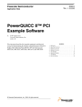
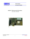
A block diagram of the whole system shown in Fig. 1.1 shows the various
modules and their interconnection. The Computer in the block diagram is an optional
connection for testing and debugging the module. This report will discuss the details of
the GPS in chapter two. We will discuss the GPS specifications, the type of data it
outputs on its ports and how this data gets parsed and stored in the microcontroller.
2
Figure 1.1 GPS Based Mobile Embedded System Block Diagram
In chapters 3 and 4, we will discuss the GSM mobile phone, the choice of phone,
how it is controlled, what AT commands are and which AT commands are used for what
purpose. Chapter five, discusses the 8-bit microcontroller and the Butterfly AVR board.
The microcontroller’s LCD controller, the USART ports, the EEPROM that is used to
store the co-ordinates, the joystick, the interrupts and few other features used in the
project are also discussed.
3
Chapter 2
GPS
2.1 GPS Overview
The Global Positioning System is a United States Department of Defense
technology used for navigation. The navigation is based on the information from a
network of satellites that transmit data to a GPS receiver. The standards and protocols
were developed by the United States DOD and are maintained by them. Currently, this
technology is available to the public free of cost as long as they have a receiver device.
There are two signals generated at 1575.42MHz (L1) and 1227.6MHz (L2) by the
satellites orbiting the Earth. Civilian satellites can receive only the L1 signals, which do
not contain much information about the signal strength or delay. Military class receivers
can receive both the L1 and L2 signals and have better accuracy and real time positioning
[1]. Generally, at least three satellites are required for 2D positioning with latitude and
longitude data. Four or more satellite visibility can help determine 3D positioning by
using the 3 coordinates altitude, latitude and longitude [1]. The most popular use of GPS
is in navigation. Commercial GPSs have maps of various locations that are used to guide
the user to get from one place to another efficiently. GPS can also be used for Geographic
mapping, survey and oceanic survey. Hikers and marathoners use GPS receivers to keep
from getting lost or to stay close to safe running and hiking paths. Before being available
to the civilians, GPS was used in the military for navigation in unknown areas. GPS still
has applications in military operations for guided missiles and bombs to strike an
adversary remotely. GPS uses atomic clocks that are very accurate in comparison to
4
clocks running on crystal oscillators. This accurate clock can be used to correct quartz
crystal clocks and also for transmission and reception of TV and Radio signals.
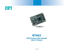
2.2 GPS Evaluation Board
The GPS receiver used in this project is the ET-312 from Globalsat Technology
Corporation. We use the SparkFun Evaluation board that has the ET-312 GPS receiver
module mounted on it along with on-board 5 Volt regulation, power over USB, Power
over 5.5x2.1mm barrel jack (center positive), status LED, 12mm coin cell backup battery
holder, Serial over USB, Serial over dual RS232 connection with all serial ports broken
out. Out of these we are going to use only the voltage regulator to get 3.3 V power supply
for the MAX232, the TX and GND pins. We can directly use the on-board MAX232
output to be connected to the USART port of the Butterfly AVR for serial
communication. The SparkFun evaluation board uses the GPIO1 pin of the ET-312 GPS
receiver to turn a status LED ON and OFF indicating that it is receiving data from the
satellites. The GPIO1 pin is the ‘one pulse per second’ (1PPS) signal that is also available
in the port breakout.
The 3.3V output from the regulator is used to power the MAX3232 IC for level
conversion. This can also be used to provide power supply for the Butterfly AVR kit. The
SparkFun evaluation board can be powered either using a USB connected to a computer
or a barrel plug connected to a source. For mobility, the barrel jack on the evaluation
board can be used with a 5V battery power supply. The coin cell back-up battery holder
5
can use a 12mm battery to power the SRAM and RTC when the power supply is
removed.
Figure 2.1 GPS Evaluation Board [2]
Without this battery, the GPS will perform a cold start whenever the evaluation board is
turned ON [2] [3]. Faster start-up can be achieved using a battery that facilitates a warm
or a hot start.
RTC stands for Real Time Clock. Real Time Clocks are important for computers
and GPS systems where the perpetual running of a clock is necessary to keep track of
time and date. Personal Computers and laptops have RTCs by default powered by a
separate coin cell battery so that it does not turn off when the computer is turned off.
Removing the battery resets the clock back to a default value and the clock runs only
6
when the system is powered on. RTC are important for monitoring systems and recording
systems that need to record the time and date of an event’s occurrence. GPS systems use
RTCs to correlate position with time dependent parameters such as weather and traffic
condition and most importantly, location coordinates. The combination of clock and
SRAM in the GPS helps GPS to decide whether the last received coordinates can be used
depending on the time difference. RTCs run on crystal oscillators powered by battery and
thus are not as accurate as atomic clocks in the satellites. These RTCs are used to
maintain an approximate time for the module. The RTCs themselves can be corrected
using the atomic clocks.
2.3 GPS Output Data
The GPS receiver puts out data in the NMEA 0183 format. This standard is set by
the National Marine Electronics Association (NMEA). The NMEA 0183 protocol is for
communication between a transmitter and one or many receivers, more like broadcasting.
The data is in ASCII format usually containing position and speed data. Although
developed for marine vehicles NMEA 0183 format has found its way into general civilian
vehicles with the use of GPS. The output is in various formats of sentences [4]. The latest
version is the NMEA V4.00 that has more sentences and features added from the older
versions. Through the ET-312 GPS receiver, we receive GGA, GSA, GSV, RMC, VTG,
and GLL sentences. In this project, time and position information were extracted from a
bundle data output by GGA messages using the microcontroller. The UTC time, latitude
and longitude data are stored in the EEPROM and displayed on the LCD.
7
2.3.1 GGA – Global Positioning System Fixed Data
Table 2.1 Example NMEA GPGGA Message
$GPGGA,161229.487,3723.2475,N,12158.3416,W,1,07,1.0,9.0,M, , , ,0000*18 [5]
$GPGGA 161229.487 3723.2475N 12158.3416W 1,07, …
*18
Message
format
Checkum
UTC time
Latitude
Longitude
Other
data
This is the general format of the GGA message received. The table explains the different
values in the NMEA output message. The UTC time is in hhmmss.ss format. The latitude
and longitude data are in the ddmm.mmmm format. Which means the example value in
the table represents 37 degrees 23.2475 minutes. North and 121 degrees 58.3416 minutes
W. Longitude data can be only between 0 and 90 on either sides of the hemisphere
whereas longitude can be only between 0 and 180. The next value represents the position
fix quality. There are different types of position fixes like, GPS fix, Differential GPS fix
(DGPS), PPS Precision Positioning Service (PPS) fix and no fix which is invalid data.
The next value, ‘07’ in the example, represents the number of Satellites being tracked. A
minimum of 2 satellites is needed to acquire any position data. The next value, ‘1.0’
represents the Horizontal dilution of precision. A HDOP value less than or equal to 1
means higher quality of data with decrease in quality with increase in number. There is
also altitude above mean sea level data given in meters followed by a value that
represents height of the geoid above the WGS84. The next is the DGPS station ID
number followed by the checksum field. The values after GGA up to the character ‘W’
are the ones we use which are the UTC time, latitude and longitude respectively.
8
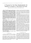
The resultant value can be directly used on google maps to check the GPS
receiver’s accuracy. One such GPS accuracy test is shown in figure.
Figure 2.2 GPS Accuracy Test 1
From the picture, we can see the searched co-ordinates shown by the green arrow. Upon
magnification it was found out that the arrow was pointing almost exactly where the GPS
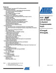
receiver was, with a precision of ±5 meters. The result of another test is shown in the
following figure with maximum magnification. We can notice that the accuracy is
reasonable for a WAAS enabled GPS receiver.
9
Figure 2.3 GPS Accuracy Test 2
2.3.2 GSA
GSA represents GNSS DOP and Active Satellites.
Table 2.2 Example GPGSA Message [5]
$GPGSA
A
3
07
Message
format
Mode1 Mode2 Satellite
used
02
Satellite
used
Other 1.8
1.0
data
PDOP HDOP
1.5
*33
VDOP
Check
sum
Mode1 can have two values M and A which stand for Manual and Automatic.
Manual means that the receiver is forced to operate in either 2D or 3D mode. Mode2 can
10
have three values to specify whether the fix is 2D, 3D or invalid. The next twelve values
give the ID of the satellite being tracked in each of the 12 channels. PDOP stands for
Position Dilution of Precision, HDOP for Horizontal Dilution of Precision, and VDOP
for Vertical Dilution of Precision. The lower these values the better data they are
receiving.
2.3.3 GSV
GNSS stands for GNSS satellites in view. This message outputs data such as
number of messages, message ID, the number of satellites in view, the satellite ID, the
elevation in degrees, azimuth in degrees and the signal to noise ratio of the received
signal in dBHz for each satellite. The number of messages value depends on the total
number of satellites in view.
2.3.4 RMC
RMC stands for Recommended Minimum Specific GNSS data. This output
message contains UTC time, data validity indicator, latitude and longitude, speed over
ground in knots, course over ground in degrees, date, magnetic variation in degrees, the
mode of operation, and the checksum field.
2.3.5 VTG
VTG output data represents course over ground and ground speed. There are data
that give the course with reference and the speed. The course reference is given according
11
to true reference and magnetic reference. The speed is given in knots as wells as
kilometers per second. The last two data are the fix mode that can be either Autonomous
or DGPS or DR and the checksum.
2.3.6 GLL
GLL represents Geographic Positioning – Latitude/Longitude. This message
outputs only the latitude and longitude along with the UTC time. This message also has
data validity information, the mode followed by the checksum field.
12
Chapter 3
GSM
3.1 GSM Overview
In the project, we use a mobile phone to transmit GPS data stored in the Butterfly
AVR board to a remote receiver module. This mobile phone works on Global System for
Mobile communication (GSM) standards. The European Telecommunications Standards
Institute (ETSI) has been the committee driving the GSM technology. The Short
Messaging Service (SMS) is used to send text messages from the local transmitter to the
remote receiver. The SMS is a feature from the evolution of the GSM standard over a few
years into General Packet Radio Service (GPRS) [6]. This was developed to increase the
data rate from the original 9600 bits per second up to 40 kilobits per second [6]. The main
components of a GSM network are discussed below briefly.
•
Mobile Equipment – The mobile equipment, sometime know as mobile station are
the cellular phones. These are the devices handled by the users that generate and
consume signals. The mobile equipment’s has components to process and
generate signals at the frequencies set by international GSM standards. There are
basic components such as a microphone, a speaker, LCD display and a keypad.
Newer generation phones have antennas that do not need to protrude out of the
phone to transmit the generated signal. There are digital signal processing (DSP)
chips and different types of memory to store phone numbers in address books and
save SMS messages. Each phone has an International Mobile Equipment Identity
(IMEI) number that is unique to it. Once a phone is bought and the activated, the
13
IMEI is recognized by the GSM network and is read every time the phone
contacts the network. This is also a feature that helps identify and report stolen
equipment and make them dysfunctional. The IMEI number cannot be changed
[9].
•
Subscriber Identity Module - The important component of the mobile equipment
is the Subscriber Identity Module (SIM). This smart chip contains information
about the subscriber such as the mobile equipment number and has small memory
to save some phone numbers and SMS messages.
•
Base Station Subsystem – The Base Station Subsystem (BSS) consists of the
signal towers that receive the wireless signals from the mobile equipment and
transfer them to a different BSS in other networks. These towers have transceivers
that communicate with the mobile equipment.
•
Cell – The term “cellular” phone comes from the fact that the BSSs form a
hexagonal cell to provide access points for the mobile equipment. A cellular
phone inside a cell accesses the nearest of the 6 BSS towers to transmit and
receive signals. There are numerous cells that form the whole GSM cellular
network. An interesting feature of these cells is that they can provide the location
of the mobile equipment based on the BSS tower being accessed by it. Although
this may not be accurate, triangulation methods can be implemented to locate the
device accurately. This feature is can be utilized as a correction method for
location or backup-locators for projects similar to ours which use GPS with cell
phones.
14
•
Network Switching Subsystem – The NSS is considered the core of the GSM
network. It has various components that facilitate communication between
networks. A component of interest to us in the NSS is the SMS gateway. The
SMS gateways are the components that route SMS messages through the network
to the recipient. In a cell phone, there usually is a dedicated number for an SMS
gateway for each service provider in an area.
This basic structure is mirrored in a number of sites for reception. The transmission and
reception of the wireless signals needs wave modulations and wave carriers of high
frequency for long distance transmission and reception with minimum loss. The BSSs
also act as repeaters that boost up the signal. There are different frequencies used for
uplink and downlink in different regions of the world.
3.2 AT Commands
Hayes AT commands were developed for the Hayes smartmodem. The ETSI has
come up with AT style commands for the GSM mobile phones. Each GSM mobile
equipment contains a modem in it, which is used to connect to the GSM network which
uses AT commands similar to the Hayes AT commands. The AT commands sent to the
phone always start with ‘AT’ followed by other symbols and characters to send specific
messages to the phone. In this project, since the main purpose of the phone is to send
SMS messages, only the following commands are used.
•
AT
•
AT*SWRESET
15
•
AT+CMGF = 1
•
AT+CMGS = Recipient address/number
AT – This command is the basic attention seeking command. The phone responds with
‘OK’ for all the commands given it. For a response other than ‘OK’, there is either an
error cause or a special response. This command is a test command to see whether the
communication is taking place or not. The devices usually echo whatever command is
being input to them. This feature can be turned off using another AT command ATE0.
AT*SWRESET – This command stands for software reset. Its function is to reset the
whole mobile equipment by turning it OFF and back ON. Upon reset, the mobile
equipment goes through its regular boot cycle.
AT+CMGF=1 – This command sets the message format for the SMS. The mobile
equipment can get input and send output SMS in two different modes namely, PDU and
Text. PDU mode contains more meta-data about the sender and routing. We use the text
mode.
AT+CMGS = “receipient #” – This is the ‘Send Message’ command. The destination
phone number or e-mail address is entered after the ‘=’ sign. The response to this
command is not an ‘OK’ but, the message reference value. When this command is
executed the phone responds with a ‘>’ to accept the text string to be sent. The
termination of the text string is marked with a ‘CTRL+Z’ value in ASCII.
There are AT commands which can be used to access the data in the phone’s SIM
card memory or the phone’s own memory. This can be used to model a system where
commands are sent to the local GSM unit from the remote GSM unit. Commands such as
16
+CMGR for message read and +CMGL for message list have been tested as shown in the
figures.
This way a communication between the microcontroller and the phone can be
established using AT commands.
3.3 The Local GSM Transmitter Equipment
In this project, a GSM phone is used as a transmitter. A suitable microcontroller is
needed to control the phone for transmission. Currently, most phones that have been used
in microcontroller based projects were using phones like Nokia that had F-Bus and MBus standard ports that were serial ports developed by IEEE.
Figure 3.1 Nokia F-bus Pin-Out
The F-bus transmits at a high baud rate of 115,200 bits per second in 8-bit serial
format [8]. The alternative M-Bus has a lower baud rate of 9600. A MAX232 level
converter is needed to convert the serial level data to TTL level for phones using either
the F-Bus or the M-Bus. Also, the type of connectors to be used are of a particular type
that will need to be probably cut off from a charger or headset cable. Another phone is
17
the Ericsson T10s. This phone is particularly of interest because its port gives a direct
TTL level output that can be interfaced to a serial port on any microcontroller. We don’t
need an extra IC MAX232 for level conversion. This reduces the size of the whole
system.
Figure 3.2 Ericsson T10s Pin-Out
This also has the same problem like the F-Bus jacks in the Nokia phones; a serial cable
will need to be made by cutting either a charger or headset cord. Another drawback is
that this phone is old and not in the market.
3.4 Motorola C168i
Motorola C168i has small size and serial communication capability makes it an
ideal candidate for use with this project. The features of phone will be discussed in
sufficient detail in the following pages. Though the phone is simple and has minimum
features it is available with an AT&T prepaid SIM card that can be activated for a
data/calling plan according to the user’s needs. Cost-wise, the phone is expensive as each
SMS message costs about 20 cents. For our design, since it is user-interactive, the
phone’s data plan to be chosen depends on how often the user sends the data to the
18
remote receiver which will be considerably less compared to an automated transmitter
that sends the data on a periodic basis. The features of Motorola C168i are discussed
below.
Figure 3.3 Motorola C168i
•
The specifications of the phone are in fact suitable for a GSM transmitter with
sufficient features to send data either as an SMS to a remote GSM module or
using the WAP2.0 http connectivity to send it to an e-mail address.
•
The phone is available from a starting price of $30 with a SIM card that can be
activated with a pre-paid calling plan or even cheaper on ebay with or without the
SIM card.
19
•
The phone’s Height x Width x Depth dimensions are 1.8 x 4.1 x 0.55 inches and it
weighs 2.75 ounces. This is a reasonable size relative to the SparkFun GPS
evaluation board and the whole module can fit inside a project box.
•
The phone works on GSM 850/1900 MHz technology where the 850/1900 MHz
represents the frequencies at which the information is transmitted between the
mobile equipment and a base station. The United States of America, Canada and
some neighboring countries use these frequencies while different frequencies are
used in Europe and Asia.
•
The next feature is what is important to us which is SMS and MMS capabilities.
MMS stands for Multimedia Messaging Service with which we can transmit
multimedia data like photos and ringtones apart from text. The phone can connect
to the internet using the WAP2.0 and GPRS connectivity.
•
The final feature that is important to us is the battery life. The Motorola webpage
for the C168i mentions that the battery life is 9.1 hours on a continuous usage
basis. The battery life also depends upon the network configuration and signal
strength [7].
•
Apart from these, the winning feature of the phone that makes it suitable for this
project is the headset jack. The headset jack acts as a serial port for the phone.
This is the communication port for the microcontroller to control the phone’s
processor to send an SMS with the GPS co-ordinates.
There are also features that are not very important to us. The phone’s battery use now
also depends on the serial communication since, serial communication uses considerable
20
amount of power. This will be a concern only if the message transmission is done at a
high frequency.
21
Chapter 4
MOTOROLA C168i
4.1 Motorola C168i Serial Port Testing
As discussed earlier, the Motorola C168i’s headset jack acts as a serial port. It can
be used with a 2.5mm 3-conductor type stereo plug for serial communication. The 2.5mm
3-conductor type stereo plugs are available in Radioshack for a little over a dollar. There
are different types of 2.5mm stereo plugs available and some are incompatible with the
Motorola C168i. Upon experimentation, we found out that the L-shaped 3-conductor type
plugs work very well. The regular plugs don not give any output. This L-shaped plug has
three terminals, Rx, Tx and GND.
In order to test the phone’s serial port we had to connect it to a computer and use
a terminal program to communicate with the phone. These terminal programs are used to
communicate with serial devices such as modems, serial ports in micro-controllers,
routers and mobile phones. There are various terminals available, the most popular being
HyperTerminal which used to come free with the Windows operating system. Microsoft
decided to stop including this package with the operating systems starting with Windows
Vista. Fortunately, there are other open source/free terminal programs created by
enthusiasts on the internet. The Br@y++ terminal is one such program that has been
popular among microcontroller programmers. This program is available at various
websites since it is free.
•
The Br@y++ Terminal shows 6 COM ports
22
•
Baud rates can be chosen between 600bps and 256kbps (inclusive) with an option
to choose a custom baud rate.
Figure 4.1 Br@y++ Terminal
•
Number of data bits can be chosen from 5 to 8.
•
Options to choose parity, stop bits and type of handshaking
•
Option to set <CR> = <LF> or <CR> = <CR>+<LF> (In GPS carriage return and
Line Feed are different paramenters.)
•
File transmit and macro transmit options
•
Scripting option for transmission and logging received data either in HEX or
string format.
23
The data to be transmitted is entered in the Transmit box in the bottom and the received
characters can be viewed in the Receive box above it. There is also a character counter in
the terminal to view the number of characters sent and received.
4.2 Serial Communication Hardware
Since, most computers these days, even desktop computers, rarely have any serial
ports, some extra hardware is needed to communicate using the available serial ports like
the Universal Serial Bus (USB). A USB to serial conversion hardware is needed in the
project for interface with laptop. With the arrival of Windows 7, the convertor is
especially, expected to be compatible with 64-bit version of Windows 7. The commFront
USB to RS232 convertor used in the project takes power from the USB port and supports
baud rates from 300bps to 128kbps with auto-sensing and self-adjusting to the baud rate
[10].
The RS232 level voltage transmitted directly onto the phone would normally fry
the phone’s electronics because of the big voltage difference between RS232 and TTL.
We use MAX3232 from Maxim ICs, which can be powered by the 3.3V power supply on
the SparkFun evaluation board port breakout. The difference between MAX232 and
MAX3232 is that the latter is faster than the former and can work on power supply
between 3V and 5V while the former needs a 5V power supply. The pin configuration for
the MAX3232 IC can be found on Maxim’s website. After the proper connections were
made, we tested the serial port of the phone by sending AT commands to access the
phone’s address book. The command to access a number in the address book is
24
AT+CPBR = ‘location number’. We were able to see the requested phone number on the
Br@y++ Terminal as shown in figure
Figure 4.2 Communicating with Motorola C168i using Br@y++ Terminal
As seen in the figure, the phone’s GSM modem responds with ‘OK’ for every successful
execution of the commands it receives. The format for the various AT commands and the
possible responses from the phone are given in the AT commands reference available on
the Motorola website. The baud rate used test the serial communication initially was
4800bps. Upon further testing, it was found that the phone’s modem is able to
automatically sense the baud rate, adjust its own and respond properly. The Motorola
C168i is able to communicate from 600bps up to 115.2kbps baud rate without problem. It
was also noted that the phone’s modem has a very short timeout period because of which
25
sometimes there is no response from the phone. Due to the short timeout period, there is
also some character loss in the phone and characters need to be repeated.
26
Chapter 5
THE MICROCONTOLLER
5.1 AVR Butterfly Board with ATmega169 Microcontroller
The AVR Butterfly board is an evaluation kit designed to demonstrate the features
of different AVR microcontrollers by ATMEL. The AVR Butterfly kit utilized in this
project houses am ATmega169 8-bit microcontroller. The Butterfly AVR board has the
following features apart from the ATmega169 microcontroller.
1. LCD display with 120 segments
2. 4-direction joystick with center push for user input.
3. 32kHz crystal for Teal Time Clock
4. RS232 level converter
5. 3V cell battery for operation
6. Supported by AVR Studio4
7. USI interface for secondary serial communication option
8. Negative
Temperature
Coefficient
(NTC)
Thermistor
for
temperature
measurement
9. Light Dependent Resistor (LDR) to measure light intensity
10. 4Mbit DataFlash flash memory
11. JTAG emulation for debugging
12. Pre-programmed demonstration application with bootloader
Features 1 through 6 are of significance to our design. The 120 segment LCD display is
used to display the GPS co-ordinates. The details on the LCD can be found on the
27
STK502 datasheet from ATMEL. The demonstration program that comes with the AVR
butterfly contains functions that allow users to display information on the LCD. The
AVR Butterfly uses a miniature joystick that acts as an input port for the user by
generating interrupts to the microcontroller.
Figure 5.1 Butterfly AVR Joystick [12]
The joystick can move in four directions and allows a center push. Each of these actions
generates a signal, which is connected to different ports of the ATmega169
microcontroller. These signals have a common ground.
The button cell battery provides a 3V power input to the Butterfly AVR which
can last a while if UART port is not used extensively. The serial communication drains
out the battery considerably fast due to which an external 3V power supply from two
1.5V D batteries is utilized for development purposes. The Butterfly AVR has small
features. It is 45mm x 65mm x 14mm in dimensions and weighs 28 grams. It aligns
perfectly with the SparkFun evaluation board and can be placed right above it with
28
screws. The on board thermistor and voltage readers have ±1°C and ±1V precision of
approximation respectively.
5.2 Menu System
The Butterfly AVR is shipped with a firmware that demonstrates all the features
and peripheral interfaces that the ATmega169 supports. This firmware displays a menu
system using which the features and modules in the application are navigated easily. The
joystick is used to navigate through the menu. Table 5.1 lists the functions for each
joystick movement in the menu. The menu system is implemented by creating a Moore
Finite State Machine (FSM) where each state is a menu item. The state transition takes
place based on the input given by the user using the joystick and the each state has an
output that is displayed using the LCD. We have adapted this FSM based menu system
for the GPS based embedded system to display a list of items in a menu that the user can
choose.
Table 5.1 Butterfly AVR Joystick Functions
DIRECTION
FUNCTION
Up
Scroll up
Down
Scroll down
Left
Exit sub-menu
Right
Enter sub-menu
Center Push
Enter
29
The AVR Butterfly includes a bootloader that enables users to program the
ATmega169 using its self-programming feature. Users need not use any external
programmer boards to upload their application on the microcontroller because of this
feature. The bootloader combined with the RS232 level converters lets us program the
microcontroller with the USB to RS232 convertor we already have. The data is
transmitted using the UART interface. The AVR Butterfly enters the bootloader the
moment it is powered on. In this mode, there is nothing displayed on the LCD. To enter
the application mode, the joystick has to be moved in the up direction. Once the
application mode is entered, the LCD displays a string. To enter the bootloader mode
again we can either remove and reinstall the battery or short Pins 5 and 6 of the ISP
connector. To program the ATmega169 in the self-programming mode, we need to press
and hold the joystick in the center-push position and hit ‘AVR Prog…’ in the Tools menu
of the AVR Studio 4 software.
5.3 AVR Studio
The AVR Studio 4 is a free Integrated Development Environment (IDE) provided
by ATMEL for AVR microcontroller programming and debugging. It is compatible with
a wide variety of AVR devices and programmer boards. AVR Studio provides a front-end
tool for source code editing in C/C++, project management, assembling, simulation, onchip debugging and emulation. This tool can compile the code and generate the ‘.hex’ file
that needs to be uploaded into the microcontroller. The AVR Studio simulator can show
us the output of our code using the simulator without an actual hardware. The parameters
30
can be set on the simulator for the resources being used in the design and the output can
be viewed on the simulator. The AVR Studio allows interaction with third party software
to add plug-ins and add-ons. One such plug-in is the avr-gcc compiler developed by the
GNU project. AVR Studio recommends the WinAVR distribution of the ave-gcc
compiler for programming the microcontroller using C language. The WinAVR is a set of
configuration and source files that specify how a source code is compiled, built, linked to
other source codes in a project and an executable is generated.
5.4 ATmega169 Microcontroller
The ATmega169 is the brain of the GPS based embedded system. As mentioned
earlier, it is an 8-bit RISC microcontroller modeled on a Harvard Architecture. It is a
sixty-four pin CMOS microcontroller in Quad Flat No leads/Micro Lead Frame
(QFN/MLF) package. It has 16k bytes in-system programmable flash memory with two
sections, one for application program and another for boot program. These two sections
are separated by lock bits so that software does not write into the boot section of the
program memory. The Program memory is divided into sections of 16-bit wide spaces
since most instructions are either 16 or 32 bits wide. The program counter (PC) is 13 bits
wide and can address 213 = 8k program memory locations. The data memory is made of
SRAM where the lower 1280 data memory locations are used to address the 32 register
files, I/O memory, Extended I/O memory and data memory. The data memory is only
1024 bytes. The instructions are pipelined such that when the one instruction is being
executed, the next instruction is fetched from the instruction register. This makes one
31
instruction execution per cycle possible. The ALU can operate on two registers or a
register and an immediate value, which can be directly accessed from the 32 general
purpose registers. The CPU can fetch operands from the 32 general-purpose registers,
execute the operation and write the result back into the registers in one clock cycle. The
16k byte flash memory in the ATmega169 is non-volatile because they are made of Flash
ROMs, which can be erased and reprogrammed using special software and hardware
techniques. Since, we are using C language to write applications, we need memories that
can be written into to maintain the stacks for routines and interrupts. In fact, the stack can
be as big as the internal SRAM data memory depending on SRAM’s usage in the
application since, the stack is stored in the SRAM. Any definition of constants in the
program, the compiler would put the data in the SRAM data memory. This will use the
limited RAM available in the AVR. This is because AVR is based on Harvard
architecture and uses Flash for program storage and SRAM for data storage while C
language is designed for Von Neumann architectures where code and data reside in the
same address space. For this reason, WinAVR uses special attributes and methods to
store data in the program space and access them for AVR applications. The constants in
the menu.h file are stored in the Flash using the PROGMEM macro that stores and
retrieves variables from the program space.
5.4.1 EEPROM
The ATmega169 has a 512 byte EEPROM in addition to the flash memory. In this
project, the EEPROM is used to store the GPS data. Generally, a byte can be read or
32
written in the EEPROM. The EEPROM is arranged as pages with each page being 4
bytes in size giving a total 128 pages. A page buffer is used to store all the data before it
is programmed into the EEPROM. This way, a whole page of data of 4 bytes is written
simultaneously into the EEPROM. The Page buffer is latched to the data and when the
buffer is full, it is written into the EEPROM. This method is used for parallel
programming of the EEPROM. Special procedures need to be followed to write data into
the EEPROM. The EEPROM address registers have EEARL and EEARH bits of which 9
through 15 are reserved and bits from 0 through 8 of this register are used to address 512
bytes of memory.
The address register EEADR is an 8-bit register which stores the data to be
written into the EEPROM address in EEAR during a write operation. During the read
operation, the EEADR stores the data read from the address in EEAR. There is a write
time of two clock cycles and read time of four clock cycles for the EEPROM before any
other instruction is executed following the read or write. The EEPROM control register
EECR has four bits to set or erase Master Write Enable (EEMWE), Interrupt Enable
(EERIE), read enable (EERE) and write enable (EEWE).
Bit 3 is the EERIE bit that generates an interrupt when the status register I-bit s
also set. This continuously generates the EEPROM ready interrupt.
Bit 2 is the EEMWE bit which controls whether the EEWE can write the
EEPROM or not. The EEWE bit has to be set within four clock cycles after the EEMWE
is set for a write to take place. The EEMWE is reset by hardware 4 click cycles after it is
set.
33
Bit 1 is the EEWE bit. EEMWE bit has to be set to one before the EEWE is set to
one. When the data and address are available, the write enable bit is set to write the data
into the particular address of the EEPROM. It is suggested in the datasheet that a
procedure be followed to write this bit.
1. Wait for EEMWE to become zero
2. Write the address where the data needs to be stored in the EEAR register
3. Write the data to be stored in the EEDR register
4. Write a one to the EEMWE and a zero to EEWE simultaneously
5. Write a EEWE bit to one within 4 clock cycles of setting the EEWME
The global interrupts are supposed to be disabled during this process so that the address
registers and data registers are not altered when the EEWME is set after step four.
Bit 0 is the Read enable bit EERE. Similar to the write enable bit, when the
address is available and the read enable bit is set the data is read. There is a four clock
cycle time before the following instruction when a read takes place. The EEWE has to be
polled to see whether it set since a read is not possible if it is already set. A sample
procedure to write to the EEPROM is shown in the ATmega169 datasheet.
Writing:
void EEPROM_write(unsigned int uiAddress,
unsigned char ucData)
{
/* Wait for completion of previous write
*/
while(EECR & (1<<EEWE))
;
/* Set up address and Data Registers */
EEAR = uiAddress;
34
EEDR = ucData;
/* Write logical one to EEMWE */
EECR |= (1<<EEMWE);
}
/* Start eeprom write by setting EEWE */
EECR |= (1<<EEWE);
A similar procedure can be followed for reading the data from the EEPROM.
5.4.2 ATmega169 Clocks
There are different clocks distributed throughout the microcontroller. The CPU
clock is used to clock the general purpose registers, status registers and data memory
holding the stack pointer. Halting the CPU clock will stop the CPU from working. The
I/O clock is used by Timer/counters, USART and SPI. This is also used by external
interrupt modules. The flash clock is used to control the flash memory interface. This
clock is usually synchronous with the CPU clock. The asynchronous timer clock allows
the asynchronous timer/counter and LCD controller to be controlled by the 32kHz clock
crystal. This clock can be used as a real-time counter during sleep modes. The ADC
clock has a dedicated clock domain, which allows the CPU and other clocks to be halted
thereby reducing noise and increasing the accuracy of ADC conversion results.
The ATmega169 clock select bits CKSEL are set to internal calibrated RC
oscillator and clock division 8 by default. The crystal oscillator can be configured as a
clock source in three different modes for different frequencies using the CKSEL 3-1 bits.
The low frequency crystal oscillator uses the 32kHz crystal as a clock source when the
CKSEL bits are set to external low-frequency crystal. The calibrated internal RC
35
oscillator provides a fixed 8MHz clock. The clock division is pre-programmed to 8 and
the internal oscillator can be set as the system clock using the CKSEL bits. A preprogrammed calibration byte is stored in the oscillator calibration register. OSCCAL.
This calibration value sets the frequency output by the internal RC oscillator with a zero
giving the lowest frequency and higher values giving higher frequencies. This calibrated
oscillator is used for the EEPROM and flash memory accesses. The external clock source
can be used to drive the XTAL1 pin. The CKSEL bits can be set to select from these
modes according to the table shown.
The system clock can be used to drive circuits outside the microcontroller by
setting the CKOUT fuse. The output is obtained on CLKO and the I/O is overridden
when the fuse is set. Any clock source can be used to be output in the clock output buffer.
Table 5.2 ATmega169 Clock Sources
Clock Option
CKSEL 3-0
External Crystal/Ceramic resonator
1111 – 1000
External Low Frequency Crystal (32kHz)
0111 – 0110
Calibrated Internal RC Oscillator
0010
External Clock
0000
Reserved
0011, 0001, 0101, 0100
The Timer/Counter oscillator shares the TOSC1 and TOSC2 pins with the
XTAL1 and XTAL2 pins. This means that TSOC1 and TSOC2 can be used only if the
calibrated internal RC oscillator is used as the system clock. This oscillator is optimized
36
for use with the 32kHz crystal. The ATmega169 clocks can be divided using the prescaler bits by setting the CLKPR register bits. This is used to reduce clock frequency and
thereby reducing the system’s power consumption. The pre-scaler value affects all clocks
from system clock to peripheral clocks. To set the CLKPR bits, all the interrupts must be
disabled so that the write is not interrupted.
•
The pre-scaler enable bit CLKPCE must be set first
•
The pre-scaler value must be set using the CLKPS 3 – 1 bits while writing a zero
into the pre-scaler enable bit.
This makes sure that no setting in the pre-scaler is unintentional and no glitches are
encountered between frequency changes.
5.4.3 Sleep Modes
Figure 5.2 shows the clock systems and their distribution in the ATmega169. This
helps in determining the sleep modes and their settings so that appropriate clocks can be
stopped. The sleep modes help saving power by turning off certain modules in the
ATmega169. The sleep mode control register SMCR bits need to be set to choose from
the 5 sleep modes available namely, Idle, ADC Noise Reduction, Power-down, Powersave and standby. The Sleep Enable bit SE has to be set before any of these modes can be
entered. To avoid unintended changes, the SE bit is to be set just before entering the sleep
mode and reset immediately after waking up. The SLEEP instruction is executed to enter
the sleep mode.
37
Figure 5.2 ATmega169 Clock Distribution [11]
When waking up from a sleep mode, the register files and SRAM remain
unaltered so that the microcontroller can resume operation from the point before entering
the sleep mode.
In the Idle mode, the CPU clock and Flash clock are halted allowing all other
clocks to run for the LCD controller, USART, SPI and others to function. In the ADC
Noise Reduction mode, the I/O clock, CPU clock and flash clock are halted to reduce
noise and improve the resolution of measurement for the ADC. There are some interrupts
that can wake-up the MCU from this mode. In the Power-down mode, the external
oscillator is halted. When waking up from this mode, there is a stabilization time
involved apart from the wake-up time. Only an External reset, a watchdog timer reset,
38
USI start condition interrupt or a pin change interrupt can wake the microcontroller up
from this mode. The Power-save mode is similar to the Power-down mode except that if
either the LCD controller or the Timer/Counter2 or both are enabled, they continue to run
in the sleep mode. A synchronous or asynchronous clock may be used with the LCD or
Timer/Counter2, which is available only to these modules. This mode is to be used only
if these two modules need to be running otherwise, the Power-down mode is
recommended. The standby mode keeps the oscillator running and the device wakes up
six clocks cycles after entering this mode.
The Power Reduction Register PRR controls the clocks used by the peripheral
modules. We can shut down different clocks when necessary by setting the PRR bits to
reduce power consumption. The peripheral whose clock is turned off is frozen and the
I/O registers cannot be accessed. Since, all the resources used by the peripheral are
occupied, it is recommended that the device be disabled before stopping its clock. The
PRR register is used to stop the clocks of USART, SPI, LCD controller and
Timer/Counter1.
5.4.4 Interrupts
Interrupts are important concepts in microcontrollers and microprocessors. The
name is self-explanatory suggesting that it interrupts a flow of process to get attention so
that whatever process generated the interrupt can be handled. When an interrupt is
generated, the microcontroller halts whatever it is doing, stores the states of whatever
processes are going on, services the interrupt and then restores the system from the saved
39
point. Another option to deal with such processes is to poll. In polling, the processor
periodically checks if some process other than the running process needs to be serviced.
It is a time consuming job to, periodically look for processes that need servicing. In the
ATmega169, the reset and interrupt vectors are stored from the lowest addresses in the
program memory. The priority of the interrupt vectors decreases from the lowest address
to the highest address. When an interrupt occurs, the global interrupt enable bit is cleared
and all other interrupts are disabled until the current interrupt is serviced. We can set the
Global interrupt enable bit using software to facilitate nested interrupts. After the
interrupt is serviced, the global interrupt enable bit is set and all other interrupts are
enabled. Interrupts are generated by events when they set the interrupt flag. If interrupts
occur when the global interrupt enable bit is cleared, the corresponding flags are set and
stored until the global interrupt enable is set again. The interrupts are then serviced in the
order of priority. There is a second type of interrupt, which is triggered if the interrupt
condition is present. If the interrupt condition vanishes before the interrupt is enabled, it
is not triggered. In an AVR, after an interrupt has been serviced, the microcontroller
returns to the main program and executes one instruction before it services any pending
interrupts.
Following the reset interrupt vectors, external interrupts have next priority
followed by Timer/Counter1 and Timer/Counter2 compare match and overflow events
and other interrupt sources. The external interrupts are triggered by the INT0 pin or any
of the PCINT 15 - 0 pins. Any change in the pins PCINT 15 – 8 will trigger the PCI1 and
any change in the pins PCINT 7 – 0 will trigger the PCI0 interrupt. The PCIMSK1 and
40
PCIMSK0 registers are used to choose the pins, which can cause the PCI1/0 to trigger on
a value toggle on their pins. The External Interrupt Mask register EIMSK and the
External Interrupt Flag Register EIFR are used to set whether PCI1 and PCI0 pins can
trigger an interrupt upon a toggle in their pin values. In this project, the joystick on the
Butterfly AVR board is connected to the pins of Ports B and E and acts as a source of Pin
Change Interrupt.
5.4.5 I/O Ports
The ATmega169 has 53 programmable general purpose I/O grouped as 6 8-bit
ports and a 5-bit port. Each port has 3 I/O memory locations allocated for
1. Data Register, PORTx
2. Data Direction Register DDRx and
3. Port Input Pins PINx
where x stands for the numbering letter of the ports. The Data Direction Register is used
to set the direction for the pins of the port. Writing a one in this register sets the pin as an
output and a zero sets it as an input. The pins in PORTx register are set to a value of one
will switch the pull-up resistor on when configured as input and will switch the pull-up
resistor off when configured as output. The PINx register is a read-only register that can
only read the value on the pin. However, writing a one to PINx toggles the PORTx
register value of that pin. The PINx register can be used to read a value of a pin
regardless of whether it has been set as input or output. Most I/O ports have alternate
functions apart from being general purpose I/O pins.
41
5.4.6 UART Port
We use the UART port for asynchronous transmission of data to the phone and
reception of data from the GPS receiver. The baud rate calculation for a particular clock
frequency is obtained from the table in the ATmega169 datasheet. These values differ
based on double speed mode. The double speed mode is available only for asynchronous
transmission and reception of data. The baud value is set in the UBRR register, which is
calculated to be 51 for 4800 bits per second. We use 4800 bits per second for both the
phone and the GPS receiver because the phone can sense the baud rate automatically and
adjust to it whereas; the GPS receiver is pre-configured for 4800 bits per second, which is
the standard rate. The clock pre-scaler values are set in the CKPR register and double
speed mode is set in the UCSRA register. The transmission and reception can be enabled
in the UCSRB registers with asynchronous mode set in the UCSRC register.
5.4.7 LCD Controller
As we saw in section 5.3.4 about the I/O ports, the LCD is connected to ports A,
C, D and G. because of this we only have a limited number of general purpose I/O on the
Butterfly AVR. We will not discuss the LCD controller since it is not the major part of
the project.
42
Chapter 6
WINAVR
6.1 WinAVR Tools
WinAVR is an open source software development suite developed by Atmel AVR
8-bit RISC microcontroller enthusiasts for AVR programming. The suite includes the
GNU compiler collection, avr-libc C library, avrdude programmer, avr-gdb debugger,
Programmers’ Notepad for editing and other tools. The avr-libc library has various
macros and functions that enable the use of program memory for storing constants and
saving the small amount of available RAM. The WinAVR suite provides porting
functions to port software codes from IAR to GCC. IAR is a commercial compiler used
by Atmel to write software applications for various AVR microcontrollers. GCC is Free
Software Foundation’s open source compiler collection used by WinAVR to create
software applications for AVR microcontrollers.
To create the executable file that can be uploaded into the microcontroller, certain
steps need to be followed. In the Programmer’s Notepad editor, under the ‘Tools’ menu
there are three options, ‘Make All’, ‘Make Clean’ and ‘Program’. The ‘Make Clean’
option cleans the memory sections that store compiled data. The ‘Make All’ option
compiles the code and creates executable data. The ‘Program’ option is not used since
AVR Studio 4 is used to program the Butterfly AVR. Apart from these options, an option
to create the ‘.hex’ file is needed. This ‘.hex’ file is imported into the microcontroller.
AVR Studio 4 is used to import the hex file into ATmega169.
43
Chapter 7
DESIGN AND OPERATION
7.1 The Menu System
Figure 7.1 The GPS Based Mobile Embedded System Menu
In this design, there are three menu items. The introductory message, the AT
command list and the GPS coordinate display. The first menu item simply displays a
message on the LCD as soon as the system is powered on. This is the reset state of the
system. However, during sleep modes, the wakeup states might be different for different
settings. The text is stored in the program memory. The second menu item is ‘AT
commands’ which has a sub-menu with a list of AT commands that can be sent from the
Butterfly AVR. When this menu is entered, the interrupt calls a function that displays a
44
message on the LCD indicating what the menu item does, in this case show the various
AT commands available. There are basically, three AT commands that can be sent and
the fourth sub-menu option is displaying the data stored in the EEPROM that has to be
attached as the text to be sent using the phone. Each sub-menu item when entered, calls a
function that will display an AT command which can be sent to the Motorola C168i
phone using the UART pins. The third menu item displays the data stored in the
EEPROM. This data is the parsed data from the raw NMEA format output. When this
menu item is entered, the interrupt calls a function that pulls the data from the EEPROM
and displays it on the LCD. This menu item has a sub-menu that calls a function to
receive new data from the GPS receiver, parse it and store it at an address in the
EEPROM. The menu system is based on a finite state machine that changes states
according to the input generated by the joystick. It is a Moore machine where the output
of the state is a function of the current state. The center push input of the joystick is used
in all the four sub-menu items of the AT_commands_state to send the respective
command to the phone through the UART port. When the state transition from
show_EEPROM_data to update_cordinates_state occurs the system automatically returns
to the show_EEPROM_data state after receiving and storing new data from the GPS
receiver without an input from the joystick. The *SWRESET command is an option
command. The phone does not need to be reset every time a data transmission has to take
place to the remote phone.
45
Figure 7.2 The GPS Based Mobile Embedded System FSM
7.2 Storing the Received Data
The EEPROM has been discussed in sufficient detail in section 5.4.1. This section
discusses how to store the data in the EEPROM and how to retrieve it. $GPGGA data is
used to extract time and position parameters. The GGA data has eighty characters in total.
We do not need the whole eighty characters but only characters zero through forty one,
character in position zero being the ‘$’ symbol. A buffer is used to temporarily hold the
received data before writing it into the EEPROM. The algorithm recognizes the start of
NMEA commands by the dollar sign in the input. From the moment the dollar sign is
46
received, the counter increments either until the buffer is filled out or until the ‘*’
character is received since it denotes the end of any NMEA data.
The parsed data is forty-six characters long. A maximum of eleven data elements
can be stored in the 512-byte EEPROM with each data element being forty-six bytes long
for forty-six characters. The data is stored starting from location zero and the address is
incremented for each character. The WinAVR suite’s avr-libc library provides an
eeprom_write_byte (uint8_t *__p, uint8_t __value) function which can write a byte
__value at EEPROM address __p. The implementation is based on polling. The
application that wants to write the EEPROM first has to make sure that the EEPROM is
available for access. The avr-libc provides functions such as eeprom_is_ready() to poll
the EEPROM. Apart from reading and writing bytes, the avr-libc also provides functions
to read or write words and double words. There is also a function to write a block of n
bytes.
7.3 DataFlash
DataFlash is an Atmel brand flash memory. The Butterfly AVR is shipped with an
external four-megabit flash memory AT45DB041B for data storage purposes. The
DataFlash is a serial interface memory, which can be programmed only in serial fashion.
Although this may be slow, it reduces the pin count and the overall size of the memory.
Furthermore, the DataFlash can be programmed at a maximum clock frequency of
20MHz. The DataFlash has a total of eight pins namely, CS, VCC, SCK, SI, SO, WP,
RESET, RDY/BUSY and GND with the chip select signal CS, BUSY and write protect
47
signal WP being assert low signals similar to an SPI interface. The DataFlash is
connected to port B pins of the ATmega169 microcontroller and also to the SPI ports.
This facilitates that the DataFlash use by the ATmega169 as well as external access
through the SPI.
The DataFlash consists of a Flash Memory Array, two buffers and an I/O
interface. The flash memory array is arranged as 2048 pages each page being 264 bytes
wide. The two buffers are also each 264 bytes wide. These buffers are made of SRAM
and act as cache for the main memory. Being static RAMs, they do not need refreshing
but, the data in them may be lost if the power supply is lower than the required amount to
retain the data. The presence of two data buffers facilitates read-while-write functionality.
The chip select signal is asserted low before the data or address is provided to the I/O.
For either a read or a write, the DataFlash is provided with an opcode followed by
twenty-four bits, the first 4 of which are reserved, the next eleven are used to select a
page out of the 2048 pages and the next 9 bits are used to select a byte in the page. There
are 32 don’t-care bits following the 24 bits. The external flash memory can be used to
store more GPS co-ordinates if necessary.
48
Chapter 8
CONCLUSION
8.1 Results
In this project, the GPS coordinates were received, parsed and successfully stored
in the EEPROM. The presence of the data in the EEPROM is verified by the fact that the
data is accessed and shown on the LCD even after a system reset and that the program
memory or the data memory usage does not increase . Through this project, I learned
about the Atmel ATmega169 microcontroller, the Butterfly AVR board, its peripherals
and about how to program an AVR microcontroller. I learned about the C compiler and
libraries available with the WinAVR toolset for AVR programming. Figure 8.1 shows the
compiler results.
Figure 8.1 ATmega169 Memory Usage
49
The Atmega169 has the self-programming feature and starts the bootloader using
which we program it. The UART port is used for this purpose. This feature was first
tested and a message was sent from the Br@y++ Terminal to test the UART functionality
and LCD display as shown in Figure 8.2.
Figure 8.2 UART Test
Figure 8.2 shows testing the Butterfly AVR board’s UART port using Br@y++
Terminal. The string “SACSTATE” is sent from the laptop. The string is received and
displayed on the LCD.
After the tests, we programmed the microcontroller with the code to receive, store
and display the GPS message. The joystick was used to select the options to receive the
data. The data was received at 4800 bits per second.
50
Figure 8.3 GPS Data Output
Figure 8.3 shows the received data displayed on the LCD of the Butterfly AVR
board. The picture shows the UTC time received from the GPS receiver. We extract the
time, latitude and longitude from the GGA message and display them in the same order in
easily understandable form. UTC stands for Coordinated Universal Time. This is used by
the United states Navy and is the world time from which time in the rest of the world is
calculated. The Pacific Standard Time (PST) is 8 hours behind the UTC. In the figure, the
numbers 03, 38 and 5 represent the hour, minute and second values respectively. This
data is followed by the latitude and longitude in a scrolling fashion.
This data resides in the EEPROM. The EEPROM has 100,000 erase/write cycles
endurance. Since, this data is to be sent to a remote GSM cell phone, the joystick is used
to navigate the menu items to send the appropriate AT commands to the phone to
complete the wireless data transmission. Figure 8.4 shows a few of the menu items. The
microcontroller communicates at 4800 a baud rate. The data is sent to a number stored in
the microcontroller’s memory.
51
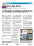
Figure 8.4 Some Menu Items in the Module
Figure 8.5 shows the message received by the remote phone. The UTC time, the
latitude and longitude data are seen on each line. The latitude and longitude are in
ddmm.mmmm format as mentioned earlier.
Figure 8.5 Remote Phone Message with GPS Data.
52
8.2 Future Work
In the future, this project can be improved for performance by using the GSM
network to determine the location of the local phone when the GPS receiver is unable to
establish strong connections with satellites due to heavy foliage or surrounding buildings.
The GSM network can provide the cell information based on the base stations the phone
is contacting periodically. Using this information, we can also validate the GPS. Another
improvement that would be very helpful would be to implement a second UART port so
that the local phone and the GPS receiver both can have individual serial ports to
communicate with the microcontroller. Since, the phone and the GPS receiver are sharing
the one UART port currently, the phone’s memory cannot be read. If the software
implementation of UART is done, commands can be received from remote phones to
configure the mobile system according to user needs.
53
REFERENCES
[1] Air University, (Air Command and Staff College Space Research Seminars), AU-18
Space Primer, Air University Press, Maxwell AFB, Alabama, September 2009.
[2] SparkFun Electronics, GPS Evaluation Board, [Online]. Available:
http://www.sparkfun.com/commerce/product_info.php?products_id=8334, [Accessed:
April 1, 2010].
[3] Product User Manual GPS Engine Board ET-312, Globalsat Technology Corp.,
Chung Ho City, Taiwan, 2000.
[4] Coleman, R., “A Self-Healing Plug-in Parser for NMEA Streams”, Fifth International
Conference on ITGN 2008, April 2008, pp. 1024.
[5] NMEA Reference Manual, SiRF Technology, Inc., San Jose, CA, 2005, pp. 2 – 7.
[6] P. Decker, “A Packet Radio Protocol for Group Communication Suitable for the GSM
Mobile Radio Network”, 5th IEEE International Symposium on Personal, Indoor and
Mobile Radio Communications, 1994, pp. 934 – 935.
[7] Motorola C168i MOTOMANUAL, Motorola, Inc., 2007.
[8] Khaled, S.M., Karim, M.R., “A Proposed Low-cost Security System Based on
Embedded Internet Control”, SICE-ICASE International Joint Conference, 2006, pp 92 –
94.
[9] Rahnema, M., “Overview of the GSM system and protocol architecture”, IEEE
Communications Magazine, August 2002, pp. 92-93.
[10] USB to RS-232 Converter, Commfront Communications, Potomac, MD, 2009.
[11] 8-bit AVR Microcontroller with 16K Bytes In-System Programmable Flash, Atmel
Corporation, San Jose, CA, 2006.
[12] AVR Butterfly Evaluation Kit User Guide, Atmel Corporation, San Jose, CA, 2005.