1
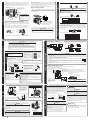
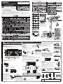
THE CHOICE OF MOUNTING SITE (Please note the following matters and obtain permission from customer before installation).
WARNING
The unit should be mounted at stable, non-vibratory location which can provide
full support to the unit.
Indoor Unit
INDOOR UNIT
HITACHI SPLIT-UNIT AIR CONDITIONER
INSTALLATION MANUAL
Outdoor Unit
RAS-X18HAK + RAC-X18HAK
No nearby heat source and no obstruction near the air outlet is allowed.
OUTDOOR UNIT
Carefully read through the procedures of proper
installation before starting installation work.
The sales agent should inform customers regarding
the correct operation of installation.
The air blown out of the unit should not point directly to animals or plants.
Do not install at a location where there is flammable gas, steam, oil and smoke.
SAFETY PRECAUTION
s Read the safety precautions carefully before operating the unit.
s The contents of this section are vital to ensure safety. Please pay special attention to the following sign.
WARNING ...... Incorrect methods of installation may cause death or serious injury.
This sign indicates prohibition.
CAUTION ....... Improper installation may result in serious consequence.
Be sure that the unit operates in proper condition after installation. Explain to customer the proper operation and maintenance of the unit
as described in the user’s guide. Ask customers to keep this installation manual together with the instruction manual.
The installation height should be at least 2.3m or more from the floor.
Names of Indoor Components
No
Component’s Name
1
1
Figure showing the Installation
of Indoor and Outdoor Unit.
The Length of Indoor Unit
Power Cord
Qty
Mounting Plate
about
0.9m
about 1.6m
Do not alter the power cord.
Screw for Mounting Plate
2
10
(4.1x32)
Cut away shaded
portion, and finish
the edge of the
opening so that
there is no burr.
AAA Size Battery
2
3
Remote Controller
Direction of Piping
1
4
Horizontally
backward
Bush
Drain pipe
1
6
Piping configuration may be
in six different directions:
direct rear piping, left or right
downward piping and left
or right sideways piping.
20m
2
5
Heat insulating materials
7
1
Items 5 & 6 are included in the
package of the outdoor unit.
Dimension of Mounting Stand
of the outdoor unit
(unit : mm)
200mm
340
50mm
299
320
Above 50 mm when installed
on the ceiling of balcony
12
500
792
200mm
Heating efficiency will be
enhanced if the space below the
outdoor unit is closed so that
no air passes through.
For outdoor unit installation, allow at least
(Procure the material locally.)
2 sides of space around the unit to ensure
ventilation flue.
1 Installation of Mounting Plate, Wall Penetration and Installation of Protection Pipe
2
INSTALLATION OF COOLANT PIPES AFTER CONNECTION
Installation of the Indoor Unit
The coolant pipes should be adjusted to fit into the
hole on the wall and then ready for further connection.
The terminals of 2 connected pipes must be covered
with insulator used for terminal connection.
Connect the power cord.
After adjustment, fit the power cord and pipes into
the space available under the indoor unit.
VERTICALLY DOWNWARD PIPING
CAUITON
The drain hose can be installed from the lefe or right of the indoor unit.When installing
the indoor unit,the mounting board must be fixed horizontally or slightly tilted down
towards the side of drain hose.If it is tilted above the side of the drain hose,condensed
water may overflow.
Preparation
Connect power cord.
Pull out the pipe, power cord and drain hose.
Power line, pipe and
drain hose must be
tied together with
plastic tape.
Installation
Direct Mounting On The Wall
Please use hidden beams in the wall to hold the mounting plate.
The upper part of the indoor unit is hanged
on the mounting plate.
The projection at the lower part of the indoor
unit is hooked onto the mounting plate.
Coolant pipe
Wall hole
Protection
Pipe Drain Hose
Lift the body
of the unit
upwards and
then force
it downwards.
Mounting
Plate
Projection
Power Cord
Please pull the lower part
of the indoor unit
outwards to check if the
unit is hooked onto the
mounting plate. Improper
installation may cause
vibration and noise.
Hook
Drain hose
INDOOR UNIT
Procedures to fix the mounting plate.
1. Drill holes on wall.
(As shown below)
Preparation
Pipe
Plug
Drain cap
Temporary stand
Hang the indoor unit onto the mounting plate. Use the temporary
stand at the back of the indoor unit to push its lower part 15cm
forwards.
Place the drain hose through the hole on the wall.
Insulate the connecting portion of coolant pipe with insulator.
Connect the power cord.
After adjustment, the power cord and coolant pipes are placed
into the space available under the indoor unit.
The projection of indoor unit must hook to the mounting
plate.
Drain Hose
Drain hose
Coolant pipes
Drain cap
Drain hose
Power cord
Please insert
until here
Please insert
until here
3
4.1 x 32 screw
CAUITON
Wall Penetration and Installation of Protection Pipe
< E4340B : A >
2~5mm
WALL
Seal with
putty
Sleeve of
protection
pipe
CAUITON
Be sure that the wire is not
in contact with any metal
in the wall. Please use the
protection pipe as wire
passing through the hollow
part of the wall so as to
prevent the possibility of
damaged by mouse.
Hook
about 15cm
Drain
hose
Power cord
Connected
terminals
of coolant
pipes
Installation of Drain Hose
Condensed water may leak out if not inserted properly.
CAUITON
HORIZONTAL & DOWNWARD PIPING – MAKING OPENINGS
Outdoor
Indoor
Projection
Protection
pipe
Pull this to the front
during the connection
of coolant pipes to
ease task.
Remove the cap for drain hose installation
Wall
below
5mm
Please bend at a small
radius to form an arc
Heat insulation
pipe
above 50mm
Protection
pipe
Please fix in the plastic
core after flaring to avoid
plastic chips entering the
pipes.
Match the end of the refrigerating pipes with the
locations marked with “ V ” symbol.
Ceiling
1 Hanger
Drill a ø 65mm hole on wall
which is slightly tilted
towards the outdoor side.
Drill the wall at a small angle.
Cut the protection pipe
according to the wall
thickness.
Empty gap in the sleeve of
protection pipe should be
completely sealed with putty
to avoid dripping of rain
water into the room.
CAUITON
Coolant pipes and power cord must be tied together.
The front part of the coolant pipes are at locations
marked with “
” symbol.
1.0m
3.Fix the hanger on wall with
4.1 x 32 screw.
(As shown in figure below)
Rubber strap tied with great force
THE CONNECTION OF COOLANT PIPE DURING THE
INSTALLATION OF INDOOR UNIT
Installation
Drain cap
2 Screw
Pipe
Please use pliers to pull out the drain cap.
(This is an easier way to remove the drain cap).
Procedures of Installation and Precautions
2.Push plug into the holes.
(As shown below)
The rubber strap used for
fixing the insulator should
not be tied with great force.
Otherwise, this will damage
heat insulation and causes
water condensation.
Preparation To Install Coolant Pipes
Change of Drain Hose and Installation Procedures.
Exchange the location of drain hose and drain cap during horizontal piping as shown
in figure below. Be sure to plug in the drain hose until the insulating material folds upon
itself.
6
Power cord
CAUITON
HORIZONTAL PIPING
Drain hose
Pipe
CAUITON
Mounting Plate
Wall hole
Drain hose
During horizontal or downward piping, use a knife to cut
openings as shown in figure. Then smoothen the edges
of openings with a file.
Drain
Pipe
support
Openings
Transform the piping while holding down the lower portion
of pipe-support by hand.
Pull up the pipe after
bending downward
Bending
upwards
Stagment
water
Be sure that the
drain hose is not
loosely connected
or bent.
Stagment
water
You are free to choose the side (left or right) for the installation of drain
hose. Please ensure the smooth flow of condensed water of the indoor
CAUTION unit during installation. (Carelessness may result in water leakage.)
Please face this side (suction side)
of the unit to the wall.
Please remove side cover
when connecting the piping
and connecting cord.
s In case of using in chilly area
Especially, in case that there are many snows by very cold in chilly area, condensed
water freezes on the base and may result not to drain. In this case, please remove
the bush and the drain pipe at the bottom of unit. (Left and center near discharge
portion of air, each 1 place). It becomes smooth drain.
Ensure that the distance from the drain hole to the ground is 250 mm or more.
s When the service switch of the outdoor unit is pressed for 1 or
more seconds, the force-cooling operation starts. Use this mode
when performing the failure diagnosis or collecting refrigerant into
the outdoor unit.
Screw
OUTDOOR UNIT
CAUTION
s Do not touch the suction
port, bottom surface, or
aluminum fin of the outdoor
unit.
s Failure to do so may cause
an injury.
Cover
CONDENSED WATER DISPOSAL OF OUTDOOR UNIT
Service switch (If the switch is pressed
for more than 1 second, the forcecooling operation starts. If the switch
is pressed for additional more than 1
second, the operation stops.)
s There is holes on the base of Outdoor unit for condensed water to exhaust.
s In order to flow condensed water to the drain, the unit is installed on a stand or a
block so that the unit is 100mm above the ground as shown figure. Join the drain
pipe to one hole.
s Cover the drain hole with a bush. To install the bush, put it on the drain hole as
shown in the figure and press the both sides of the bush to fit into the hole.
After installation, check whether the drain pipe and bush cling to the base firmly.
CAUTION
Do not operate the unit for more than 5 minutes while the
spindle of the service valve is closed.
BASE
DRAIN HOLE
above
100mm
Push
Push
BUSH
DRAIN HOLE
Preparation of Pipe
Use a pipe cutter to cut the pipe and remove burr.
Force-cooling operation
Pull downward
RAC-X18HAK
1
INSTALLATION OF COOLANT PIPES AND AIR REM OVAL
s Please mount the Outdoor unit of stable ground to prevent vibration and increase
of noise level.
s Decide the location for piping after sorting out the different types of pipe available.
s When removing side cover, please pull the handle after undoing the hook by pulling
it downward. Reinstall the side cover in the reverse order of the removal.
BUSH
DRAIN PIPE
s Install the outdoor unit horizontally and make sure that condensate drains away.
Trimming tool
Copper pipe
CAUTION
Remove burr
If burr is not removed, it may cause leakage.
Point the side to be trimmed downwards during trimming to prevent copper
chips from entering the pipe.
Before flaring,please put on the flare nut.
Die
Die
A
Copper pipe
Please use exclusive tool for refrigerant R410.
A (mm) Rigid Flaring Tool
Outer Diameter
(ø)
2
For R410A tool
For R22 tool
6.35 (1/4 ”)
0~0.5
1.0
12.7 (1/2”)
0~0.5
1.0
Pipe Connection
Remove the flare nut from the pipe of the indoor unit by removing the flare nut (female
side) with a spanner while holding down the half union (male side) with a spanner.
Do not crush the pipe while bending it.
Apply refrigerant oil on the connection part. After carrying out the center alignment
and manual tightening of the flare nut, tighten the flare nut securely with a torque
wrench (spanner).
Female side
Wrench
Outer diameter
of pipe (ø)
Small diameter side
6.35(1/4”)
Large diameter side
12.7(1/2”)
Valve
head
cap
Small diameter side
6.35(1/4”)
Large diameter side
12.7(1/2”)
Green + Yellow
30mm
10mm
30mm
10mm
10mm
ø2.0
Strip wires
70mm
sOutdoor Unit
Connecting Cord
30mm
10mm
3
Removal Of Air From The Pipe And Gas Leakage Inspection
2
Fully tighten the “ Hi ” shuttle of the
manifold valve and completely unscrew
the “Lo” shuttle. Run the vacuum pump.
(Adapter is switched on)
After pumping for about 10 -15 minutes,
completely loosen the “ Lo ” shuttle and
switch off the vacuum pump . (Adapter is
switched off)
1
3
Meter showing pressure
Make sure the meter
reaches -0.1MPa (-76cmHg)
during pumping.
diameter side
Valve head
cap for the
service valve
at large
diameter side
Cap of valve core
Loosen the spindle of the service valve with small diameter
by 1 / 4 turn and tighten the spindle immediately after 5 to 6
seconds.
Remove the charging hose from the service valve.
Closed
Body of service valve
R410A Manifold valve
Valve
When pumping starts, slightly loosen
the flare nut to check if air sucked in.
Vacuum pump
Ball valve
Charge hose
4
Vacuum pump adapter
Ball valve
Valve head cap
for the service
valve at small
Remove the valve head cap
of the service valve.
Remove the cap of valve core
and connect the charge hose.
Connect the vacuum pump
adapter to the vacuum pump
and connect the charge hose
to the adapter.
Please leave the ball valve fully
open at all times.
Gas Leakage Inspection
Please use gas leakage detector
to check if leakage occurs at
connection of Flare nut as shown
on the right.
If gas leakage occurs , further tighten the
connection to stop leakage. (Be sure to use
R410A detector.)
Unscrew the spindle of both the
service valves in anticlockwise
direction to allow the flow of
refrigerant (unscrew halfway).
Tighten the cap of valve head.
Check and make sure that there
is no gas leakage.
Cap of
valve core
Hexagonal
wrench key
Cap of valve
head
Cap of valve
head
CONNECTION OF POWER CORD
From the viewpoint of global environment
protection, air purge type should be vacuum
pump method.
Green + Yellow
30mm
10mm
Power
Piping and drain hose layout
hose
Cable
cord
Pipe
Form the cable properly so that the
low cover won ’ t touch the cable in
installation.
Drain
Power cord
Wiring of the Outdoor Unit
Please remove the side cover and terminal cover for wiring connection.
Terminal marking
ABCD
erminal cover
WARNING
s The connecting cord must be fix with cord band
Otherwise rain water may enter and cause short circuit. Besides, an external
forcemay apply to the connection part of the connecting cord and could result
in heat and fire.
s The terminal cover and side cover must be installed after work is
done.
CAUTION
s Outdoor supply cords shall not be lighter than polychloroprene
sheathed flexible cord with code designation 60245 IEC 57.
< E4340B : A >
installation.
s Leave some space in the connecting cord for maintenance purpose and be sure to secure it with the cord band.
s Secure the connecting cord along the coated part of the wire using the cord band. Do not exert pressure on the wire as this
may cause overheating or fire.
s There is a AC voltege of 220V between the A and B terminals. Therefore, before servicing, be sure to remove the plug from
the AC outlet.
Wiring Of The I ndoor Unit
s
s
For wire connection of the Indoor unit, you need to remove the front cover, the low cover
under the body of the unit and terminal cover.
Remove the cover from the terminal base and screw the cable.
Securely screw in the power cord and connecting cord so that it will not get
loose or disconnect.
Tightening torque reference value: 1.2 to 1.6 N ·m (12 to 16 kgf·cm)
Excessive tightening may damage the interior of the cord requiring replacement.
Connecting cord D
C
B
Connecting cord A
Earth
After remove the screw
and terminal cover, and
put the connecting cords
and fix the terminal cover
with screw.
Cord band
IMPORTANT
Fuse Capacity
25A time-delay fuse
Connecting cord
WARNING
Terminal cover
The connected terminals should be completed sealed with
heat insulator and then tied up with rubber strap.
Please tie the pipe and power line together with plastic tape
as shown in the figure of installation of both the indoor and
outdoor units. Then fix their position with holders.
To enchance the heat insulation and to prevent water
condensation, please cover the outdoor part of the drain hose
and pipe with insulation pipe.
Completely seal any gap with putty.
Sleeve of
protection
pipe
Insulation material for pipe connection
Putty
2
After wiring the indoor unit, make sure to reattach the
terminal cover.
Screw
1 Insulation And Maintenance Of Pipe Connection
FINAL STAGE OF INSTALLATION
Drain
contact is tight. Improper insertion may burn the terminal.
s Be sure to use only wire specified for the use of air-conditioner.
s Please refer to the manual for wire connection, the wiring technique should meet the standard of the electrical
Cord band
s Pull at the and in the directionsas
shown by arrows to remove the cover.
Pipe
Electric box
or its service agent.
s The naked part of the wire core should be 10mm fix it to the terminal tightly. Then try to pull the individual wire to check if the
When putting two connecting cords
through the band.
Screw
Insulating plate
Method to remove the low cover
Cable
s If the supply cord is damaged, it must be replaced by a special cord (Maker’s service parts) available from the manufacturer
From the viewpoint of global environment protection, refrigerant
should be recovered (pumped down) when the air conditioner is
transferred or removed.
Perform force-cooling operation for about 5 minutes as a
preliminary operation.
Tighten the spindle of the service valve at small diameter side in
clockwise direction.
Continue the force-cooling operation for another 1-2 minutes, and
then tighten the spindle of the service valve at large diameter side
in clockwise direction.
Stop the force-cooling operation.
Not to interfere with the
drain hose, fold the cable at
the drain hose side of the
electric box as shown in the
left figure, and pass the
cable just over the electric
box and pull it out.
Strip wires
WARNING
Works to be done when transferring or removing air conditioner
Wiring for the horizontal piping from the right side.
CONNECTION OF POWER CORD
29.4 - 34.3 (300~350)
s Indoor Unit
Outdoor Unit
Line cord
44.1-53.99 (450~550)
ø1.6 or ø2.0
AIR REM OVAL
INSTALLATION OF COOLANT PIPES AND AIR REM OVAL
Indoor Unit
Torque N•m
(kgf•cm)
Detail of Cutting the Connecting Cord
Procedures of Wiring
CAUTION
Torque wrench
* Tightening torque must be as shown in the table below.
Valve core cap
When removing flare nut of the indoor unit, first remove the nut of small diameter
side.
Otherwise the nut of big diameter side will fly out.
Prevent water from entering into the piping when connecting.
Be sure to tighten the flare nut to the specified torque with a torque wrench.
If the flare nut is overtightened, it may split after sometime and may cause refrigerant leak.
When using a control valve, make sure that the packing is not deteriorated and
avoid excessive tightening of the handle. Otherwise, gas may leak from the service
valve.
Flare nut
Half union
Male side
Earth Line And Circuit Breaker
3
Power Source And Operation Test
Power Source
WARNING
Do not alter the plug of power cord.
Do not make extension to the power cord.
CAUTION
Please use a new socket. Accident may occur due to the
use of old socket because of poor contact.
Please plug in and then remove the plug for 2 – 3 times.
This is to ensure that the plug is completely plugged into
the socket.
Keep additional length for the power cord and do not render
the plug under external force as this may cause poor
contact.
Do not fix the power cord with U-shape nail.
CAUITON
The earth line terminal of the outdoor unit is below the
service valve.
To avoid short circuit, it is necessary to install circuit breaker
depending on the mounting location of the unit.
Do not place earth line near the following objects:
(1) Water pipe
(2) Gas pipe — There is danger of catching fire.
(3) The earth line of lightning conductor and telephone —
short circuit may occur during lightning.
Operation Test
Please ensure that the air conditioner is in normal operating
condition during the operation test.
Explain to your customer the proper operation procedures
as described in the user’s manual.