1
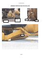
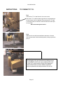
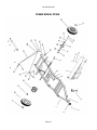
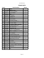
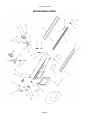
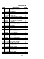
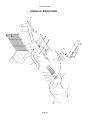
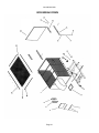
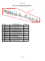
Vac 200-220-320
TABLE OF
CONTENTS
CONTENTS
TABLE
USER'S MANUAL
! CAUTION !
Note-1 (R.P.M.)
Note-2 (P.T.O.)
p.3
p.3
p.3
SAFETY PRECAUTIONS
p.4
IMPORTANT TO OPERATOR
p.4
MANUFACTURERS RECOMMENDATIONS
p.5
p.5
p.5
p.5
p.5
p.5
Storage
Transportation
Pick-up Module Adjustment
Using the manual suction hose
Cleaning
SETTINGS ACCORDING TO THE GROUND CONDITIONS
Important
Note-1
Note-2
PROBLEMS
p.6
p.6
p.6
p.6
p.6
p.6
p.6
p.6
p.6
Hydraulics on Vac doesn't work
Can't empty the box
Rubber finger breakage
Front roller damaging your grass
Daily
ROUTINE MAINTENANCE
p.7
p.7
GREASE POINTS ON VAC 200-220 & 320
p.8
HYDRAULIC CONTROL ON VAC 200-220 & 320
p.9
p.9
p.9
p.9
p.9
To empty box
Higher/Lower dock
Activate rubber fingers (axles)
Pick-up unit adjustment
INSTRUCTIONS ON HOW TO CONNECT P.T.O TO TRACTOR
Page 1
p.10
Vac 200-220-320
PARTS MANUAL
BLOWER BREAK DOWN
p.12
BLOWER PARTS
p.13 & 14
FRAME BREAK DOWN
p.15
FRAME PARTS
p.16
BROOM BREAK DOWN
p.17
BROOM PARTS
p.18
HYDRAULIC BREAK DOWN
p.19
HYDRAULIC PARTS
p.20
BOX BREAK DOWN
p.21
BOX PARTS
p.22
#6 P.T.O. BREAK DOWN
p.23
#6 P.T.O. PARTS
p.23
#6 P.T.O. SHIELD BRAKE DOWN
p.24
#6 P.T.O. SHIELD PARTS
p.24
Page 2
Vac 200-220-320
THERRIEN
Tech. Equip.
USER MANUAL
! CAUTION !
Note-1 For each use, please take note that the machine turns 4 to 6 gallons/minutes MAXIMUM
Note-2 Adjusting P.T.O. Drive Shaft Length
The length of the P.T.O. shaft is very important. If the P.T.O. shaft is too long, the transmission of the tractor or the
Therrien equipment can be damaged. When the overlap length of the tubes drops under 4" anytime, dangerous
situations may occur.
The length of the P.T.O. shaft changes when the blower is raised or lowered, when the Sweeper-Vac is
pulled around the corners or when the implements are used on different tractors.
The maximum recommended deflection for a standard P.T.O. shaft as used with the TS1 Debris Blower
is 30 degrees, therefore the lift/lower stop on the 3 point lift should be set accordingly. The Sweeper-Vac is
designed with a CV P.T.O. (#6) shaft, allowing for tighter operation in turns. In every applications, it is critical
that the P.T.O. should be shortened to the proper length.
To cut the standard P.T.O. from new, or to fit another tractor, proceed as follows.
1. Remove the P.T.O. shaft from tractor and implement.
2. (Dimension A) Measure the distance from the tractor P.T.O. stub shaft and the implement P.T.O. shaft,
groove to groove, at shortest point.(Raise and lower the attachment or pull the sweeper into a tight turn to
determine the shortest dimension.)
3. (Dimension B) Measure the length of the P.T.O. in its shortest position from lock pin to lock pin.
4. Split the P.T.O. in two pieces and remove safety covers from each end.
5. If required, shorten both tubes equally and shorten safety covers.
(Amount to shorten = Dimension B - Dimension A plus 2 inches)
6. Take apart all items, apply grease and put parts back together.
7. Re-install safety covers.
8. Fit to tractor and Therrien attachment and check the overlap tubes.
Never run machine with a damaged P.T.O. safety cover. Replace it first.
Steel tubes must overlap minimum 4" when P.T.O. is in the longest operating postion.
Page 3
Vac 200-220-320
SAFETY PRECAUTIONS
Correct operations and services are important for safe handling of this equipment
and the safety of the person operating it.
We have attempted to recommend adequate precautions against hazardous operating conditions , but it is
important to understand that Therrien Tech. Equipments Inc. cannot anticipate or list all operating conditions
against hazards. Anyone who operates this equipment should assure their own personal safety and the safety of
others, by becoming familiar with all controls and remaining alert to possible hazards.
Therrien Tech Equipments Inc. will not be responsible for any damages caused by the use of parts or services
obtained from sources other than from from authorized Therrien Tech Equipments Inc. dealers.
Follow the operating and maintenance instructions for best results and long life for your machines.
Observe the safety precautions and avoid accidents
IMPORTANT TO OPERATOR
This machine is designed for safe efficient operation. When leaving the manufacturer, the machine has all guards
shield and warning/operating decals firmly and correctly attached.
Before using this equipment, the operator must check thoroughly that all guards, shields and warning/operating
decals are in place.
Do not operate this equipment if any of the above safety items are missing,sing,
dameged
damaged
or improperly
or improperly
attached.
attached.
Before using this machine, the operator must read this manual to throughly familiarise himself with all
operating and safety procedures.
BE ALERT YOUR SAFETY IS INVOLVED
Page 4
Vac 200-220-320
MANUFACTURERS RECOMMENDATIONS
Storing the Vacuum
We recommend that the Vacuum should
be stored
be stored
in a dry
in aplace,
dry place
away
where
from itprecipitations.
will be safe from all kind of precipitations.
If this can not be done, take the screen off, located on top of Vaccum's box.
Transportation
The manufacturer recommends, when moving the Vacuum around, when not in use, that the owner follows these
directions:
The P.T.O. should be stopped
The Vacuum box should be lowered and closed
The manual suction hose should be replaced on it's bracket
Pick-up module adjustment
The adjustment of the efingers
fingershight
height
is made
is made
by 2
bywheels
22wheels
wheels
supporting
supporting
the pick-up
the pickmodule.
up module.
The finger tips are suppose
to lightly touch the ground. The floating pick-up is controled by 2 springs with chains and ajustable meshs to
adjust according to ground conditions. To ensure that the chains are well adjusted, attach tightly and release 3 meshs.
The pick-up module has 2 rubber bands, one in front and another in back, that are ajustable to control the air
that comes in. The rubber in front should be taken off in autumn to pick up leaves. The rubber in back should never
be taken off.
Using the Manual Suction Hose
The Manual Suction Hose is used to pick up the debris that are in places that the Vacuum cannot reach or pass.
To do so, take the hose off it’s bracket, then take the panel and slide it in the gap which is between the blower
and the broom. Pull the handle that is beside the lower hose and that will activate the manual suction hose.
Cleaning
The Vacuum most be properly cleaned after each use.
h use.
WeWe
recommend
recommend
thatusing
the user
pressurized
washes water.
the Vacuum with
pressurized-water.
pick-up module (3 doors)
Impeller (fan)
Interior of the box
Verify that no debris
debrisare
is stuck in the pick-up unit
unit.
Page 5
Vac 200-220-320
SETTINGS ACCORDING TO THE GROUND CONDITIONS
Note that the operating settings will vary with the range of conditions encountered in particular geographic
locations and climates. If there is very dry sand, loose soil, debris or very wet heavy leaves, twigs and clippings,
the following settings may be necessary to obtain the best permormance from the VAC 200-220 and 320.
Important
When engaging the P.T.O., do so with the R.P.M. at low speed i.e. approx. 800 engine R.P.M.
Engaging the P.T.O. at higher speeds may cause the drive belt to slip and burn.
Note-1
If conditions and/or type of materials or debris being picked-up requires more suction at the nozzle of the tractor,
P.T.O. speed can be increased from 540 R.P.M.
Note-2
Do not use the machine in reverse with the pick-up nozzle in the operating position.
PROBLEMS
Hydraulics on Vac doesn't work
Check hydraulic control on tractor (on & off)
Check hydraulic oil level on tractor
Check couplings on Vac hoses
Check control on Vac
Can't empty the box
Put all Vac hydraulic controls on neutral than activate control to empty box
If box is full of wet debris, empty half(1/2) of the box by hand
Rubber finger breakage
Check level of dock (too low)
Check u-bolts attaching rubber fingers (too tight)
Front roller damaging your grass
Vac is not leveled
Check level of dock (too low)
Page 6
Vac 200-220-320
ROUTINE MAINTENANCE
To have trouble-free operations on the machine, it is important to follow recommandations outlined below.
Check Daily
Check the tractor in accordance with the tractor manufacturers recommendations.
Check the presure of the Therrien Vac's tires - 15 p.s.i. (103 Kpa). Also Check for damage.
Check hydraulic hoses and connections for leaks.
Make a thorough visual check that all hardware, fittings, nuts, bolts, clamps, hoses, connections, tube
fittings and any electrical connections are correctly secured.
Check that all guards and shields are correctly secured and in place.
Check that all controls are clean, not damaged and ready to use.
Clean the machine with steam or with pressurized water regulary. This helps controlling operations, adds
to life of the machine, enables troublesome leaks to be detected and contributes to safety.
Refer to the lubrication guides on the following page to know where are the lubrication points.
Page 7
Vac 200-220-320
GREASE POINTS ON VAC 200-220 & 320
Grease two
wheels
Grease the
two sides of
the bearing
Grease
Grease
Grease
Page 8
Vac 200-220-320
HYDRAULIC CONTROL ON VAC 200-220 & 320
(This is the label on the hydraulic control.)
R
O
T
A
T
I
O
N
L
I
F
T
/
L
O
W
E
R
D
U
M
P
To empty box
Lift / Lower dock position
To activate rubber fingers (axles)
Hydraulic control on the tractor must be on. In some cases you may have to tie the control with a strap.
Pick-up unit adjustment
Rubber fingers must lightly touch the ground, (adjustments done
by two(2) wheels in the back on the pick-up module).
See diagram on the left. If the rubber fingers are too low, they
will easily break. You must also adjust the chains so that the
broom will follow the curves of the course.
In the fall, when picking up leaves, remove the front rubber.
Adjustment
Page 9
Vac 200-220-320
INSTRUCTIONS
INSTRUCTIONSTO
TOCONNECT
WELL CONNECT
P.T.O. THE P.T.O. TO TRACTOR
Fig-1
Connect the P.T.O. shaft from the Vac to the tractor .
Check the P.T.O. shaft so that the guards are not damaged and
the anti-rotation chain is attached. Ensure that the P.T.O. shaft
is correctly located on the tractor take-off shaft and located pins
are in position.
Broom must always be leveled.
Fig-2
When the Vac unit has been attached to the tractor, raise the
nose jack and stow in the horizontal position, locking in place the
jack pin.
! Caution !
When plugging in the quick disconnect couplings to the
tractor hydraulic control valve, the coupling valve must
be in the "off " power position. Refer to the operator's
manual of the tractor in use for details of hydraulic
remote couplers and the safe procedure for hook up.
Page 10
Vac 200-220-320
THERRIEN
Tech. Equip.
PARTS
MANUAL
Page 11
Vac 200-220-320
BLOWER BREAK DOWN
Page 12
Vac 200-220-320
BLOWER PARTS
Parts #
Parts Description
Amount
1
PA-0193
#6 HOMOCINETIC P.T.O.
1
2
PA-0019
5/16" NC X 3" GR 5 BOLT
1
3
PA-0020
5/16" NC NYLON INSERT LOCKNUT
2
4
PA-0056
3/8" NC X 1" BOLT
3
5
TV1-002-A PULLEY GUARD
1
6
PA-0019-2 5/16" NC X 3" BOLT
3
7
PA-0057
SK 1 1/2" HUB
1
8
PA-0058
3B 6.2 SD PULLEY
1
9
TV1-003-A 3/8" X 8" KEY
1
10
PA-0059
4
11
TV1-004-A WELDED AJUSTABLE PLATE
2
12
PA-0025
1/2" NC NUT
4
13
PA-0060
208-24 PILLOW BLOCK
2
14
PA-0061
5/8" NC X 2 1/2" BOLT
8
15
PA-0052
1/4"-28 STRAIGHT GREASE FIT
1
16
TV1-005-A CUP TUBE (SHORT)
1
17
TV1-006-A CUP TUBE (LONG)
1
18
,PA-0025-2 1/2" NUT
6
19
PA-0048
1/2" SPRING WASHER
6
20
PA-0050
1/2" FLAT WASHER
12
21
PA-0062
1/2" NC X 2 3/4" GR5 BOLT
6
23
PA-0205
PLASTIC CAP
1
24
PA-0064
3/8" NUT
20
25
TV1-008-A BLOWER CASE
1
26
TV1-009-A PROPELLER
1
27
PA-0065
1
28
TV1-010-A COVER
1
29
PA-0056-2 3/8" NC X 1" BOLT
20
30
TV1-011-A INGE PIN
1
31
PA-0137
1
32
TV1-012-A RUBBER PLATE
1
33
TV1-013-A RUBBER PLATE SUPPORT
1
34
TV1-014-A DOOR
1
5/8" NC NUT
3/4" NC X 2" GR12 BOLT
1/4" X 2" COTER PIN
Page 13
Vac 200-220-320
BLOWER PARTS (CONTINUE)
Parts #
Parts Description
Amount
35
PA-0068
8" DIA. X 150" FLEXIBLE HOSE
36
TV1-015-A FLEXIBLE HOSE SUPPORT
1
37
PA-0045
5/16" NC X 2" HEX. BOLT
1
38
TV1-062
HANDLE
1
39
PA-0020
5/16" NC NYLON INSERT LOCKNUT
1
40
PA-0070
MIKALOR COLLAR #201-213
1
42
PA-0071
UCP 211-32 PILLOW BLOCK
2
43
TV1-016-A PULLEY SHAFT
1
44
TV1-017-A 1/2" X 1/2" X 3 1/2" KEY
1
45
PA-0072
2
46
TV1-018-A GUARD
1
47
TV1-019-A PROPELLER SHAFT
1
48
PA-0073
3B 13.6 SK PULLEY
1
49
PA-0074
SD 2" HUB
1
50
PA-0075
B53 BELT
3
51
TV1-020-A CLAMPING HANDLE
1
52
PA-0076
1/2" NC X 3" BOLT
1
53
TV1-021-A VALVE SUPPORT
3
54
TV1-022-A VALVE TUBE
1
55
PA-0069
5/16" NC X 2 3/4" BOLT
2
56
PA-0026
1/2" NC X 2 1/2" BOLT
1
3/8" NC X 3/4" HEX. BOLT
Page 14
1
Vac 200-220-320
FRAME BREAK DOWN
Page 15
Vac 200-220-320
FRAME PARTS
Parts #
Parts Description
Amount
1
TV1-023-A FRAME
1
2
TV1-024-A FRAME ATTACH
1
3
PA-0033
5/8" NC X 2 3/4" BOLT
4
4
PA-0077
5/8" NC JAM NUT
4
5
PA-0078
JACK
1
6
PA-0050
1/2" WASHER
4
7
PA-0079
CYLINDER PIN
1
8
PA-0067
1/8" "R" PIN
1
9
PA-0080
5000 PDS SHAFT
2
10
PA-0081
SCA 02583 OIL SEAL
2
11
PA-0082
LM 603049 BEARING CUP
2
12
TV1-026-A 1/4" STEEL CABLE
1
13
PA-0083
1/4" SLEEVE (CABLE TIGHTNER)
3
14
PA-0084
LM 48548 BEARING CUP
2
15
PA-0085
1" NC CASTLE NUT
2
16
PA-0086
H-5000 DUST CAP
2
17
PA-0087
1/2" NF X 1 1/4" WHEEL NUT
12
18
PA-0088
COMPLETE WHEEL 26 X 12,00-12 8 PLY
2
19
PA-0089
3/16" DIA. COTER PIN
2
20
PA-0090
1" I.D. WASHER
2
21
PA-0091
LM 48548 BEARING CONE
2
22
PA-0092
5000 PDS COMPLETE HUB
2
23
PA-0093
LM 603049-N BEARING CONE
2
24
TV1-027-A CABLE PULLEY SUPPORT
2
25
TV1-028-A CABLE PULLEY
5
26
PA-0064
2
27
TV1-029-A STEEL SPACER
2
28
PA-0094
3/8" NC X 2 1/2" BOLT
1
29
PA-0083
1/4" SLEEVE (CABLE TIGHTNER)
1
30
PA-0095
WHEEL RIM
1
31
PA-0096
RUBBER VALVE
1
32
PA-0097
TIRE
1
3/8" NC NUT
Page 16
Vac 200-220-320
BROOM BREAK DOWN
Page 17
Vac 200-220-320
BROOM PARTS
Parts #
Parts Description
Amount
1
PA-0098
5/16" NC X 2 1/2" BOLT
8
2
TV1-030-A FRONT RUBBER SUPPORT
1
3
TV1-031-A FRONT RUBBER
2
4
TV1-033-A ACCESS DOOR
2
5
TV1-034-A FRONT ROLLER
3
6
TV1-035-A 1/2" NC X 7" BOLT
2
7
PA-0056
2
8
TV1-036-A CENTRAL AXLE
9
PA-0100
1/4" NC NYLON INSERT LOCKNUT
10
PA-0101
UCFL205-16
11
PA-0050
1/2" WASHER
13
PA-0102
1/4" U-BOLT
14
TV1-037-A RUBBER FINGER WITH TIP
15
TV1-038-A REAR RUBBER
1
16
TV1-063-A SPRING PIN
2
17
PA-0202
2
18
TV1-039-A 15 MESHS CHAIN
2
19
PA-0103
9" EXTENTION SPRING
2
20
PA-0025
1/2" NC NYLON STOP NUT
2
21
PA-0201
1/2" X 6 1/2" NC BOLT
2
22
TV1-040-A WHEEL SUPPORT
2
23
PA-0105
3/4" NC X 6" BOLT
2
24
PA-0064
3/4" DIA. WASHER
2
25
PA-0106
9" DIA. X 3,5 KENDA WHEEL
2
26
TV1-065-A ADJUSTMENT PANEL
1
27
PA-0200
1
28
TV1-041-A PICK UP FRAME ASSEMBLY
1
29
TV1-042-A CUP TUBE WITH FITTING
1
30
PA-0107
900 X 1/8" GREASE FITTING
1
31
PA-0108
40B 29 SPROCKET
1
32
TV1-043-A SPROCKET GUARD
1
33
TV1-044-A #40 CHAIN WITH MESHS
1
34
TV1-066-A 2" DIA. X 1" TENSIONER
1
35
PA-0110
1
36
TV1-045-A SIDE LOCK PANEL
1
37
TV1-046-A PICK UP ADAPTOR
1
1/2" NC NYLON INSERT LOCKNUT
1
ANTIFRICTION BEARING
260
2
2
130
130
3/4" OD COMPRESSING SPRING
1/2" NC BOLT
40 B 48 SPROCKET
Page 18
Vac 200-220-320
B
A
HYDRAULIC BREAK DOWN
Page 19
Vac 200-220-320
HYDRAULIC PARTS
Parts #
Parts Description
Amount
1
PA-0111
1/2" MALE QUICK DISCONNECT
3
TV1-047-A 1/2" DIA.4' LG ASSY HYDRAULIC HOSE
2
4
PA-0113
REMOTE CONTROL STICK
3
6
PA-0115
849-FSO-08X08 COPLER
2
7
PA-0116
3 REMOTE CONTROL VALVE
1
8
PA-0117
848-FSO-06X08 UNION
1
9
PA-0118
848-FSO-06X06 UNION
5
10A
TV1-048-A 3/8"DIA. 14'6" HYDRAULIC HOSE KIT
1
10A
TV1-067-A 1/2"DIA. 14'6" HYDRAULIC HOSE KIT
1
10B
TV1-049-A 3/8"DIA. 15' HYDRAULIC HOSE KIT
2
10C
TV1-050-A 3/8"DIA. 12'3" HYDRAULIC HOSE KIT
1
10C
TV1-051-A 3/8"DIA. 14'11" HYDRAULIC HOSE KIT
1
12
PA-0119
848-FS-06X06 UNION
2
13
PA-0120
12" X 2" DIA. CYLINDER
1
16A
PA-0121
849-FSO-06X06 UNION
1
16B
PA-0118
848-FSO-06X06 UNION
1
17
PA-0122
30" X 4" DIA. CYLINDER
1
18
PA-0123
MLHPQ100 C4C HYDRAULIC MOTOR
1
19
PA-0124
60UB-10X08 UNION
2
20
PA-0125
1/2" FEMALE QUICK DISCONNECT
1
21
PA-0204
24SA-08 UNION
2
Page 20
2
Vac 200-220-320
BOX BREAK DOWN
9A
B
HJKH
Page 21
Vac 200-220-320
BOX PARTS
Parts #
Parts Description
Amount
1
TV1-051-A BOX ASSEMBLY
1
2
PA-0128
1
3
TV1-052-A 4'4"GLASS WINDOW RUBBER
1
4
TV1-053-A VACUUM PANEL
1
6
TV1-054-A PANEL STRAP
2
7
PA-0129
4
8
TV1-055-A 5/8" X 1" NEOPRENE GASKET
1
9A
PA-0131
1/4" NC NYLON JAM NUT
3
9B
PA-0136
1/4" NC X 1 3/4" HEX. BOLT
2
10
TV1-063-A SWIVEL ROD
2
11
TV1-056-A 1/4" X 36" DOOR CABLE
2
12
TV1-057-A RETAINED CABLE STRAP
2
13
PA-0083
4
14
TV1-058-A DOOR LEVER
2
15
TV1-059-A DOOR HINGES
2
16
PA-0132
3/8" X 1 1/4" BOLT
2
17
PA-0133
3/8" NC NYLON JAM NUT
1
20
TV1-060-A DOOR ASSEMBLY
1
23
PA-0135-1 SCREEN FOR VAC-200
1
23
PA-0135-2 SCREEN FOR VAC-220
1
23
PA-0135-3 SCREEN FOR VAC-320
1
24
TV1-061-A SIDE SCREEN SUPPORT
2
25
PA-0028
20
26
TV1-062-A FRONT OR REAR SCREEN SUPPORT
2
27
PA-0065
2
GLASS WINDOW
3/8" NC X 1 1/2" BOLT
1/4" CABLE CLIPS
1/4" NC X 2 1/4" BOLT
3/4" NC X 3" BOLT
Page 22
14
Vac 200-220-320
#6 P.T.O.(CV) BREAK DOWN & PARTS
10
12
8
5
9
11
Parts #
Parts Description
Amount
1
PA-0182
#6 P.T.O. CROSS & BEARING KIT
1
2
PA-0183
#6 P.T.O. DOUBLE YOKE
1
3
PA-0184
#6 P.T.O. OUTER TUBE YOKE
1
4
PA-0185
#6 P.T.O. OUTER ELASTIC PIN
1
5
PA-0186
#6 P.T.O. INNER ELASTIC PIN
1
6
PA-0187
#6 P.T.O. INNER YOKE TUBE
1
7
PA-0188
#6 P.T.O. CROSS & BEARING KIT
1
8
PA-0189
#6 P.T.O. OUTER TUBE
1
9
PA-0190
#6 P.T.O. INNER TUBE
1
10
PA-0191
#6 P.T.O. TRACTOR COLLAR
1
11
PA-0192
#6 P.T.O. 1 1/2" OUTER YOKE
1
12
PA-0193
COMPLETE #6 P.T.O.(CV)
1
Page 23
Vac 200-220-320
#6 P.T.O. (CV) SHIELD PARTS
6
2
4
1
3
5
Parts #
Parts Description
Amount
1
PA-0194
#6 P.T.O. PLASTIC CASE
1
2
PA-0195
#6 P.T.O. PLASTIC BOLT
6
3
PA-0196
#6 P.T.O. RING
1
4
PA-0197
#6 P.T.O. SECURITY CHAIN
1
5
PA-0198
#6 P.T.O. PLASTIC CASE KIT W/ASSEMBLY
1
6
PA-0199
#6 P.T.O. COMPLETE PLASTIC SHIELD
1
Page 24
Vac 200-220-320
Fabricated by: Therrien Technical Equipments
Phone : (819) 392-2846
Fax : (819) 392-2888
Saint-Nazaire, PQ
E-mail : [email protected]
Web Site : www.atherrien.com
Distributed by:
Page 25