1
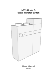
i - STS
19 inch Rack mount
S T A T I C
i
T R A N S F E R S W I T C H E S
Model i-STSBs/M – 1P2
– STS Manufacturing is a subsidiary of STATIC POWER PTY. LTD.
ABN 42 101 765 913
i-STS Manufacturing
This manual refers to: Model
STATIC TRANSFER SWITCH
i-STS32Bs-1P2
Electrical Specifications
Rating
Voltage Rating
Frequency
Permissible Voltage Distortion
Fault rating
Protection
Type
Manufactured
Warranty
Maximum Ambient
Dissipation
IP Rating*
Maintenance Bypass
Bypass Interlock
Neutral Rating
Fault Current Setting
Parallelable
Overload Ratings
Fault Capacity
Synchronization Window
Break Time
Sensing Time
LAN Browser
Modbus TCP
Set-up
Remote i/o
Device Ratings
dv/dt
Environmental
Storage
Operating
Humidity
Altitude
Audible Noise
Static Transfer Switch i-STS
32 Amperes RMS
230 V ± 20%
50 Hz ± 10%
10% THDV
2 kA, 10 msec
100 Ampere Fuses
Thyristor
1st December 2005
24 Months (Return Basis)
40 oC
< 60 Watts @ 32 A RMS
IP20
Integral CAM 2 Pole overlapping
Yes – Electrical Common
32 Amperes
5 times rated peak (pre-set)
No
36 Amps 60 minutes (120 %)
50 Amps for 10 seconds (150 %)
125 Amps for 1 sec
2,000 Amps (10 msec).
10 deg. (Settable 5 – 180 deg)
< ¼ cycle
< 1 msec
No
No
LCD
Contacts (50 V DC, 1 Ampere n/c)
120Amps,1800Volts,100,000 A2S
1000 v/usec
* Not for outdoor use.
0 – 70 oC
0 – 40 oC
5 – 90 % non condensing
1000 m no de-rating
50 dB(A) @ 1.5 metres
2
i-STS Manufacturing
Index
STATIC TRANSFER SWITCH
SPECIFICATIONS
1.
2.
3.
4.
5.
6.
7.
8.
9.
10.
11.
12.
13.
14.
15.
16.
OPERATIONAL DESCRIPTION
CONTROLS
LCD INTERFACE
LED INTERFACE
REAR PANEL CONTROLS
REAR PANEL USER ACCESS
SETTINGS AND ADJUSTMENTS
INSTALLATION
SET-UP AND COMMISSIONING
MAINTENANCE & BYPASS OPERATION
INTERPRETATION OF EVENT LIST
SET-UP / CALIBRATION & ADJUSTMENT
FAULT DIAGNOSIS & MAINTENANCE
DRAWINGS & SCHEMATICS
PARTS LIST
WARRANTY - CONTACT & SERVICE INFORMATION
Static Transfer Switch i-STS
3
i-STS Manufacturing
STATIC TRANSFER SWITCH
1.
OPERATIONAL DESCRIPTION
A Static Transfer Switch, (STS) provides your critical load or single chord
(single supply), technology equipment with an alternative supply source,
thus increasing and improving distribution reliability and availability.
i-STSB rack mounted static transfer switches are manufactured as a two
pole. Both the active conductor and the neutral are switched. Thyristors
are used to undertake the switching process. These are many times faster
and more rugged and reliable than their electromechanical equivalents.
Supply 1
Supply 2
Load
Fig. 1.
The Static Transfer Switch continuously monitors the supply sources and
should the supply presently connected to the critical load fail or
degenerate to not be useable by the critical load the critical load is
automatically and transparently transferred to the alternate source.
This switching process is undertaken as a break before make. The break in
the supply transition is so short that it is not seen to the critical load. This
is preferable to a make before break (or overlapping) change-over because
when the two supplies are different and connected together large and
unpredictable currents would flow between the sources degenerating both
supplies and therefore the supply to the critical load.
This model - i-STSB, Static Transfer Switches can not be ganged or inter
connected to form a multi-pole arrangement.
Static Transfer Switch i-STS
4
i-STS Manufacturing
2.
CONTROLS
STATIC TRANSFER SWITCH
Maintenance Controls
If you have an i-STSBsM model than you have a Maintenance Bypass
switch located on the front panel.
N
This is a make-before-break transition between the STS output and either
incoming supply 1 or 2 depending on the direction that you turn the
switch. The user should only operate the switch to the supply that is
indicated by the STS as being selected. E.g. if the STS is on supply 1 then
only use the bypass switch to go to supply 1. The switch has provision for
locking (using a pad-lock) into any one of the tree positions, (supply 1,
normal (depicted as “N”), and supply 2).
Normally the switch is left in the “N” position.
The switch is used only for maintenance purposes when the STS is faulty
and requires maintenance and the STS module needs to be removed.
The two incoming protection isolators on the front panel adjacent to and
to the right of the Maintenance bypass switch do not isolate power to the
load when the maintenance Bypass Switch is in position 1 or position 2.
These isolators will remove power to the static portion of the Static
Transfer Switch when in normal operation and should not be operated
unless undertaking maintenance or in an emergency. With the STS
removed there is a break when using the maintenance bypass switch from
position 1 to 2 (or vica versa) through the “N” position.
Static Transfer Switch i-STS
5
i-STS Manufacturing
STATIC TRANSFER SWITCH
Front Panel Controls
The front panel as depicted only has one control pushbutton, “TRANSFER”.
This toggles between the two supply sources. Throughout this manual they
will be referred to as “Supply 1” and “Supply 2” respectively. The output
for the critical load will be referred to as “Supply 3”.
The LCD version of the control panel has two additional screen information
selection control pushbuttons; however, these do not perform any
operational function.
There are other user controls; however, these reside on the back panel and
/ or via the HLI interfaces. These additional controls are not required for
normal operation.
Depiction may vary depending on model.
Static Transfer Switch i-STS
6
i-STS Manufacturing
3. LCD INTERFACE
STATIC TRANSFER SWITCH
A red LED “ALARM” is used to indicate a non normal condition or state. The
LCD will indicate the nature of the abnormality.
Operation through the LCD hierarchy allows screen function selection
using the
key. Where additional information is available on subsequent
screens, such as Event History and Set-up then these are
accessed using the
key.
Event List (100 events)
Use
to view more
Load Power Quality Analyser
(via - password 000)
Current => ………. waveform
Voltage => _____ waveform
Static Transfer Switch i-STS
7
i-STS Manufacturing
STATIC TRANSFER SWITCH
For example to set the time from the Configuration screen press the
key to vary
key. A cursor will then highlight the variable field. Press the
the field.
Holding the key for more than 2 seconds will allow a fast scroll. When set
key to move to the next field and repeat
to the desired value use the
the process.
To affect a transfer to the alternative supply manually the user must press
and hold the TRANSFER pushbutton for at least 2 seconds.
Static Transfer Switch i-STS
8
i-STS Manufacturing
STATIC TRANSFER SWITCH
This diagram shows the available options and how to navigate them:
STATUS shows which supply (1 or 2) is connected the critical load.
This supply also indicates any pending alarm condition.
VARIABLES indicates the input and output electrical parameters.
POWER QUALITY assessment is made by visually showing a snap shot of the voltage
and current waveforms. Crest factor and a harmonic analysis of the waveforms
provide a power quality estimate for the load.
EVENT LIST Any changes of state and or alarms generated are recorded in real time
in a circular 100 event buffer.
A PASS CODE is required to gain entry to the SETTINGS, DIAGNOSTICS,
CONFIGURATION and CALIBRATION screens. (3 levels of access allow
changing of values within recommended limits, a second level allows
setting without limits and a third level allows access to other not normally
used access points / values).
RESERVED may contain specific options and configurations applicable only
to your units.
Static Transfer Switch i-STS
9
i-STS Manufacturing
STATIC TRANSFER SWITCH
Additional set-up / configuration and calibration screens are accessible
only by entering the correct passcode.
It is important that the user understands the consequences of the changes
made within these menus as unpredictable and incorrect operation may
result if settings are incorrectly set.
Incorrect setting is not covered by the warranty. Refer to Section 7.
Static Transfer Switch i-STS
10
i-STS Manufacturing
4.
LED INTERFACE
STATIC TRANSFER SWITCH
LED front panel controls consists of only one manually operated transfer
switch pushbutton. The user must press and hold for At least 2 seconds to
affect a manual transfer to the alternate supply. Note that manually
transferring overrides the preferred source selection at the rear of the
unit.
The LED mimic shows a limited number of operational states. These are as
outlined below. If the Alarm LED is “ON” and the STS condition is not
immediately able to be determined from the LED indicators then the user
may use the HLI port or voltage free contact status at the rear of the STS
to further interrogate the unit.
SUPPLY 1
SUPPLY 2
1
2
SYNC
LOAD
Green -> Available
Green Flashing -> Not within Specification
Red -> Failed
Green -> Available
Green Flashing -> Not within Specification
Red -> Failed
Green -> On Line (connected to critical load)
Red -> Not on (NOT connected to critical load)
Green -> On Line (connected to critical load)
Red -> Not on (NOT connected to critical load)
Green -> In synchronism
Green Flashing -> Occasionally in Synchronism
Red -> Not in synchronism
Green -> Normal
Red -> Alarm (flashing) -> Overloaded
5. REAR PANEL CONTROLS
Static Transfer Switch i-STS
11
i-STS Manufacturing
STATIC TRANSFER SWITCH
\
The main power flows through the power plugs on the left side of the
removable RHS module of the static transfer switch, (Note that terminal
arrangements may differ for the model supplied. Please refer to the
schematic details at the rear of this manual for specific connection
information).
Some models have an Electrical Interlock connection between the
Maintenance Bypass and the STYS. This is located in the vicinity of the LAN
connection. Ensure that the Maintenance Bypass electrical interlock plug is
inserted and pushed fully home.
3-Phase and Parallel Bus connection points omitted on single phase only
units.
Static Transfer Switch i-STS
12
i-STS Manufacturing
STATIC TRANSFER SWITCH
PREFERRED SOURCE SELECTION (pre-set)
0
1
2
No preferred source
Supply 1 is the preferred source. If STS is forced to
automatically transfer the critical load to the alternate
(Supply 2) source the STS will automatically transfer
back to Supply 1 when again within tolerance and a pre-set
settling delay.
Supply 2 is the preferred source. If STS is forced to
automatically transfer the critical load to the alternate
(Supply 1) source the STS will automatically transfer back
to Supply 2 when again within tolerance and pre-set settling
delay.
CONTROL OVERRIDE (CAUTION for Maintenance ONLY)
0
Normal – Automatic
1
Control Override -> Supply 1 is forced to supply the critical load
directly overriding any internal control logic.
2
Control Override -> Supply 2 is forced to supply the critical load
directly overriding any internal control logic.
3-PHASE BUS
Parallel Bus
Static Transfer Switch i-STS
Not Available in this model
Not Available in this model
13
i-STS Manufacturing
6.
REAR PANEL USER ACCESS
STATIC TRANSFER SWITCH
CAUTION
The power cabling should not be run adjacent to user
controls. Separate these control cables from power circuits
by at least 300 mm. The control signals are distance limited
to 30 metres.
All output relays contacts are rated for 50 V DC 1 Ampere
(Not
230 V AC rated)
User Remote Inputs (Voltage free contact closure controllers only)
COMM -> Common return
a -> Transfer to Supply 1
b -> Transfer to Supply 2
c -> Fire Stop (Causes both Switches to go off – loss of output)
User Relay Outputs
Relays are normally closed and held open in OK state (closed contact
represents the alarm state).
A
B
C
D
E
F
G
->
->
->
->
->
->
->
General Alarm
Not in Synchronism
Supply 1 OK
Supply 2 OK
ON Supply 1
On Supply 2
Overloaded
RS232 PORT
All settings and calibrations can be performed through the front panel.
LAN
See LAN Supplement Manual
Static Transfer Switch i-STS
14
i-STS Manufacturing
STATIC TRANSFER SWITCH
7. SETTINGS AND ADJUSTMENTS
Screen 1
Basic password “000”
Settings Password 123 for access level that allows adjustment between the
parameters shown only.
Within the Settings menu’s there are two setting ranges
One for user manually initiated transfers using the front panel push
button “Man”
And
Settings that are used under fault detected conditions, “Auto”
It is important that the Auto Settings be set wider than the normal
operating source limits, (e.g. wider than the UPS capability).
Otherwise you may experience unstable operation of the STS
responding to conditions that are normal for the supply.
In general the STSs function is to transfer to the alternate source
when the online source becomes unavailable. The STS should not be
considered as protection against power quality from the source.
There are 5 screens of settings and calibration.
• Screen 1
Comment
% from nom 105 – 125 % (120 %)
% from nom 0 – 95 % ( 70 %)
% from nom 105- 120% (110 %)
% from nom 0 – 95% ( 90 %)
1 – 3 sec (1.5 sec)
1 – 180 deg (10 deg)
1 -1 80 deg ( 30 deg)
Static Transfer Switch i-STS
15
i-STS Manufacturing
STATIC TRANSFER SWITCH
The column to the right shows the variation setting limits for each
parameter.
Set describes the parameter for adjustment:
S1 S/S Hi (Supply 1 Steady State High)
Averaging time constant for this parameter is defined by
“S/S Pause” typically 1.5 seconds.
Set as a percentage from nominal – Default setting 120%
S1 S/S Lo (Supply 1 Steady State Low)
Averaging time constant for this parameter is defined by
“S/S Pause” typically 1.5 seconds.
Set as a percentage from nominal – Default setting 70%
S2 S/S Hi (Supply 2 Steady State High)
Averaging time constant for this parameter is defined by
“S/S Pause” typically 1.5 seconds.
Set as a percentage from nominal – Default setting 120%
S2 S/S Lo (Supply 2 Steady State Low)
Averaging time constant for this parameter is defined by
“S/S Pause” typically 1.5 seconds.
Set as a percentage from nominal – Default setting 70%
S/S Pause (steady State Averaging time constant)
This is the time that the steady state values need to be outside the
limit values before a fault condition is determined to be true.
NOTE adjustment may be required to the steady state values if the
source supply voltages are above or below nominal, generally the
setting should be set to 120% of the value of the supply source, in
the range of 105-125% setting too close a limit to the actual
operating Steady State voltage may cause erratic Static Transfer
Switch operation.
Also setting the averaging time to too small a value (< 1 sec) may
cause erratic operation.
Static Transfer Switch i-STS
16
i-STS Manufacturing
STATIC TRANSFER SWITCH
Phase Norm setting limits 0 – 180 degrees default 10 degrees
Phase margin in electrical degrees for which a normal user initiated
no-break manual transfer can be achieved. Pushbutton requests
when the angle is greater than that shown will be ignored. If
however, the supplies are continually varying because the sources
are operating at different frequencies and as long as the difference
frequency is within 5% (2.5Hz) pressing and holding the pushbutton
for 10 seconds will latch the request which will be processed when
the two supplies come within the setting limit where the transfer
request will then be activated. If however, the supplies do not come
back into synchronism within 60 seconds the user latching request
will be cancelled. Although the setting limit can be set from 0 to
180 degrees the consequence of transfers when not in synchronism
may result in a non seamless transfer for the critical load.
Ferromagnetic devices such as transformers will saturate and draw
large current when out of synchronism transfers are undertaken.
The effect on some switchmode power supplies is also unknown. The
user should consult with the equipment manufacturer to ensure that
damage does not result from out of synchronisation transfers and
what their recommended synchronization limits are.
When set to “0” disables the transfer pushbutton operation.
If the programmed value in the “Auto” column is exceeded no action
takes place. Refer to “Phase Fault”
Phase Fault (setting limits from 0 to 180 degrees electrical).
Automatically initiated transfers due to supply source / output
supply faults when a transfer to the alternate source is necessitated.
The recommended default of 30 degrees. Up until this value
transfers that are initiated from the system (except manually) will
occur without a break. Once the displacement between the two
phases is more than this value (30 degrees) a break as defined by
“Phase Break” is inserted. Settings to 180 degrees are possible.
The application of inserting a break when the two supplies are
significantly out of synchronism has been established to prevent the
inadvertent damage to equipment, tripping of protection devices or
Static Transfer Switch i-STS
17
i-STS Manufacturing
STATIC TRANSFER SWITCH
opening of fuses that could result from overfluxing of transformers,
misfiring of switch mode power supplies. The philosophy is that it is
better to allow the equipment to shutdown orderly and re-power up
normally rather than under fault conditions. The minimal value
would be considered at 50 msec.
Phase Break Setting of “0” insert no-break 10 – 150 msec with
resolution of 10 msec. These are typical break insertion times,
additional time would be added as a result of thyristor turn-off
delays.
Static Transfer Switch i-STS
18
i-STS Manufacturing
STATIC TRANSFER SWITCH
Screen 2
% from nom 108– 135% (130 %)
% from nom 92 – 0 % (65%)
% from nom 108– 135% (135 %)
% from nom 92 – 135% ( 65 %)
1 – 100 msec (1 = 330 usec)
0 – 300 sec (5 sec)
0 – 5 (0 inhibits), (3)
S1 fast Hi (Supply 1 Transient High)
Transient time constant for this parameter is defined by
“Transient over-sampling time constant 2 x 330 Micro Sec”
Set as a percentage from nominal – Default setting 130%
S1 fast Lo (Supply 1 Transient Low)
Transient time constant for this parameter is defined by
“Transient over-sampling time constant 2 x 330 Micro Sec”
Set as a percentage from nominal – Default setting 65%
S2 fast Hi (Supply 2 Transient High)
Transient time constant for this parameter is defined by
“Transient over-sampling time constant 2 x 330 Micro Sec”
Set as a percentage from nominal – Default setting 130%
S2 fast Lo (Supply 2 Transient Low)
Transient time constant for this parameter is defined by
“Transient over-sampling time constant 2 x 330 Micro Sec”
Set as a percentage from nominal – Default setting 65%
Fast Pause (Transient over-sampling time constant)
This is the transient over-sampling quantity / times that the values
need to be outside the limit values before a fault condition is
determined to be true.
ReTx Pause
Operates only when originally on preferred source and when
preferred source has been set and an automatically initiated
Static Transfer Switch i-STS
19
i-STS Manufacturing
STATIC TRANSFER SWITCH
transfer to the stand-by alternate supply as a result of a source fault
occurs. This parameter defines the delay before a re-transfer back
to the original preferred source occurs after the fault has been
cleared and the source has returned to normal steady state
conditions.
This parameter is usually set to 5 seconds. If set to too small a value
an unstable condition could result because the source response time
is similar to the re-transfer time and the source has not been given
enough time to recover.
Preferred source is set to either Supply 1 preferred or supply 2
preferred or no preferred source using the slide switch on the user
controls mounted at the rear of the STS. Also see preferred
software setting to follow.
ReTx Tries
This setting refers to the number of times that an transfer back to
the preferred source will be attempted. A lock out results after this
but is re-set on new fault alarm condition.
A setting of “0” inhibits re-tries even when preferred source is set a
transfer when initiated will not result in a transfer back to the
preferred.
NOTE adjustment may be required to the Transient values if the
source supply voltages are distorted or above or below nominal.
Setting too close a limit to the actual operating Steady State voltage
may cause erratic Static Transfer Switch operation.
Also setting the over sampling time to too small a value (1) may
cause erratic operation.
Static Transfer Switch i-STS
20
i-STS Manufacturing
•
STATIC TRANSFER SWITCH
Screen 3
% from nom 108-135%(125%)
% from nom 80-95%(65%)
% from nom 108-135%(120%)
% from nom 80-95% (80%)
Low current threshold (10%)
Overload time (min) @ 110 &125 % Overload
Overload time (min) @ 150 & 200 % Overload
S3 /Output Steady State High % from nom 108-135%(125%)
Averaging time constant for this parameter is defined by
“S/S Pause” typically 1.5 seconds.
Set as a percentage from nominal – Default setting 125%
Should always set this parameter wider than the S1 & S2 steady stat
high threshold. This will ensure that when there is a problem with
S1/S2 event list will report correctly. S3 sensing is provided as
redundant sensing for on line source S1 or S2 and in case of internal
thyristor triggering fault. Operation is to transfer to the alternative
source.
Output Steady State Low % from nom 0-95%(65%)
Averaging time constant for this parameter is defined by
“S/S Pause” typically 1.5 seconds.
Set as a percentage from nominal – Default setting 65%
Should always set this parameter wider than the S1 & S2 steady stat
low threshold. This will ensure that when there is a problem with
S1/S2 event list will report correctly. S3 sensing is provided as
redundant sensing for on line source S1 or S2 and in case of internal
thyristor triggering fault. Operation is to transfer to the alternative
source.
Output transient High % from nom 108-135%(120%)
Transient time constant for this parameter is defined by
“Transient over-sampling time constant 2 x 330 Micro Sec”
Set as a percentage from nominal – Default setting 133%
Static Transfer Switch i-STS
21
i-STS Manufacturing
STATIC TRANSFER SWITCH
Should always set this parameter wider than the S1 & S2 transient
high threshold. This will ensure that when there is a problem with
S1/S2 event list will report correctly. S3 sensing is provided as
redundant sensing for on line source S1 or S2 and in case of internal
thyristor triggering fault. Operation is to transfer to the alternative
source.
Also transient limits should be set outside steady state limits.
Output transient Low % from nom 80-95% (80%)
Transient time constant for this parameter is defined by
“Transient over-sampling time constant 2 x 330 Micro Sec”
Set as a percentage from nominal – Default setting 60%
Should always set this parameter wider than the S1 & S2 transient
high threshold. This will ensure that when there is a problem with
S1/S2 event list will report correctly. S3 sensing is provided as
redundant sensing for on line source S1 or S2 and in case of internal
thyristor triggering fault. Operation is to transfer to the alternative
source.
Also transient limits should be set outside steady state limits.
Low current threshold (0%)
Normally set to “0”, defines the minimum vale for units load. The
units supplied have an output load resistor located in the
maintenance bypass enclosure. Otherwise set to 2% if testing unit
without being plugged into maintenance bypass (e.g. for testing).
Setting to non zero value ill disable thyristor open circuit and short
circuit detection until after the threshold has been reached.
Overload time (min) @ 110 &125 % Overload
Exceeding the overload limits of 110 % for greater than 60 minutes
OR 125 % for 20 Minutes will not affect the critical load and no
switching occurs. It is intended as a warning that the STS is
overloaded. Failure to reduce the load will cause semiconductor
failures.
Static Transfer Switch i-STS
22
i-STS Manufacturing
STATIC TRANSFER SWITCH
Consult manufacturer before setting to higher values to ensure that
the unit will operate safely without failure or overheating.
Overload time (min) @ 150 & 200 % Overload
Exceeding the overload limits of OR 150% for 10 Minures
OR 200% for 1 Minute will not affect the critical load and no
switching occurs. It is intended as a warning that the STS is
overloaded. Failure to reduce the load will cause semiconductor
failures.
Consult manufacturer before setting to higher values to ensure that
the unit will operate safely without failure or overheating.
Xfer Timer Usually left at “0” settable 0 to 1275 (increments of 15
minutes per increment.
Setting of “0” disables function
After the set period the STS will undertake a test transfer to the
alternate source. After a delay the load will be returned to the
original source. This function is used to test functionality and
protections within the STS.
Static Transfer Switch i-STS
23
i-STS Manufacturing
STATIC TRANSFER SWITCH
Screen 4
Deg from 50Hz +/- 9Hz ( 5Hz)
1 or 2 or 0 (none) – ( 0)
S, F or B ( S)
150 – 1500 % ( 800 %)
0 None, 1Current, 2Temp(0)
123
1 toggle,2 1&2,3 no STOP (2)
Hz
Allowable frequency tolerance for Supply 1 and Supply 2. Exceeding
these limits will cause a transfer to the alternate source. E.g. a
setting of 5Hz is the default. Settings of greater than 5 Hz are not
recommended.
Settings for Man will inhibit user manual transfers when greater than
the setting.
Preferred (0)
Similar to the rear panel section of preferred source. This is useful if
access to the rear panel preferred source selection is impaired. The
rear panel slide switch overrides any settings on this screen. To
ensure operation the rear panel slide switch needs to be in the “0”
centre position. In all other respects the control operates as per the
rear panel slide switch.
Mode (s)
‘s’ refers to standard mode. All STSs supplied “B type” are standard
thyristor STSs. The selections B and F refer to interrupting capability
of some models. In this case the switch can be configured to operate
in the standard thyristor mode (current zero turn-off) when
manually transferred by the user from the front panel to either
current blocking or fast interrupt & transfer.
Peak I (Unable to set through user interface)
This is the value of peak load current that is used to inhibit a
transfer to the alternate source even if the voltage is adversely
affected. This setting is used to prevent the transfer of a load fault
Static Transfer Switch i-STS
24
i-STS Manufacturing
STATIC TRANSFER SWITCH
to the alternate source. This is necessary when supplied from two
UPSs so that the both UPSs are not affected by the load fault. The
STS remains on the original source even if this causes loss of supply
to the source. The system will automatically reset to normal mode a
few seconds after the return of a good voltage on the source and the
current falling below the threshold (e.g. the fault ahs been cleared).
On the equipments supplied this has been pre-set in hardware to 200
– 250 Amperes peak and cannot be changed by the user through this
menu option.
Fan Mode (None)
Model B units less than 40 Amperes do not have fans. 50 and 63
Ampere units have fans that are continuously operated fixed by
hardware. Some models have controls that would be settable
through this interface to allow either:
Fan to be stopped / started by current threshold level
OR
Temperature sensor on heatsink detects that it necessary to operate
the fan.
User PCode (123)
Settable by user. If forgotten it is possible to re-load the defaults by
gaining access to the outer 2 dip switches (ON) of the 4 wsay dip
switch on the LCD controller board.
User In (pre-set to mode 1)
Refers to the operation of the User Inputs (a,b,c) on the rear panel
of the STS as:
Standard Mode (1) as:
Emergency Power OFF (loss of output whilst held closed)
Transfer to Supply 1
Transfer to supply 2
OR (2)
Emergency Power OFF (loss of output whilst held closed)
Toggle transfer, (similar to front panel pushbutton)
Inhibit transfer - ignore toggle
OR 13 / 23
Disable Remote Power off
Static Transfer Switch i-STS
25
i-STS Manufacturing
STATIC TRANSFER SWITCH
FAULT DIAGNOSIS & MAINTENANCE
The STS s has been manufactured to provide a long, reliable and useful life.
However, all equipment needs some maintenance.
If the screen does not come up with the normal WELCOME page then it may
be necessary to RESET the control panel. This is accomplished by pressing
and holding all of the front panel pushbuttons simultaneously for more than
3 seconds.
Operate only if control is lost or the display is corrupt and normal display
selection pushbuttons do not fix the problem. Report such occurrences.
After the welcome sign you may be prompted to enter the date and time.
This will be required the first time only. We strongly encourage the setting
of the date and time so that real time event correlation can be
undertaken. The Real Time Clock is thereafter battery backed up.
If DIP switch 1 & 4 on LCD control board are set to on the default settings
are re-programmed .
Static Transfer Switch i-STS
26
i-STS Manufacturing
STATIC TRANSFER SWITCH
SET-UP / CALIBRATION & ADJUSTMENT
After entering the correct password access to the following
adjustment screens is available.
The user should use caution in adjusting any of the operational
variables as incorrect setting may cause incorrect operation and or
loss of the critical load.
The following screens indicate the contents and functionality.
•
Screen 5
240 Volts RMS
240 Volts RMS
240 Volts RMS
100 % RMS
Calculated V *A as % of Rated
Calculated kW as % of Rated
1.4 or peak : RMS calculated
in degrees supply1 to supply2
User measures Actual using a reference meter and types in the value under the
column Actual.
Read is the present value as indicated on the variables page.
key to move to the correct field and
key to scroll to the correct value.
If using the LCD then use the
then the
Once completed an exit is affected by
past the last calibration option.
Static Transfer Switch i-STS
key through the selection list
27
i-STS Manufacturing
STATIC TRANSFER SWITCH
Accessed by entering PCODE “000” (Version control)
STS Utilisation Screens
Diagnostics Screens (see also Section 14)
The diagnostics screens show the present state or alarm condition or fault.
Static Transfer Switch i-STS
28
i-STS Manufacturing
STATIC TRANSFER SWITCH
The diagnostics screen provides information in respect to the
present condition or status of the STS. As many items will be
indicated as necessary to describe any abnormal condition.
Compensating for non nominal sources
(More) hardware diagnostics determine the
By selecting
deviation of the normalized incoming voltages with the
activation levels. If an error of greater than 3% exists it may be
prudent to adjust the steady state and /or transient levels in the
“Settings Menus”
e.g.
To compensate for other than nominal
input voltage (say S1) adjust the High and
Low parameters for S1 transient high (fast)
values Hi & Lo up by 10% to compensate for
the larger than anticipated incoming
voltage.
Adjust these to 135% and 90 %
Similarly for S2 to 110% and 65%
Repeat process for steady state (S/S) values and S3 supply
Static Transfer Switch i-STS
29
i-STS Manufacturing
8.
INSTALLATION
STATIC TRANSFER SWITCH
i-STS B comes already partially assembled ready to install. You may wish to
disassemble to install within your 19 inch rack enclosure.
The most crucial aspects of the install are:
o Safety:
o Damaged to Goods
o Electrical Connectivity
o Mechanical integrity.
o Cooling
Safety is by far the most important aspect.
Signage… This equipment is powered from two separate sources. It is
important that you install correct signage and procedures within the
enclosure and it’s immediate vicinity to warn personnel of this aspect and
what isolation, checking and precautionary processes and procedures need
to be adopted to make the STS and equipment connected to the STS safe
to work on.
CAUTION
THIS EQUIPMENT RECEIVES POWER FROM MORE
THAN ONE SOURCE. DISCONNECT OUTPUT AND
ALL INPUT SOURCES OF POWER FROM THIS
EQUIPMENT BEFORE SERVICING.
Do not proceed with the installation or operation of the STS if it has been
damaged. Carefully inspect the STS for any damage that may have occurred
during shipping, unpacking or during and after any installation process.
The STS assembly is heavy and has sharp corners so if dropped you will not
only damage the unit but it is likely that you could injure yourself also.
Take care when handling the items and ensure that it is physically
supported during the installation process. At the end of the installation
process the STS should be firmly and securely bolted within the enclosure.
Static Transfer Switch i-STS
30
i-STS Manufacturing
STATIC TRANSFER SWITCH
WARNING
HIGH LEAKAGE CURRENTS ON ISOLATED
INCOMING AND OUTGOING CIRCUITS
EARTH CONNECTION IS ESSENTIAL BEFORE
WORKING ON CIRCUITS OR CONNECTING /
DISCONNECTING SUPPLIES.
SEE INSTALLATION INSTRUCTIONS BEFORE CONNECTING /
DISCONNECTING INPUT SUPPLIES.
Make sure that you employ a licensed electrical contractor to install the
STS. Check that the enclosure and the STS are correctly Earthed. Ensure
also that all of the cables are securely connected and supported and that
all safety covers are installed. There should be NO live exposed or
accessible contacts that would / could cause electrical shock if contact is
able to be made.
When removing the module using the handles, pull symmetrically from the
frame once the facia plate screws have been removed. Always use both
handles. You will notice that the Maintenance Bypass / Terminal enclosure
remains in position. For safety reasons it may be prudent to install a
dummy 3U front facia cover over the front of the unit is a spare is not
immediately available for safety reasons and to ensure that contact is not
able to be made with the power sockets. NOTE These may have dangerous
voltages even when the module is removed.
Ancillary controls connections are as described in Section 6 of this manual.
It is prudent to provide physical separation between control circuits and
power circuits. This avoids confusion, reduces interference and increases
the reliability of your installation. Again make sure that all control wiring is
protected and securely supported so that it is not inadvertently unplugged
or removed whilst other equipment is being installed or removed within the
enclosure.
Static Transfer Switch i-STS
31
i-STS Manufacturing
STATIC TRANSFER SWITCH
CAUTION
HOT
REMOVAL OF THIS PANEL EXPOSES DANGEROUS
VOLTAGES
ACCESS RESTRICTED TO QUALIFIED PERSONNEL ONLY
Each STS dissipates a small amount of heat (see specifications for exact
heat dissipation). It is prudent to install the STS where natural air flow
through the STS can aid in its operation. This increases reliability. This
may mean that cool air is allowed to enter at the bottom of an enclosure
and allowed to be expelled at the top of the enclosure. It also means that
you should avoid blocking the top and the bottom of the STS with other
equipment. It would be prudent to leave 1 1U (44mm) separation between
the STSs and adjacent equipments.
Provided these precautionary aspects are headed the STS will provide you
with a reliable back-up supply capability.
Before installing the power module into the space provided ensures that
the supply isolators 1 & 2 are off (down). Carefully insert the module
aligning the power plugs with the sockets and push firmly home.
If the unit has been installed and is ready to turn on, before doing so.
check and ensure that the side mounted power plugs are plugged in
correctly and firmly home and that the facia plate is screwed home into
position.
Before powering the STS up ensure that the load side is safe and any
equipment or cabling connected is ready to be safely powered up.
Do not open the STS. If it is faulty it should be removed from service and
returned to i-STS manufacturing for analysis and repair.
To power up operate the isolators to the on position (up). The LCD should
illuminate and after a few seconds of diagnostics should switch the output
Static Transfer Switch i-STS
32
i-STS Manufacturing
STATIC TRANSFER SWITCH
to the preferred source, or that which has been selected on the
maintenance bypass switch if not in the normal “N” position.
After the welcome sign you may be prompted to enter the date and time.
This will be required the first time only. We strongly encourage the setting
of the date and time so that real time event correlation can be
undertaken. The Real Time Clock is thereafter battery backed up.
Static Transfer Switch i-STS
33
i-STS Manufacturing
9.
STATIC TRANSFER SWITCH
SET-UP AND COMMISSIONING
Read this whole document thoroughly. Understand every aspect before
proceeding. Request further assistance if you do not understand any aspect
of the operation of the STS. Support and contact numbers are at the rear of
the manual.
WARNING
HIGH LEAKAGE CURRENTS ON ISOLATED
INCOMING AND OUTGOING CIRCUITS
EARTH CONNECTION IS ESSENTIAL BEFORE
WORKING ON CIRCUITS OR CONNECTING /
DISCONNECTING SUPPLIES.
SEE INSTALLATION INSTRUCTIONS BEFORE CONNECTING /
DISCONNECTING INPUT SUPPLIES.
Consider electrical distribution discrimination carefully. The STS has Fuses
installed which should discriminate with down stream protective devices so
that other items connected to the STS are not powered off by the tripping
of a circuit breaker / protective device upstream due to a down stream
fault condition. The STS should trip only if the down stream device
protection is unable to trip or there is a fault within the STS. The STS Fuses
should discriminate with any upstream circuit breaker / protection device.
In case of down stream fault the STS will not transfer the fault to the
alternate supply even if the voltage is adversely affected. Once the fault
current has cleared the STS will resume normal operation protecting the
critical loads from voltage disturbances, (10 second settling time).
After following all of the considerations and precautionary processes in the
last section and been successful and understanding, then no further special
set-up is necessary. Each unit has been fully certified and heat soaked prior
to shipment.
Static Transfer Switch i-STS
34
i-STS Manufacturing
STATIC TRANSFER SWITCH
CAUTION
THIS EQUIPMENT RECEIVES POWER FROM MORE
THAN ONE SOURCE. DISCONNECT OUTPUT AND
ALL INPUT SOURCES OF POWER FROM THIS
EQUIPMENT BEFORE SERVICING.
The red LED ALARM should not be on.
If it is check the following states.
• ON Supply 1 when priority is Supply 2
• On Supply 2 when priority is Supply 1
• Supply 1 or Supply2 are not in spec.
• Override Switch is in position 1 or 2
• Supply 1 & 2 are not in synchronism
• The unit is too hot (thermal bi-metal switch on H.S. activated)
• There is / was an overcurrent/ overload / load fault condition
Ensure from the supply that you are connected too on the STS is also the
supply selected by the Maintenance Bypass Switch supply. Rotate the
Maintenance Bypass Switch to the central “N”, normal position. If you have
a remote maintenance bypass then it too should be in the normal position,
prior to this step.
Try using the TRANSFER push button to transfer to the alternate supply. To
affect a transfer you need to push and hold the transfer pushbutton for at
least 2 seconds. The LCD should show that it is now powering the load from
the other supply, (non preferred).
If the unit does not transfer check that the two supplies are available and
in synchronism, (use variables display page).
Check that the rear control OVERRIDE switch at the rear of the STS is in the
centre “O” position for normal operation.
Check that you have installed any maintenance bypass interlocking wiring
correctly, perhaps temporarily remove the cabling and try again.
Static Transfer Switch i-STS
35
i-STS Manufacturing
STATIC TRANSFER SWITCH
If the a load item circuit breaker trips at turn-on it is probably due to it’s
equipment internal inrush current, not the STS.
If a circuit breaker upstream of the STS trips there is probably a
discrimination error in the protection aspects of the electrical distribution
or there is a major fault within the STS.
The RED ALARM Led should be off.
Static Transfer Switch i-STS
36
i-STS Manufacturing
STATIC TRANSFER SWITCH
10. MAINTENANCE & BYPASS OPERATION
The integral maintenance bypass switch is fitted with early make auxiliary
contacts to initiate the transfer to the correct supply; however, this is only
possible if the STS is operating correctly. If it is not a transfer can only be
undertaken when the user is sure that the supplies are both available of
the same magnitude and phase.
In the case of a control failure the STS internal control logic can be
overridden and the output can be forced to the correct state using the
OVERRIDE switch to position 1 or 2 as appropriate. Remember that the
switch needs to be in the centre “O” position for normal operation.
The override provides control logic bypass only’ it does not provide an
alternative path for the load power.
NEVER attempt to operate the bypass switch if the supplies are not in
synchronism. There is no mechanical interlock to prevent the switch from
being operated when the supplies are not available or not in synchronism
Where the STS B has been purchased without an integral Maintenance
Bypass Supply Switch a separate maintenance bypass should be installed.
Where an integral Maintenance Bypass Switch is installed the following
descriptions do not apply.
Use the contact at the rear of the unit to aid with the control cabling of
the maintenance bypass switching arrangement as shown.
•
We recommend an appropriately rated 2 or 3-position (multi-pole)
CAM operated switch with overlapping contacts incorporating early
make auxiliaries and solenoid interlock.
•
The auxiliaries will ensure that the STS is in the correct state
before the STS is made. These interface to the transfer controls,
(e.g. uses Transfer to supply 1 and transfer to supply 2 user inputs
on the back panel of the STS).
•
Similarly the solenoid interlock is supplied from the output to
prevent operation when the supplies are not in synchronism or
when the STS is in the incorrect state.
Static Transfer Switch i-STS
37
i-STS Manufacturing
STATIC TRANSFER SWITCH
This is the conventional method for a bypass arrangement with a 3 position
switch. Bypass to 1 and isolate STS, Normal and Bypass to 2 and isolate STS.
Alternatively:
Once bypassed this 2 pole switch arrangement allows removal of the
i-STS because of its hot socket capability.
See Section 6 Rear Panel Access. You will need to configure the Screen 4
“User In” inputs to “2” to change the inputs from toggle mode to “a” =>
“Transfer to Supply 1” and “b”=> “Transfer to Supply 2”
Static Transfer Switch i-STS
38
i-STS Manufacturing
STATIC TRANSFER SWITCH
Always CHECK and ensure that the STS is in the correct state (on supply 1
or 2) equivalent to the Supply that you want to transfer to.
Use the “B” output and inhibit operation of the maintenance bypass switch
until the supplies are in synchronism.
These inputs and outputs can then not be used for remote signalling also.
See HLI interface.
CABLING
i-STS plug receptacle consists of a Spring Cage Terminal Blocks.
The connectors can accommodate up to a single 16mm2 cable on 20/ 32 &
50 Ampere models and a 25 mm 2 cable on the 63 Ampere rated unit.
Each of the three supplies (supply 1, supply 2 and supply 3 (output
supply)), has facilities for an active and a neutral conductor. The neutrals
are bonded internally.
The cable clamp bar should be to support the cables and relieve any strain
on the terminal blocks.
Static Transfer Switch i-STS
39
i-STS Manufacturing
11.
STATIC TRANSFER SWITCH
INTERPRETATION OF LCD EVENT LIST
The explanatory text on the LCD screen has intentionally been abbreviated.
INIT
RAM CHKsum failed — Cold Start (RAM Corrupt)
BOOT
Warm Start, re-initialize all but RAM
WDOG
Signals software / hardware problems
STAC
FLT
Stack or Heap has overflowed
EEPM
FLT
EEPROM Checksum error — cal may be damaged
ROM
FLT
ROM has been corrupted
BATT
LOW
Battery has low power (needs replacing)
COMS
1/2/3/4/5/6
Communications has failed to MSP1,2,3,4, 5, 6
CAL
1/2/3
Calibration of MSP 1,2,3 required
SP1T
FLT / OK
Supply 1 has failed (no supply)
SP 1
LOW /OK
Supply 1 Steady State Low (1 sec)
SP 1
HI / OK
Supply 1 Steady State High (1 sec)
HZ 1
LOW / HI / OK
Frequency of supply 1 is high or low
SYNC
LOS / OK
Output is not in synchronism with alt. supply
SP2T
FLT / OK
Transient Event that Incoming Supply too high
SP 2
LOW /OK
Transient Event that Incoming Supply too Low
SP 2
HI / OK
Supply 2 has failed (no supply)
HZ 2
LOW / HI /OK
Frequency of supply 2 is high or low
SP 3T
FLT / OK
Output Supply 3 has failed (no supply)
SP 3
LOW OK
Output Supply 3 Steady State Low (1 sec)
SP 3
HI / OK
Output Supply 3 Steady State High (1 sec)
O/LD
WAN / OK
Output is overloaded
LOAD
FLT / OK
Output has experienced a load fault
CURR
HI/ OK
Output is overloaded
Static Transfer Switch i-STS
40
Alarm Notify for Service
Event - No action
Alarm Notify for Service
Alarm Notify for Service
Alarm Notify for Service
Alarm Notify for Service
Alarm Notify for Service
Alarm Notify for Service
Alarm Notify for Service
Transfers to supply 2 if on 1
Transfers to supply 2 if on 1
Transfers to supply 2 if on 1
Alarm No action
Alarm No action
Transfers to supply 1 if on 2
Transfers to supply 1 if on 2
Transfers to supply 1 if on 2
Alarm No action
Transfers to alternate supply
Transfers to alternate supply
Transfers to alternate supply
Alarm reduce loading
Inhibits transfer to alt. supply
Reduce load on STS
i-STS Manufacturing
FAIL
OVRD
PREF
THDI
THDV
HSOT
FAN
LPM
RMTX
LOTX
XFER
VARF
PWRS
SCRS
SCRO
ALMC
BKFD
S1 / S2 / S3
1/2/0
1/2/0
HI / OK
HI / OK
HI/LO
FLT / OK
1 / 2/ 3 /OFF
1/2
1/2
1/ 2
FLT /OK
1/2/3
S1 / S2
S1 / S2
S1 / S2
Static Transfer Switch i-STS
STATIC TRANSFER SWITCH
Supply source has failed
Manual override switch set to 1 or 2 or none
Preferred Source SW 1 or 2 or None selected
Total harmonic Distortion of current is very high
Total harmonic Distortion of Voltage is too high
Heat Sink is Over temperature
Fan Failure (if applicable)
Indicates that data preserved by battery
Remote Transfer Request
Local Transfer Request
Transfer to 1 OR 2 occurred
Varistors failed
Power supply monitoring
Detected open circuit thyristor
Detected short circuit thyristor
Front panel pushbutton has been pressed
>40 V Pk on incoming S1 or S2 when S1 or 2 failed
41
Reinstate Source S1/S2
Locks to selected supply
Status - No action
User Alarm / Status- Check Load
User Alarm / Status- Check Load
Calls Fault — Inhibits Output
Alarm Notify for Service
Status / debug indication only
Status indication only
Status indication only
Status Transfers to Supply #
Alarm Notify for Service
Restore S1,S2, S3 or PRS failed
Inhibits transfers
Inhibits transfers
Status indication only
CAUTION Shock Hazard on S1&S2
i-STS Manufacturing
12.
STATIC TRANSFER SWITCH
FAULT DIAGNOSIS & MAINTENANCE
The STS s has been manufactured to provide a long, reliable and useful
life. However, all equipment needs some maintenance.
If the screen does not come up with the normal WELCOME page then it
may be necessary to RESET the control panel. This is accomplished by
pressing and holding all of the front panel pushbuttons simultaneously
for more than 3 seconds.
Operate only if control is lost or the display is corrupt and normal
display selection pushbuttons do not fix the problem. Report such
occurrences.
After the welcome sign you may be prompted to enter the date and
time. This will be required the first time only. We strongly encourage
the setting of the date and time so that real time event correlation can
be undertaken. The Real Time Clock is thereafter battery backed up.
Recommended Schedule
Once per month record the operating variables and compare with the
units specifications to ensure that you are within its operating
capability. Inspect the unit and note down any variations from last
observation. Action may need to be taken and or reporting may need
to be taken on these variances.
Once every 6 months, (sooner if the environment is bad), vacuum dust
from grills at front of unit. Inspect cable / plug connections at rear for
overheating.
Units with fans need their fans changed every 7 – 8 years, (70,000 Hrs
life).
NOTE
Please note that the user should not undertake repair procedures
or gains access to the internal of the equipment. If the unit is
faulty then it should be removed from service as per the
accompanying procedure and returned for repair.
Static Transfer Switch i-STS
42
i-STS Manufacturing
STATIC TRANSFER SWITCH
13. SET-UP / CALIBRATION & ADJUSTMENT
After entering the correct password access to the following
adjustment screens is available.
The user should use caution in adjusting any of the operational
variables as incorrect setting may cause incorrect operation and
or loss of the critical load.
The following screens indicate the contents and functionality.
•
Screen 5
240 Volts RMS
240 Volts RMS
240 Volts RMS
100 % RMS
Calculated V *A as % of Rated
Calculated kW as % of Rated
1.4 or peak : RMS calculated
in degrees supply1 to supply2
User measures Actual using a reference meter and types in the value under
key to move to the
the column Actual. If using the LCD then use the
correct field and then the
key to scroll to the correct value.
Once completed an exit is affected by
list past the last calibration option.
Static Transfer Switch i-STS
key through the selection
43
i-STS Manufacturing
14.
STATIC TRANSFER SWITCH
PARTS LIST
Part
THYM1,THYM2
SNB1, SNB2
CT1
Q1,Q2
PLUG
FUSE
SOCKET
MAINTENANCE
BYPASS
SP001a
SP001ba
SP002
SP003
SP004
SP005
Description
Thyristors
DV/DT LIMITER
CURRENT TRANSFORMER
ISOLATOR
POWER PLUG – MALE
POWER SEMICONDUCTOR FUSE
POWER SOCKET-FEMALE
CAM OPERATED – 2 POLE, 3POSITION, OVERLAPPING
POWER CONTROL BOARD
POWER CONTROL BOARD
STS CONTROL BOARD
DISPLAY BOARD
USER I/O BOARD
PARALLEL CONTROL BOARD
Static Transfer Switch i-STS
Manufacturer
Semikron
SP
TELEMA
MERLIN GERIN
ANDERSON
BUSSMAN
ANDERSON
ASN SWITCHGEAR
Part Number
SK120 KQ - 16
SKC1033C
AS100
i63
P1-75
FE100
P1-75
WA53/50E-41
Rating
120 Amps RMS , 2KA
100 v/usec
100 Amps
63 Amps
75Amps
100 Amps
75 Amps
70 Amps
STATIC POWER
STATIC POWER
STATIC POWER
STATIC POWER
STATIC POWER
STATIC POWER
SP001-02
SP001-02
SP002-01
SP003-00
SP004-01
SP005-02
n/a
n/a
n/a
n/a
n/a
n/a
44
i-STS Manufacturing
15. CONTACTS
i
STATIC TRANSFER SWITCH
– STS Manufacturing is a subsidiary of STATIC POWER PTY. LTD.
ABN 42 101 765 913
Factory @ 5/39-45 Susan Street Eltham, Victoria Australia, 3095
Mail to: , BOX 2003 Research Delivery Centre, Research 3095
Product Return / Repair:
5/ 39-45 Susan Street Eltham, Victoria, Australia, 3095
PH. +613 9431 0494, Fax +613 9431 0939
Email [email protected]
[email protected]
or visit www.i-sts.com.au
Static Transfer Switch i-STS
45