1
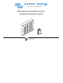
victron energy
B L U E
P O W E R
Bus-based power distribution system
Installation & Operation manual
VE.NET DC
victron energy
B L U E
P O W E R
Copyrights © 2006 Victron Energy B.V.
All Rights Reserved
This publication or parts thereof, may not be reproduced in any form, by any method,
for anypurpose.
For conditions of use and permission to use this manual for publication in other than
the English language, contact Victron Energy B.V.
VICTRON ENERGY B.V. MAKES NO WARRANTY, EITHER EXPESSED OR
IMPLIED, INCLUDING BUT NOT LIMITED TO ANY IMPLIED WARRANTIES OF
MERCHANTABILITY OR FITNESS FOR A PARTICULAR PURPOSE, REGARDING
THESE VICTRON ENERGY PRODUCTS AND MAKES SUCH VICTRON ENERGY
PRODUCTS AVAILABLE SOLELY ON AN “AS IS” BASIS.
IN NO EVENT SHALL VICTRON ENERGY B.V. BE LIABLE TO ANYONE FOR
SPECIAL, COLLATERAL, INCIDENTAL, OR CONSEQUENTIAL DAMAGES IN
CONNECTION WITH OR ARISING OUT OF PURCHASE OR USE OF THESE
VICTRON ENERGY PRODUCTS. THE SOLE AND EXCLUSIVE LIABILITY TO
VICTRON ENERGY B.V., REGARDLESS OF THE FORM OF ACTION, SHALL NOT
EXCEED THE PURCHASE PRICE OF THE VICTRON ENERGY PRODUCTS
DESCRIBED HERE IN.
Victron Energy B.V. reserves the right to revise and improve its products as it sees fit.
This publication describes the state of this product at the time of its publication and
may not reflect the product at all times in the future.
2
Installation & operation manual
victron energy
Installation & operation manual
B L U E
P O W E R
Table of contents
1
2
Introduction .............................................. 4
1.1 General
4
VE.Net DC......................................... 4
Features ............................................ 4
About this manual.............................. 4
1.2 Safety
4
General.............................................. 4
Modifications ..................................... 4
Service and technical support ........... 4
1.3 Overview 5
Overview of components................... 5
Installation................................................ 6
2.1 Install the system............................... 6
Precautions ....................................... 6
Calculate the needed power.............. 7
Select the nodes................................ 8
Routing from the appliance(s) to the
node .................................................. 9
Routing of the bus cable and main
fuse box........................................... 10
Install the main fuse box.................. 11
Connect to the battery ..................... 12
Connect the direct power nodes
(DPN) .............................................. 13
Install the switch panel .................... 14
Install the node ................................ 16
2.2 Configure the system.......................19
Priority .............................................19
Switch mode ....................................19
Navigation lights ..............................19
Bilge-pump ......................................19
Feedback defective lamp/cable .......19
Reconfigure .....................................19
Store the configuration ....................19
2.3 Start the system the first time ..........20
Configure one switch to one node ...21
Configure one switch to more than
one node..........................................21
Configure more than one switch to
one node..........................................22
Change priority ................................22
Change feedback of defective
lamp/wire .........................................23
Delete connection between switch
and node..........................................24
3
4
5
Operation .............................................. 25
Push button panel overview............ 25
Switch on the system ...................... 26
Background light ............................. 26
Warning lights ................................. 27
Indications of the appliances .......... 27
Detection of doors and hatches ...... 28
Direct Power Node (DPN)............... 29
Switch off the system ...................... 30
Maintenance.......................................... 31
4.1 Troubleshooting .............................. 31
4.2 Replace the node............................ 32
If no new nodes are available: ........ 32
4.3 Technical specifications .................. 33
4.4 Spare parts 34
Appendix ............................................... 36
Configuration table (3x)................... 36
3
victron energy
B L U E
Installation & operation manual
P O W E R
1 Introduction
1.1
General
VE.Net DC
Features
About this manual
Congratulations on purchasing a VE.Net
DC bus power distribution system for
your vessel. The system is delivered as
a set and can be assembled according
to CE standard. It is essential therefore
to follow the installation instructions
carefully.
VE.Net DC is a modern electronically
controlled bus system. Special built in
features reduce the risk of a cable fire or
a low-voltage situation.
Built in features include:
• An electronic fuse for each load. The
fuse can be reset with the switch
push button.
• All warnings are both visual and
audible.
• A warning for broken (navigation)
light or wire.
• A warning for overloads. The
appliance turns off automatically.
• A warning for low voltage. The
appliance turns off automatically.
• An adjustable background light in the
switch panel.
This user manual describes the
installation and operation of the VE.Net
DC system. Read this manual carefully
before use or operation of the product. In
case you have any doubt about a
procedure contact your dealer.
1.2
Safety
General
Modifications
Observe all safety instructions. Use this
product only for the purpose it is
intended for. Please contact your dealer
immediately if a potential danger arises
during the use of this product.
Modifications to the product are not
permitted.
Service and technical support
For information concerning specific
settings, maintenance or repair work,
contact your local dealer.
4
victron energy
Installation & operation manual
1.3
B L U E
P O W E R
Overview
Overview of components
A. Cable harness including:
• 10 A fuse
• 50 A fuse
• 10 A. direct power node
• 20 A. direct power node
• 2 × 15 m. bus cable
• 8 m cable for push button panel
• 8 m cable for bilge-pump
• 8 m cable for instruments
B. Push button panel
C. 3 A. power nodes
D. 10 A. power nodes
E. 16 A. power nodes
F. Sensor node for bilge-pump
G. Cable cutter
H. DC 4 compound (tube)
I. CD labels
C(5x)
3
D(8x)
10
F(1x)
S
A(1x)
G(1x)
H(1x)
B(1x)
E(2x)
16
I(1x)
5
victron energy
B L U E
Installation & operation manual
P O W E R
2 Installation
2.1
Install the system
Precautions
Observe the following when you wire the
system:
1. Never install any components above
batteries or fuel tanks.
2. Never install components or cables
near heat sources that may melt the
insulation.
3. Never expose components or
cables to oil or grease.
4. Never install components when
there is a risk of exposure to water.
5. Never use twist-on connectors.
6
•
•
•
•
•
Always use insulation barriers to
prevent a short circuit of exposed
terminal connectors.
Always use the correct tool.
Always take the necessary
precautions to protect the
components and cables from
damage.
Always clamp the wires at least
every 30 cm (12”).
Protect cables that pass bulkheads
or structural members against
damage by grummets or equivalent
means.
•
•
•
•
•
Protect components and wires with
sheets, conduits or equivalent means
when there is a risk of physical
damage.
All wires must be fire resistant, finestranded and tinned.
Always use the correct cable
diameter and colour. This is indicated
on the node.
Wires outside the motor
compartment must be rated at
minimum 60 °C / 140 °F.
Wires inside the motor compartment
must be rated at minimum 70 °C /
158 °F.
Installation & operation manual
victron energy
B L U E
P O W E R
Calculate the needed power
Calculate the total power and the
amount of nodes for each bus-cable
before you start installation.
1. Calculate for each single appliance
or groups of appliances the power
needed.
• 1 A per 10 W for a 12 V system
• 0,5 A per 10 W for a 24 V system
2. Divide the appliances as evenly as
possible between the two bus cables.
Each bus cable can have a
maximum load of 50 A.
3. Select the node with the correct
amperage. Refer to Select the
nodes.
4. Write down the configuration of the
nodes in the Configuration tables.
Refer to the Error! Not a valid
bookmark self-reference..
Warning!
Do not install nodes in a
petrol engine compartment or
a gas locker. There is a risk
of ignition and explosion.
Note: Appliances connected to the
Direct Power Nodes do not influence the
total power on a bus cable.
7
victron energy
B L U E
Installation & operation manual
P O W E R
Select the nodes
We recommend the following set-up:
Node
Appliance
Cable Diameter
2
(mm )
(AWG)
3A
Navigation light
Interior light
Deck light
Instruments
Interior light
Power outlet
Refrigerator
Fresh water pump
Bilge-pump
Automatic switch bilge-pump
1,5
16
1,5
16
2,5
14
1,5
16
10 A
16 A
Sensor node on/off
Note: Connect the delivered sensor
node to the automatic switch of the bilgepump.
8
Caution!
The node triggers when there
is more power applied than
specified.
Caution!
Connect the radar, compass
GPS and bilge-pump to a
direct power node. The direct
power nodes are located in
the main fuse box.
victron energy
Installation & operation manual
B L U E
P O W E R
Routing from the appliance(s) to the node
Node
1. Lay-out the wires from the appliance
to where the node will be placed.
2. Cut the wires to the correct length.
Allow extra length to tighten up the
cables with tie-wraps. Refer to the
drawing.
3. Attach the connectors on the end of
the wires.
4. Lay-out single appliances directly to
the node.
Node
5. Lay-out group appliances parallel to
the node.
9
victron energy
B L U E
Installation & operation manual
P O W E R
Routing of the bus cable and main fuse box
max. 200 cm
80"
1. Lay-out the bus-, instrument-,
switchboard- and bilge-pump cables
and the main fuse box to where they
will be placed.
Note: Make sure the main fuse box
is easy to access.
10
Warning!
Do not install nodes in a
petrol engine compartment or
a gas locker. There is a risk of
ignition and explosion.
Note: Make sure that the cable between
the fuse box and the battery has a
maximum length of 200 cm (80”).
Warning!
If the +cable (red) between
the main fuse box and the
battery is longer than 200 cm
(80”), it needs a fuse of 80 A
at the battery.
victron energy
Installation & operation manual
B L U E
P O W E R
Install the main fuse box
1. Remove the cover of the main fuse
box.
Note: Make sure the main fuse box
is easy to access.
2. Install the main fuse box on a
suitable surface.
3. Set the fuses in the OFF position.
4. Replace the front cover.
Warning!
Make sure all fuses are set in
the OFF position.
11
victron energy
B L U E
Installation & operation manual
P O W E R
Connect to the battery
20 mm
6/8"
15 mm
5/8"
1. If necessary, adjust the length of the
bus wires at the main fuse box.
2. Remove the cover of the main fuse
box.
3. Loosen the screw to remove the wire
on the fuse.
4. Cut the wire.
5. Remove 15 mm (5/8“) of the
insulation at the end of the wire. Use
the cable cutter to cut the insulation.
6. Place the wire back on its place.
7. Tighten the screw to secure the wire.
Note: Do the procedure for one wire
at a time.
Warning!
Follow the instructions
properly to reduce the risk of
future shortcut with possible
fire.
12
8. Clamp the bundles of + (red) and –
(black) battery wires with at least
20 mm (6/8") distance in between.
9. Connect the red cable to the +
terminal on the battery.
10. Connect the black cable to the terminal on the battery.
Warning!
Make sure there is no risk of
physical damage for the
cables. In case there is a risk,
protect the cables with
grummets or equivalent.
victron energy
Installation & operation manual
B L U E
P O W E R
Connect the direct power nodes (DPN)
12
11
12
11
30 cm
12"
Fusebox
Max 10 A
DPN
1. Start from the main fuse box.
2. Clamp the 10 A Direct Power Node
(DPN) wires to the instruments.
If necessary, install a multiple fuse
box with a total of 10 A between the
different instruments and the node.
Refer to the illustration.
3. Clamp the 20 A DPN wires to the
bilge-pump.
Note: Do not connect the wires to the
appliances mentioned.
4. Attach the wires for the push button
panel. Leave 30 – 40 cm (12 – 16“)
extra length for easy connection of
the switch panel.
5. Attach the wires with a clamp every
30 cm (12“).
Note: Clamp the wires of the
instruments, bilge-pump and switch
board separated from the bus cable.
Caution!
The instruments and VHF
may need a separate fuse.
Refer to the instrument user
manual.
13
victron energy
B L U E
Installation & operation manual
P O W E R
Install the switch panel
O
20 mm
6/8"
1. Remove the cover of the switch
panel.
Note:
• Handle the cover with the
electronics with care.
• Do not touch the electronics.
• Place the cover with the
electronics in the box during
installation.
14
2. Feed the wires through a 20 mm
(6/8“) hole.
3. Feed the wires through the back
panel.
3. Install the back panel on a suitable
surface.
victron energy
Installation & operation manual
B L U E
P O W E R
Bus
GND
VBAT
Violet
Black
Red
4. Insert the labels in the cover.
Note:
• Switch 1 and 4 are reserved for
the bilge-pump.
• If necessary, make new labels
with the delivered CD.
• Use an overhead sheet to print
the labels.
5. Connect the wires to the electronics.
6. Replace the front cover.
15
victron energy
B L U E
Installation & operation manual
P O W E R
Install the node
2 mm
1/16"
Note: Start with the node closed to
the main fuse box.
1. Install the node base onto a suitable
surface.
Note:
• Align the side of the node marked
with + with the red bus cable
• Align the side of the node marked
with – with the black bus cable.
16
2. Push the wires into the base.
3. Mark the places of the clips on the
wires.
Warning!
Do not use the node base and
the clips more than one time.
Mounting deforms the clips
and base.
4. Cut the insulation with the cable
cutter.
5. Bend the wire several times until
2 mm (1/10”) of the conductors are
exposed.
victron energy
Installation & operation manual
6. Push the clips onto the wire. Make
sure the clips make contact with the
exposed wires.
7. Put some DC4 compound around the
clips.
B L U E
8. Push the clips into place to secure.
9. Repeat these steps for the other
wire.
P O W E R
10. Put some DC4 compound around the
violet wire. Put the compound on the
place of the single clip.
11. Push the wire into its position.
12. Use a hammer to secure the clip in
the base.
17
victron energy
B L U E
Installation & operation manual
P O W E R
30 cm
12"
13. Place the middle cover
14. Attach the proper node.
15. Attach the connectors to the wires
and clamp them accordingly.
Caution!
Do not connect the wires to
the node. This will be done
during the configuration of
the system.
18
16. Attach the wires with a clamp every
30 cm (12”). Allow some space for
additional nodes to install.
17. On the end of the bus cable:
Cut the bus cables to the proper
length and insulate them with
insulating tape.
victron energy
Installation & operation manual
2.2
B L U E
P O W E R
Configure the system
Priority
Switch mode
Navigation lights
The node priority is used when there is
an overload or low voltage situation. The
nodes with a low priority turn off first to
make sure important systems remain in
operation. Therefore it is important to set
the priority of each node correctly.
The priority is automatically set in the
order of configuring the nodes. The first
configured nodes are set to the highest
priority.
The switch buttons can be set to two
different switch modes:
•
Toggle mode:
When the switch is pushed, the
appliance functions until the switch is
pushed again. Use this mode for the
refrigerator, lights etc.
•
Direct mode:
The appliance functions as long as
the switch is pushed. Use this mode
for the horn, winch etc.
There are three options:
1. Configure each lamp to a separate
node, but to the same switch. The
switch indicates malfunction, but not
which light is defective.
2. Configure each lamp to a separate
switch and a separate node. The
indication shows which light is
defective.
3. Configure each lamp to a separate
node, but to the same switch.
Combined with a VE.Net DC
Navigation light board it is easy to
see which light is defective.
Bilge-pump
Feedback defective lamp/cable
Reconfigure
The bilge-pump and its sensor node do
not need to be configured. They are set
in the factory on switch 1 (automatic)
and switch 4 (manual) with the highest
priority. It is enough to connect the Direct
Power Node (DPN) wires to the pump
and the automatic switch to the sensor
node.
The system indicates whether a
lamp/wire is defective or when a motor is
not running. It is possible to configure
the appliance not to include this
indication. This is recommended for
appliances such as 12 V outlet,
refrigerator, automatic pumps etc.
1. Disconnect the appliance from the
node.
2. Follow the procedure as for normal
configuration.
Caution!
The reconfigured appliance is
set to the lowest priority.
Store the configuration
It is necessary to store each
configuration separately. To do this, turn
the push button panel off and on after
you finished the specific configuration.
19
victron energy
B L U E
2.3
Installation & operation manual
P O W E R
Start the system the first time
1. Switch on all main fuses.
2. Switch on the push button panel.
Warning:
In case of immediate alarm
(buzzer and lightening of the
polarity warning led):
1. Turn of the system through
the main fuses immediately.
2. Check the polarity at the
batteries. Change if necessary.
3. Turn on the system again.
See chapter Maintenance.
20
3. Proceed with configuration.
victron energy
Installation & operation manual
B L U E
P O W E R
Configure one switch to one node
Toggle
C2
2 sec
C1
Direct
5 sec
1. Push the + and – for two seconds.
The display shows C1.
2. Connect the appliance to the node.
The display shows C2. The buzzer
gives a signal.
C3
3. Push the desired push button.
• Push shortly to select toggle
mode. The display turns off and
the buzzer stops.
• Push for 5 seconds to select
direct mode. The display shows
C3 and the buzzer stops.
Configure one switch to more than one node
Use the above procedure. Repeat the
procedure for each node that you want
to connect to the switch.
21
victron energy
B L U E
Installation & operation manual
P O W E R
Configure more than one switch to one node
2 sec
C1
1. Do the procedure as in ´Configure
one switch to one node´.
2. Push the + and – for two seconds.
The display shows C1.
1
C4
3. Push the first configured switch
button shortly.
#
4. Push the desired switch shortly. The
switch is configured automatically to
the same mode as the first switch.
The display turns off.
Change priority
P0
2 sec
C1
1. Push the + and – for two seconds.
The display shows C1.
22
x2
P1
2. Push the + 2 times shortly.
The display shows P0.
3. Push the – to set the priority.
The display shows P1, P2 or P3.
P1 is high priority.
#
4. Push the switch button that
corresponds to the node.
The display turns off.
Caution!
Do not set all appliances to
the same priority.
victron energy
Installation & operation manual
B L U E
P O W E R
Change feedback of defective lamp/wire
Fb
2 sec
C1
1. Push the + and – for two seconds.
The display shows C1.
3x
F1
F0
2. Push the + 3 times shortly.
The display shows Fb (Feedback).
3. Push the – to set the feedback:
• F1: Feedback on;
• F0: Feedback off (recommended
for refrigerator, automatic running
motor, and groups of separately
switched appliances.
#
4. Push the switch button that
corresponds with the node.
The display turns off.
Note:
Be aware that an automatic motor and
appliances with separate conventional
switches, when not activated, will
indicate “defective lamp/wire”.
23
victron energy
B L U E
Installation & operation manual
P O W E R
Delete connection between switch and node
rS
2 sec
C1
4x
#
1. Push the + and – for two seconds.
The display shows C1.
24
2. Push the + 4 times shortly.
The display shows rS (Reset).
3. Push switch to delete shortly:
The switch illuminates green and the
appliance switches on.
4. Turn off and on the push button
panel to store the deleted function.
The green light and the appliance
turn off. The connection between the
switch and the node is deleted.
victron energy
Installation & operation manual
B L U E
P O W E R
3 Operation
Push button panel overview
A.
B.
C.
D.
E.
F.
G.
On/off
Push button
Label
Warning light ´Over current´
Warning light ´Polarity´
Display
- Button (background light /
configuration)
H. + Button (background light /
configuration)
C
D
over current
E
G
polarity
C3
A
B
F
H
1
2
3
4
5
6
7
8
9
10
11
12
13
14
15
16
17
18
19
20
21
25
victron energy
B L U E
Installation & operation manual
P O W E R
Switch on the system
#
1. Switch on all fuses.
2. Push the ON/OFF button.
The indication lights in the ON/OFF
switch and the + and – buttons turn
on (green). The switch panel is ready
for use.
3. Push the switch button of the node to
turn on the corresponding appliance.
A green light in the switch button
indicates that the corresponding
node is turned on.
1. Push + to increase the level of the
background light.
The maximum level is 6. A beep
signals that this level is reached.
2. Push – to decrease the level of the
background light.
The minimum level is 1. A beep
signals that this level is reached.
Background light
When the switch panel is turned on, the
background light is illuminated in the
medium level (level 4).
26
victron energy
Installation & operation manual
B L U E
P O W E R
Warning lights
The two warning light on the push-button
panel warn you for the following failures:
•
Wrong polarity
•
Overload of the system / low voltage
Light
Polarity
Buzzer
Continuous
Meaning
Battery connected wrong, the
+ and – connectors have
been mismatched
Overload
Interrupted
The system is overloaded or
the battery voltage is too low
(battery is discharged).
Light
Green
Buzzer
No
Blinking
green
Yes
Blinking
green / red
Blinking red
Yes
Meaning
Appliance is turned on and
functions normally.
No appliance. Light defective
or wire between node and
appliance defective.
Circuit is nearly overloaded or
node is nearly overheated.
Circuit is overloaded or
overheated and turned off
automatically
Action
Turn off all fuses in the fuse
box.
Check the polarity of battery
and change it correctly.
Devices may be overheated
and damaged if the polarity
was wrong for over a minute.
Turn off appliances that are
not absolutely necessary. If
the situation continues, the
system switches off
appliances automatically in
order of priority.
Indications of the appliances
Each appliance is automatically tested
during its operation. In that case, the
light in the switch button is green.
Other indications in the push-buttons are
explained in the table.
In case of a failure, turn off the appliance
with the push-button. The buzzer,
indication led and automatic fuse are
reset. Repair the appliance. Switch on
the appliance to test.
Yes
Action
Check lights or wires.
Press the – button to reset
the buzzer.
Turn off the node.
Push the switch button to
reset. Check the wires from
the node to the appliance for
short circuits.
27
victron energy
B L U E
Installation & operation manual
P O W E R
Detection of doors and hatches
The buttons on the switch panel can be
used for detection if a door or a hatch is
opened. For this purpose, a special
sensor node is necessary.
28
Light
Meaning
Red
Door / hatch / switch closed
Door / hatch / switch open
victron energy
Installation & operation manual
B L U E
P O W E R
Direct Power Node (DPN)
l
ita
Dig er
w
po
on
t
ec
Dir er
w
po
on
r
we
po f
of
Appliances that are connected to a direct
power node are normally switched on by
the switch board.
l
ita
Dig er
w
po
on
t
ec
Dir er
w
po
on
r
we
po f
of
In case of malfunction of the switch
board:
1. Push the bypass fuse on the direct
power node to switch on the
appliance.
l
ita
Dig er
w
po
on
t
ec
Dir er
w
po
on
r
we
po f
of
In case the appliance cannot be turned
off with the switch board:
2. Release the power fuse of the direct
power node.
29
victron energy
B L U E
Installation & operation manual
P O W E R
Switch off the system
over current
1
polarity
2
1. Push the ON/OFF switch.
The indication lights and appliances
turn off.
Note: In case the bilge-pump operates
while you turn off the system, it stays in
operation.
30
Warning!
Always Turn off all fuses in
the main fuse box before you
start working on the electrical
system!
Note: In case it is preferred to leave
some appliances (e.g. refrigerator, alarm
installation) in operation, it is necessary
to leave the system on. To minimize the
power consumption of the system,
decrease the background light. Refer to
Background light
victron energy
Installation & operation manual
B L U E
P O W E R
4 Maintenance
4.1
Troubleshooting
Problem
Polarity light is illuminated, a continuous
beep is heard.
Possible cause
•
Battery is connected wrong.
No action when the ON/OFF button is
pushed.
•
•
After a button is pushed, no warnings and
no power at the appliance.
•
•
Overload light is illuminated, a interrupted
beep is heard.
•
•
Switch blinks red, a beep is heard.
•
Switch blinks green, a beep is heard.
•
•
Bilge-pump or instruments connected via
a direct power node cannot be turned off.
•
•
The 10 A fuse in the main fuse box is
released.
Push button panel is connected
wrong.
The 50 A fuse in the main fuse box is
released.
Bus cable and node are connected
wrong.
The voltage is low.
The circuit is overloaded.
Short circuit between node and
appliance.
Wire between node and appliance is
defective.
Light is defective.
The bypass fuse of the direct power
node is switched on.
DPN is defective.
Possible solution
•
Turn off the main power immediately.
•
Check the polarity of the battery
connection.
•
Check the voilet bus wire.
•
Reset the fuse
•
Check the connections of the switch
panel. Reconnect if necessary.
•
Check the red plus wire.
•
Reset the fuse.
•
Check the connections between bus
cable an the node. Reconnect if
necessary.
•
Turn off appliances. If not, the system
turns off appliances automatically by
order of priority.
•
Check the wires between the
appliance and node.
•
In case of a built-in safety device in
the appliance: turn off the warning.
Refer to Feedback defective
lamp/cable.
•
Replace the lamp of the light.
•
Turn off the bypass fuse of the DPN.
•
Turn off the power of the DPN.
31
victron energy
B L U E
4.2
Installation & operation manual
P O W E R
Replace the node
Red/Violet
1. Switch off all fuses.
2. Unplug the connectors on the node.
Make sure which connector is
connected to + and –.
3. Push a screwdriver into the node for
approximately 5 mm.
4. Turn the screwdriver; you may need
to apply some force because of
possible corrosion.
5. Push in the new node.
Note: Make sure to replace the node
with a new one of the same type.
6. Configure the node. Refer to
Configure the system.
32
If no new nodes are available:
Warning!
Use this procedure only in
case of an emergency and
when no spare parts are
available.
Warning!
Make sure the + and – cables
cannot make contact with
each other. Possible risk of
short circuit!
Black
For appliances connected via a power
node:
1. Disconnect the node. Follow steps 1
to 4 of the procedure on the left.
2. Place a wire between the black cable
of the bus and the black cable of the
appliance.
3. Take a fuse with the same rating as
the corresponding node.
4. Place the fuse with a wire between
the red cable of the bus and the red
cable of the appliance.
victron energy
Installation & operation manual
4.3
B L U E
P O W E R
Technical specifications
System voltage
Voltage range
Standby power consumption
Active power consumption
Storage temperature
Operational temperature
Maximum bus cable length
Maximum number of nodes
Maximum length of bus cables (for boats)
Maximum load with 15 m of bus cable
Maximum number of bus cables
Weight of a 130 A system with 20 nodes
Complies to
International standards
CE approval
EMC approvals
:
:
:
:
:
:
:
:
:
:
:
:
:
:
:
:
12 V
10-16 V
<10 mA
Approximately 100 mA
-20 ºC to +70 ºC (-4 °F to 158 °F)
-4 ºC to +50 ºC (24 °F to 122 °F)
100 m / 328 ft
255
15 m / 50 ft
50 A
Indefinite
20 kg / 44 lbs
94/25/EC and 89/336/EEC
ISO 10133
Yes
EN 61000-6-2 (2001) and EN 61000-6-3
(2001)
33
victron energy
B L U E
4.4
Installation & operation manual
P O W E R
Spare parts
8
5
7
6
9
15m
2
1
3
10
34
4
11
12
13-14-15-16-17-18-19
20
victron energy
Installation & operation manual
Number
1
2
3
4
5
6
7
8
9
10
11
12
13
14
15
16
17
18
19
20
Article description
Main Fuse 10 A
Direct power node 10 A
Fuse 10 A
Main Fuse 50 A
Direct power node 20 A
Fuse 20 A
Cabling bus 50 A (complete)
Cable cutter
Dielectric gel
Frame 21 keys / Navigation light
Push-button plate
Node base single
Power node 16 A
Power node 10 A
Power node 3 A
Branch node
Sensor node switch 12 V
Sensor node open/close 12 V
Sensor node level 12 V
Slides node base single
B L U E
P O W E R
Article number
MF10A-0
DPN10A-0
DPNF 10A-0
MF50A-0
DPN20A-0
DPNF20A-0
CB50A-0
CC16-0
DC4-0
FPB21NL-0
PBP21K12V-0
NB1-0
PN16A-0
PN10A-0
PN3A-0
BN-0
SNS12V-0
SNOC12V-0
SNL12V-0
SNB1-0
35
victron energy
B L U E
P O W E R
5 Appendix
The following sections can be used and (when necessary) removed from this manual:
Configuration table (3x)
36
Installation & operation manual
victron energy
Installation & operation manual
B L U E
Configuration table
Type node
Serial
nr.
P O W E R
Bus cable number: . . . . . . . . . . . . . . . . .
Priority
Switch
nr.
Type of appliance
Amperage
Total amperage for the bus cable
37
victron energy
B L U E
Installation & operation manual
P O W E R
Configuration table
Type node
Serial
nr.
Bus cable number: . . . . . . . . . . . . . . . . .
Priority
Switch
nr.
Type of appliance
Total amperage for the bus cable
38
Amperage
victron energy
Installation & operation manual
B L U E
Configuration table
Type node
Serial
nr.
P O W E R
Bus cable number: . . . . . . . . . . . . . . . . .
Priority
Switch
nr.
Type of appliance
Amperage
Total amperage for the bus cable
39
victron energy
B L U E
P O W E R
Victron Energy B.V.
De Paal 35
1351 JG ALMERE
The Netherlands
www.victronenergy.com
[email protected]