1
Drive Technology \ Drive Automation \ System Integration \ Services
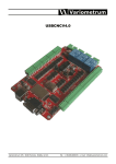
MOVI-PLC® advanced DHR41B Controller
EtherNet/IP, Modbus/TCP and
PROFINET IO Fieldbus Interfaces
Edition 03/2009
16730410 / EN
Manual
SEW-EURODRIVE – Driving the world
1 General Notes ......................................................................................................... 6
1.1 How to use this documentation ...................................................................... 6
1.2 Structure of the safety notes .......................................................................... 6
1.3 Rights to claim under limited warranty ........................................................... 7
1.4 Exclusion of liability ........................................................................................ 7
1.5 Copyright........................................................................................................ 7
2 Safety Notes ........................................................................................................... 8
2.1 Other applicable documentation .................................................................... 8
2.2 Bus systems................................................................................................... 8
2.3 Safety functions ............................................................................................. 8
2.4 Hoist applications ........................................................................................... 8
2.5 Product names and trademarks ..................................................................... 8
2.6 Disposal ......................................................................................................... 8
3 Preface .................................................................................................................... 9
3.1 Content of this manual ................................................................................... 9
3.2 Characteristics ............................................................................................... 9
3.2.1 Process data exchange ...................................................................... 9
3.2.2 Parameter access ............................................................................... 9
3.2.3 Monitoring functions .......................................................................... 10
4 Assembly and Installation Notes for Ethernet................................................... 11
4.1 Connecting MOVI-PLC® advanced DHR41B to an Ethernet network ......... 11
4.2 Pin assignment of X30-1 and X30-2 ............................................................ 11
4.3 Shielding and routing bus cables ................................................................. 12
4.4 The integrated Ethernet switch .................................................................... 13
4.5 Setting the DIP switches .............................................................................. 14
4.6 Status LED of the DHR41B option ............................................................... 15
4.6.1 Status LEDs in EtherNet/IP and Modbus/TCP operation .................. 15
4.6.2 Status LEDs in PROFINET operation ............................................... 16
4.6.3 Link/Activity LEDs ............................................................................. 17
4.7 TCP/IP addressing and subnetworks........................................................... 18
4.8 Setting the IP address parameters............................................................... 20
4.9 Procedure for unit replacement.................................................................... 22
5 Configuration and Startup (EtherNet/IP) ............................................................ 23
5.1 Validity of the EDS file for DHR41B ............................................................. 23
5.2 Configuring the master (EtherNet/IP scanner) ............................................. 24
5.3 Settings in MOVI-PLC® advanced DHR41B ................................................ 27
5.3.1 Process data configuration ............................................................... 27
5.3.2 Status of the fieldbus interface ......................................................... 27
5.4 Configuration examples in RSLogix 5000 .................................................... 28
5.4.1 MOVI-PLC® advanced DHR41B with 16 PD data exchange ............ 28
5.4.2 Access to the parameters of MOVI-PLC® advanced DHR41B ......... 31
5.4.3 Access to unit parameters of downstream units ............................... 36
6 The Ethernet Industrial Protocol (EtherNet/IP) ................................................ 37
6.1 Introduction .................................................................................................. 37
6.2 Process data exchange ............................................................................... 37
6.3 CIP object directory...................................................................................... 38
6.4 Return codes for parameter setting via explicit messages........................... 51
Manual – MOVI-PLC® advanced DHR41B for EtherNet/IP, Modbus/TCP and PROFINET IO
3
7 Configuration and Startup (Modbus/TCP) ......................................................... 55
7.1 Unit description file for Modbus/TCP............................................................ 55
7.2 Configuration of the master (Modbus scanner)............................................ 55
7.3 Settings in MOVI-PLC® advanced DHR41B ................................................ 58
7.3.1 Process data configuration ............................................................... 58
7.3.2 Status of the fieldbus interface ......................................................... 58
7.4 Configuration examples in PL7 PRO ........................................................... 59
7.4.1 MOVI-PLC® advanced DHR41B with 16 PD data exchange ............ 59
7.5 Examples for data exchange via Modbus/TCP ............................................ 61
7.5.1 Writing and reading process data ..................................................... 62
7.5.2 Parameter access ............................................................................. 64
8 The Modbus Protocol (Modbus/TCP) ................................................................. 66
8.1 Introduction .................................................................................................. 66
8.1.1 Mapping and addressing .................................................................. 66
8.1.2 Services (function codes) .................................................................. 67
8.1.3 Access .............................................................................................. 67
8.2 Protocol structure ......................................................................................... 68
8.2.1 Header .............................................................................................. 68
8.2.2 Service FC3 Read holding registers ................................................ 69
8.2.3 Service FC16 Write multiple registers .............................................. 70
8.2.4 Service FC23 Read/write multiple registers ..................................... 71
8.2.5 Service FC43 Read device identification ......................................... 72
8.3 Connection management ............................................................................. 73
8.3.1 Sending process output data (requesting a controlling connection) . 73
8.3.2 Dropping connections ....................................................................... 74
8.3.3 Timeout monitoring ........................................................................... 74
8.4 Parameter access via Modbus/TCP............................................................. 75
8.4.1 Procedure with FC16 and FC3 ......................................................... 75
8.4.2 Procedure with FC23 ........................................................................ 75
8.4.3 Protocol structure .............................................................................. 76
8.4.4 MOVILINK® parameter channel ........................................................ 77
8.5 Fault codes (exception codes) ..................................................................... 78
9 Fault Diagnostics for Operation on EtherNet/IP and Modbus/TCP ................. 79
9.1 Diagnostic sequence.................................................................................... 79
10 PROFINET IO Configuration................................................................................ 81
10.1 Configuring the PROFINET IO controller ..................................................... 81
10.1.1 Installing the GSD file ...................................................................... 81
10.1.2 Assigning a PROFINET device name .............................................. 82
10.2 Configuring the PROFINET connection for MOVI-PLC®
advanced DHR41B ...................................................................................... 84
10.2.1 Creating a new project ..................................................................... 84
10.2.2 Configuring a station ........................................................................ 86
10.3 PROFINET configuration with topology detection........................................ 88
10.3.1 Introduction ...................................................................................... 88
10.3.2 Configuring the PROFINET topology ............................................... 89
10.3.3 Changing the port properties ........................................................... 91
10.3.4 Topology diagnostics ....................................................................... 93
10.3.5 Port statistics .................................................................................... 94
10.4 PROFINET diagnostics alarms .................................................................... 96
10.4.1 Switching on the diagnostic alarms .................................................. 96
10.4.2 Determining the cause of a fault ...................................................... 97
4
Manual – MOVI-PLC® advanced DHR41B for EtherNet/IP, Modbus/TCP and PROFINET IO
11 Operating Behavior (PROFINET IO).................................................................... 98
11.1 Process data exchange with MOVI-PLC® advanced DHR41B.................... 98
11.2 Settings in MOVI-PLC® advanced DHR41B .............................................. 100
11.2.1 Status of the PROFINET fieldbus interface .................................... 100
11.3 Parameterization via PROFIdrive data record 47 ...................................... 102
11.3.1 Introduction to PROFINET data records ........................................ 102
11.3.2 Structure of the PROFINET parameter channel ............................ 105
11.3.3 Parameter setting procedure via data record 47 ............................ 106
11.3.4 Controller processing sequence ..................................................... 107
11.3.5 Addressing downstream inverters .................................................. 108
11.3.6 MOVILINK® parameter requests .................................................... 109
11.3.7 PROFIdrive parameter requests .................................................... 114
12 Error Diagnostics on PROFINET....................................................................... 119
12.1 Diagnostic procedure ................................................................................. 119
12.1.1 Diagnostics problem 1: MOVI-PLC®
advanced DHR41B not working on PROFINET IO ......................... 120
12.1.2 Diagnostics problem 2: No process data exchange
with the I/O controller ...................................................................... 121
13 Appendix ............................................................................................................. 122
13.1 Parameter access via EtherNet/IP to downstream units............................ 122
13.2 Parameter access via Modbus/TCP or PROFINET to downstream units .. 123
13.3 Parameter access via engineering interface to downstream units............. 124
13.4 Glossary ..................................................................................................... 125
14 Index .................................................................................................................... 126
Manual – MOVI-PLC® advanced DHR41B for EtherNet/IP, Modbus/TCP and PROFINET IO
5
General Notes
How to use this documentation
1
1
General Notes
1.1
How to use this documentation
MOVI-PLC¬???/IP, Modbus/TCP und PROFINET IO
The documentation is an integral part of the product and contain important information
on operation and service. The documentation is written for all employees who assemble,
install, startup, and service this product.
1.2
Structure of the safety notes
The safety notes in this documentation are designed as follows:
Pictogram
SIGNAL WORD
Type and source of danger.
Possible consequence(s) if disregarded.
•
Pictogram
Example:
Measure(s) to prevent the danger.
Signal word
Meaning
Consequences if
disregarded
DANGER
Imminent danger
Severe or fatal injuries
WARNING
Possible dangerous situation
Severe or fatal injuries
CAUTION
Possible dangerous situation
Minor injuries
NOTICE
Possible damage to property
Damage to the drive system or its environment
TIP
Useful information or tip.
Simplifies the handling of the
drive system.
General danger
Specific danger,
e.g. electric shock
6
Manual – MOVI-PLC® advanced DHR41B for EtherNet/IP, Modbus/TCP and PROFINET IO
General Notes
Rights to claim under limited warranty
1.3
1
Rights to claim under limited warranty
A requirement of fault-free operation and fulfillment of any rights to claim under limited
warranty is that you adhere to the information in the documentation. Read the documentation before you start working with the unit!
Make sure that the documentation is available to persons responsible for the system and
its operation as well as to persons who work independently on the unit. You must also
ensure that the documentation is legible.
1.4
Exclusion of liability
You must observe this publication and the documentation of the connected units from
SEW-EURODRIVE to ensure safe operation and to achieve the specified product characteristics and performance requirements. SEW-EURODRIVE assumes no liability for
injury to persons or damage to equipment or property resulting from non-observance of
the operating instructions. In such cases, any liability for defects is excluded.
1.5
Copyright
© 2008 - SEW-EURODRIVE. All rights reserved.
Copyright law prohibits the unauthorized duplication, modification, distribution, and use
of this document, in whole or in part.
Manual – MOVI-PLC® advanced DHR41B for EtherNet/IP, Modbus/TCP and PROFINET IO
7
Safety Notes
Other applicable documentation
2
2
Safety Notes
2.1
Other applicable documentation
Note also the following documentation:
•
'MOVI-PLC ® advanced DHE41B/DHF41B/DHR41B Controller' manual
•
'MOVI-PLC® Programming in the PLC Editor' manual
The following publications and documents apply to the connected units:
•
Operating instructions of the units
(Units are, for example, MOVIDRIVE® B, MOVITRAC® B, MOVIAXIS®)
•
For units with functional safety technology, also the respective
'Safe Disconnection - Conditions' manuals
2.2
Bus systems
MOVI-PLC® advanced DHR41B supports various bus systems. A bus system makes it
is possible to adapt frequency inverters to the particulars of the machinery within wide
limits. As with all bus systems, there is a danger of invisible, external (as far as the inverter is concerned) modifications to the parameters which give rise to changes in the
unit behavior. This may result in unexpected, though not uncontrolled, system behavior.
2.3
Safety functions
The MOVIDRIVE® MDX60B/61B and MOVITRAC® B inverters may not perform safety
functions without higher-level safety systems. Use higher-level safety systems to ensure
protection of equipment and personnel. For safety applications, ensure that the information in the following publications is observed: 'Safe Disconnection for MOVIDRIVE®
MDX60B/61B, MOVITRAC® B'.
2.4
Hoist applications
MOVIDRIVE® MDX60B/61B and MOVITRAC® B are not designed for use as a safety
device in hoist applications.
Use monitoring systems or mechanical protection devices as safety equipment to avoid
possible damage to property or injury to people.
2.5
Product names and trademarks
The brands and product names in this manual are trademarks or registered trademarks
of the titleholders.
2.6
Disposal
Observe the applicable national regulations.
?Dispose of the following materials separately in accordance with the country-specific
regulations in force, as:
8
•
Electronics scrap
•
Plastic
•
Sheet metal
•
Copper
Manual – MOVI-PLC® advanced DHR41B for EtherNet/IP, Modbus/TCP and PROFINET IO
Preface
Content of this manual
3
Preface
3.1
Content of this manual
3
This user manual describes:
•
The startup procedure for MOVI-PLC® advanced DHR41B on the fieldbus systems
EtherNet/IP, Modbus/TCP and PROFINET IO.
•
The configuration of the EtherNet/IP master with EDS files.
•
The configuration of the Modbus/TCP master.
•
The configuration of the PROFINET master using GSDML files.
The creation of IEC programs or the connection of SEW drives to the system bus interfaces of MOVI-PLC® is not described.
3.2
Characteristics
The powerful, universal fieldbus interfaces of the DHR41B option enable a connection
to higher-level automation systems via EtherNet/IP, Modbus/TCP and PROFINET IO.
3.2.1
Process data exchange
The MOVI-PLC® advanced DHR41B controller offers digital access to a special data
range via the Industrial Ethernet interface. This data range is evaluated by IEC 61131-3
as process input and output data to a higher-level controller. The meaning of the transferred data depends on the IEC program.
3.2.2
Parameter access
This parameter data exchange enables you to implement applications for which all important parameters are stored in the higher-level programmable controller, so that there
is no need to set parameters manually in the MOVI-PLC® advanced DHR41B.
In EtherNet/IP operation, the parameters of the inverter are set by the controller solely
via explicit messages.
In Modbus/TCP operation, the controller can access the parameters via the 8 byte
MOVILINK® parameter channel.
In PROFINET operation, two parameter access options are available:
•
The PROFIdrive data record 47 offers access to all unit information also in
PROFINET operation
•
The PROFIBUS DP-V1 parameter mechanisms offers universal access to all unit information.
Manual – MOVI-PLC® advanced DHR41B for EtherNet/IP, Modbus/TCP and PROFINET IO
9
Preface
Characteristics
3
3.2.3
Monitoring functions
Using a fieldbus system requires additional monitoring functions, for example, time monitoring of the fieldbus (fieldbus timeout) or rapid stop concepts. For example, you can
adapt the monitoring functions specifically to your application in the IEC program. You
can determine, for instance, which fault responses should be triggered in the event of a
bus error. For many applications, a rapid stop function is useful. However, you can also
freeze the last setpoints so that the drive continues to operate with the most recently valid setpoints. As the range of functions for the control terminals is also available in fieldbus mode, you can continue to implement rapid stop concepts using the terminals of
MOVI-PLC® advanced DHR41B, irrespective of the fieldbus used.
10
Manual – MOVI-PLC® advanced DHR41B for EtherNet/IP, Modbus/TCP and PROFINET IO
Assembly and Installation Notes for Ethernet
Connecting MOVI-PLC® advanced DHR41B to an Ethernet network
4
4
Assembly and Installation Notes for Ethernet
Only the connection to Ethernet networks via X30:1 and X30:2 is described in this chapter. Connection and functions via X37 (engineering) are described in the "MOVI-PLC®
advanced DHE41B/DHF41B/DHR41B" manual.
Connecting MOVI-PLC® advanced DHR41B to an Ethernet network
4.1
Front view
MOVI-PLC®
advanced DHR41B
controller
DHR41B
Designation
LED
DIP switches
Terminal
L14
L13
In EtherNet/IP and Modbus/TCP operation:
MODULE STATUS
NETWORK STATUS
L14
L13
In PROFINET operation:
RUN
BUS FAULT
L12
L11
Reserved
Reserved
20 = ON
Resets the address parameters to their default values and
deactivates DHCP
• IP address: 192.168.10.4
• Subnet mask: 255.255.255.0
• Gateway: 192.168.10.4
21 = ON
21 = OFF
EtherNet/IP and Modbus/TCP protocol is active
PROFINET protocol is active
X38:1
X38:2
X38:3
Reserved
Reserved
Reserved
LED
L14
Function
X30-1
L13
X30-2
20
21
ON
L12
L11
X30-1: Ethernet connection
LED Link (green)
LED Activity (yellow)
X30-2: Ethernet connection
LED Link (green)
LED Activity (yellow)
1
2
3
DIP switches
X38
64249AXX
X38: CAN for safety-relevant communication
4.2
Pin assignment of X30-1 and X30-2
Use prefabricated, shielded RJ45 plug connectors compliant with IEC 11801 edition 2.0,
category 5.
[6]
[3] [2] [1]
12
A
3
6
B
54174AXX
A
View from front
B
View from back
[1]
Pin 1 TX+ Transmit Plus
[2]
Pin 2 TX- Transmit Minus
[3]
Pin 3 RX+ Receive Plus
[6]
Pin 6 RX- Receive Minus
Manual – MOVI-PLC® advanced DHR41B for EtherNet/IP, Modbus/TCP and PROFINET IO
11
Assembly and Installation Notes for Ethernet
Shielding and routing bus cables
4
DHR41B - Ethernet connection
To connect DHR41B to the Ethernet, connect the Ethernet interface X30-1 or X30-2
(RJ45 plug connector) to the other network stations using a category 5, class D twistedpair cable in accordance with IEC 11801 edition 2.0. The integrated switch provides support for realizing a line topology and offers auto crossing functions.
TIPS
4.3
•
According to IEC 802.3, the maximum cable length for 10/100 MBd Ethernet
(10BaseT / 100BaseT), e.g. between two network stations, is 100 m.
•
We recommend that you do not directly connect non-SEW end devices to the
DHR41B option in order to minimize the load on the end devices in EtherNet/IP networks caused by undesired multicast data traffic. Connect non-SEW devices via a
network component that supports the IGMP snooping functionality (e.g. managed
switch).
Shielding and routing bus cables
Only use shielded cables and connection elements that also meet the requirements of
category 5, class 2 in compliance with IEC 11801 edition 2.0.
Correct shielding of the bus cable attenuates electrical interference that can occur in industrial environments. The following measures ensure the best possible shielding:
•
Manually tighten the mounting screws on the connectors, modules, and equipotential
bonding conductors.
•
Use only connectors with a metal housing or a metalized housing.
•
Connect the shielding in the connector over a wide surface area.
•
Apply the shielding of the bus cable on both ends.
•
Route signal and bus cables in separate cable ducts. Do not route them parallel to
power cables (motor leads).
•
Use metallic, grounded cable racks in industrial environments.
•
Route the signal cable and the corresponding equipotential bonding close to each
other using the shortest possible route.
•
Avoid using plug connectors to extend bus cables.
•
Route the bus cables closely along existing grounding surfaces.
CAUTION
In case of fluctuations in the ground potential, a compensating current may flow via the
bilaterally connected shield that is also connected to the protective earth (PE). Make
sure you supply adequate equipotential bonding according in accordance with relevant
VDE regulations in such a case.
12
Manual – MOVI-PLC® advanced DHR41B for EtherNet/IP, Modbus/TCP and PROFINET IO
Assembly and Installation Notes for Ethernet
The integrated Ethernet switch
4.4
4
The integrated Ethernet switch
You can use the integrated Ethernet switch to achieve line topologies known from the
fieldbus technology. Other bus topologies, such as star or tree, are also possible. Ring
topologies are not supported.
TIP
The number of Industrial Ethernet switches connected in line impacts on the telegram
run time. If a telegram passes through the units, the telegram runtime is delayed by the
Store & Forward function of the Ethernet switch:
•
for a telegram length of 64 bytes by approximately 10 μs (at 100 Mbit/s)
•
for a telegram length of 1500 bytes by approximately 130 μs (at 100 Mbit/s)
This means that the more units a telegram has to pass through, the higher the telegram
runtime is.
Auto-crossing
The two ports leading out of the Ethernet switch have auto-crossing functionality. This
means that they can use both patch and cross-over cables to connect to the next Ethernet station.
Auto-negotiation
The baud rate and the duplex mode is negotiated by both Ethernet nodes when establishing the connection. For this purpose, both Ethernet ports of the EtherNet/IP connection support an auto-negotiation functionality and work with a baud rate of either
100 Mbit or 10 Mbit in full duplex or half-duplex mode.
Notes on multicast handling
•
The integrated Ethernet switch does not provide a filter function for Ethernet multi
cast telegrams. Multicast telegrams that are usually sent from the adapters
(DHR41B) to the scanners (PLC) in EtherNet/IP networks are passed on to all switch
ports.
•
IGMP Snooping (e.g. Managed Switches) is not supported.
•
SEW-EURODRIVE therefore recommends to connect the DHR41B option in EtherNet/IP networks only with network components that support IGMP snooping (e.g.
managed switch) or that have safety mechanisms integrated against excess multicast load (e.g. units from SEW-EURODRIVE). Units that do not have this integrated
function can fail due to high network loads.
Manual – MOVI-PLC® advanced DHR41B for EtherNet/IP, Modbus/TCP and PROFINET IO
13
Assembly and Installation Notes for Ethernet
Setting the DIP switches
4
4.5
Setting the DIP switches
TIP
Before each change to the DIP switches, disconnect the MOVI-PLC® advanced
DHR41B control card from the voltage supply. The DIP switch settings are adopted
during initialization only.
DHR41B
20
21
ON
64248AXX
20 (Def IP)
21 (protocol)
14
if the switch "20" is set to "1" (= right = ON), the following default IP address parameters
are set when the DC 24 V backup voltage is switched on.
•
IP address: 192.168.10.4
•
Subnet mask: 255.255.255.0
•
Default gateway: 192.168.10.4
•
P785 DHCP / Startup configuration: Saved IP parameters (DHCP is deactivated)
DIP switch "21" is used to set the protocol that is used for communication.
•
21 = "1" (= right = ON): The EtherNet/IP and Modbus TCP/IP fieldbus protocol is
active.
•
21 = "0" (= left = OFF): The PROFINET fieldbus protocol is active.
Manual – MOVI-PLC® advanced DHR41B for EtherNet/IP, Modbus/TCP and PROFINET IO
Assembly and Installation Notes for Ethernet
Status LED of the DHR41B option
4.6
4
Status LED of the DHR41B option
The LEDs of the DHR41B option card indicate the current status of the DHR41B option
and the fieldbus system. Depending on the set protocol, the LEDs have the following
meaning.
DHR41B
L14
L13
64247AXX
4.6.1
Status LEDs in EtherNet/IP and Modbus/TCP operation
The status of the fieldbus interface corresponding to the LED status is shown in
chapter 9.
LED L13
(NETWORK
STATUS)
LED L14
(MODULE
STATUS)
The LED L13 (NETWORK STATUS) indicates the state of the fieldbus system.
States of the NETWORK STATUS
LED
Meaning
Off
The DHR41B option does not yet have any IP parameters.
Flashing green/red
The DHR41B option card performs an LED test.
Flashing green
There is no controlling IO connection.
Green
There is a controlling EtherNet/IP or Modbus/TCP connection.
Red
Conflict detected in the assigned IP addresses. Another station in the network uses
the same IP address.
Flashing red
The previously established controlling IO connection is in timeout status. The status
is reset by restarting communication.
LED L14 (MODULE STATUS) indicates that the bus electronics are operating correctly.
States of the MODULE STATUS LED
Meaning
Off
The DHR41B option card is not supplied with voltage or is defective
Flashing green
•
•
If the NETWORK STATUS LED is off at the same time, the TCP/IP stack of the
DHR41B option card will be started. If this status continues and DHCP is activated, the DHR41B option waits for data from the DHCP server.
If the NETWORK STATUS LED is flashing green at the same time, the application of the DHR41B option card is started.
Flashing green/red
The DHR41B option card performs an LED test.
Green
Indicates the standard operating state of the DHR41B option card
Red
The DHR41B option card is in fault state.
Flashing red
Conflict detected in the assigned IP addresses. Another station in the network uses
the same IP address.
Manual – MOVI-PLC® advanced DHR41B for EtherNet/IP, Modbus/TCP and PROFINET IO
15
Assembly and Installation Notes for Ethernet
Status LED of the DHR41B option
4
4.6.2
Status LEDs in PROFINET operation
LED L13
(BUS-FAULT)
The LED L13 (BUS FAULT) displays the status of the PROFINET.
Status of the
L13 LED
Cause of error
Remedy
Off
•
PROFINET IO device is currently
exchanging data with the PROFINET
IO controller (Data Exchange).
-
Flashing
green
Flashing
green/red
•
The flashing function in the PROFINET IO controller configuration is activated to visually localize the stations.
-
Red
•
Connection to the PROFINET IO controller has failed.
PROFINET IO device does not detect
a link
Bus interruption
PROFINET IO controller is not in
operation
•
The STEP 7 hardware configuration
contains a module that is not permitted.
•
•
•
•
Yellow
Flashing yellow
LED L14 (RUN)
•
•
•
Switch the STEP 7 hardware configuration to ONLINE and analyze the status
of the components of the slots in the
PROFINET IO device.
LED L14 (RUN) indicates that the bus electronics are operating correctly.
Status of the
L14 LED
Cause of error
Remedy
Green
•
•
DHR41B hardware OK.
Proper operation
-
Off
•
DHR41B is not ready for operation.
Red
•
Error in the DHR41B hardware
•
Hardware of the DHR41B does not
boot up.
•
Switch the unit on again. Consult SEW
Service if the error occurs again.
•
Switch the unit on again. Set default IP
address parameters via DIP switch 'S1'.
Consult SEW Service if the error occurs
again.
•
Switch the unit on again. Consult SEW
Service if the error occurs again.
Flashing
green
Flashing yellow
Yellow
16
Check the PROFINET connection of the
DHR41B option
Check the PROFINET IO controller
Check the cabling of your PROFINET
network
Manual – MOVI-PLC® advanced DHR41B for EtherNet/IP, Modbus/TCP and PROFINET IO
Assembly and Installation Notes for Ethernet
Status LED of the DHR41B option
4.6.3
4
Link/Activity LEDs
LED "Activity"
X30-2
LED "Link"
X30-1
The two LEDs Link (green) and Activity (yellow), integrated in the RJ45 plug connectors (X30-1, X30-2), display the status of the Ethernet connection.
63365AXX
LED/status
Meaning
Link/green
There is an Ethernet connection.
Link/off
There is no Ethernet connection.
Link/flashes
Locating function of SEW Address Editor (see section 4.8)
Activity/
yellow
Data is currently being exchanged via Ethernet.
Manual – MOVI-PLC® advanced DHR41B for EtherNet/IP, Modbus/TCP and PROFINET IO
17
Assembly and Installation Notes for Ethernet
TCP/IP addressing and subnetworks
4
4.7
TCP/IP addressing and subnetworks
Preface
The settings for the address of the IP protocol are made using the following parameters:
•
MAC address
•
IP address
•
Subnetwork mask
•
Standard gateway
The addressing mechanisms and subdivision of the IP networks into sub-networks are
explained in this chapter to help you set the parameters correctly.
MAC address
The MAC address (Media Access Controller) is the basis for all address settings. The
MAC address is a worldwide unique 6-byte value (48 bits) assigned to the Ethernet device. SEW Ethernet devices have the MAC address 00-0F-69-xx-xx-xx. The MAC address is difficult to handle for larger networks. This is why freely assignable IP addresses
are used.
IP address
The IP address is a 32 bit value that uniquely identifies a station in the network. An IP
address is represented by four decimal numbers separated by decimal points.
Example: 192.168.10.4
Each decimal number stands for one byte (= 8 bits) of the address and can also be represented using binary code (→ following table).
Byte 1
Byte 2
11000000
.
Byte 3
10101000
.
00001010
Byte 4
.
00000100
The IP address comprises a network address and a station address (→ following table).
Network address
Station address
192.168.10
4
The part of the IP address that denotes the network and the part that identifies the station is determined by the network class and the subnetwork mask.
Station addresses cannot consist of only zeros or ones (binary) because they represent
the network itself or a broadcast address.
Network classes
The first byte of the IP address determines the network class and as such represents
the division into network addresses and station addresses.
Value range
Byte 1
Network class
Complete network address
(Example)
Meaning
0 ... 127
A
10.1.22.3
10 = Network address
1.22.3 = Station address
128 ... 191
B
172.16.52.4
172.16 = Network address
52.4 = Station address
192 ... 223
C
192.168.10.4
192.168.10 = Network address
4 = Station address
This rough division is not sufficient for a number of networks. They also use an explicit,
adjustable subnet mask.
18
Manual – MOVI-PLC® advanced DHR41B for EtherNet/IP, Modbus/TCP and PROFINET IO
Assembly and Installation Notes for Ethernet
TCP/IP addressing and subnetworks
Subnet mask
4
A subnet mask is used to divide the network classes into even finer sections. Like the
IP address, the sub-network mask is represented by four decimal numbers separated
by decimal points.
Example: 255.255.255.128
Each decimal number stands for one byte (= 8 bits) of the subnetwork mask and can
also be represented using binary code (see following table).
Byte 1
11111111
Byte 2
.
Byte 3
11111111
.
Byte 4
11111111
.
10000000
If you compare the IP addresses with the subnet masks, you see that in the binary representation of the subnet mask all ones determine the network address and all the zeros
determine the station address (see following table).
Byte 1
IP address
Subnetwork mask
decimal
192
Byte 2
.
168.
Byte 3
.
Byte 4
10
.
129
binary
11000000
.
10101000
.
00001010
.
10000001
decimal
255
.
255
.
255
.
128
binary
11111111
.
11111111
.
11111111
.
10000000
The class C network with the address 192.168.10. is further subdivided into
255.255.255.128 using the subnetwork mask. Two networks are created with the address 192.168.10.0 and 192.168.10.128.
The following station addresses are permitted in the two networks:
•
192.168.10.1 ... 192.168.10.126
•
192.168.10.129 ... 192.168.10.254
The network stations use a logical AND operation for the IP address and the subnetwork
mask to determine whether there is a communication partner in the same network or in
a different network. If the communication partner is in a different network, the standard
gateway is addressed for passing on the data.
Standard gateway
The standard gateway is also addressed via a 32-bit address. The 32-bit address is represented by four decimal numbers separated by decimal points.
Example: 192.168.10.1
The standard gateway establishes a connection to other networks. In this way, a network station that wants to address another station can use a logical AND operation with
the IP address and the subnet mask to determine whether the desired station is located
in the same network. If this is not the case, the station addresses the standard gateway
(router), which must be part of the actual network. The standard gateway then takes on
the job of transmitting the data packages.
If for the standard gateway, the same address is set as for the IP address, the standard
gateway is deactivated. The address of the standard gateway and the IP address must
be in the same subnet.
DHCP (Dynamic
Host Configuration Protocol)
Instead of setting the three parameters IP address, subnetwork mask and standard
gateway manually, they can be assigned in an automated manner by a DHCP server in
the Ethernet network.
This means the IP address is assigned from a table, which contains the allocation of
MAC address to IP address.
Parameter P785 indicates whether the DHR41B option expects the IP parameters to be
assigned manually or via DHCP.
Manual – MOVI-PLC® advanced DHR41B for EtherNet/IP, Modbus/TCP and PROFINET IO
19
Assembly and Installation Notes for Ethernet
Setting the IP address parameters
4
4.8
Setting the IP address parameters
Initial startup
The "DHCP" protocol (Dynamic Host Configuration Protocol) is the default setting for the
DHR41B option. This means that the option card expects its IP address parameters from
a DHCP server.
TIP
Rockwell Automation provides a DHCP server free-of-charge on their homepage. The
tool is known as "BOOTP Utility" and can be downloaded from the following website:
http://www.ab.com/networks/bootp.html.
Once the DHCP server has been configured and the settings have been made for the
subnet mask and the standard gateway, the DHR41B option must be added to the assignment list of the DHCP server. During this process, the MAC ID of the DHR41B option is allocated a valid IP address.
TIP
The configured IP address parameters are permanently adopted into the parameter
set if DHCP is deactivated after the IP address has been assigned.
Changing the IP
address parameters after initial
startup
If the DHR41B was started using a valid IP address, you can also access the IP address
parameters via the Ethernet interface.
There are various ways to change the IP address parameters via Ethernet:
•
Using the MOVITOOLS® MotionStudio software
•
Using the EtherNet/IP TCP/IP interface object ( see section 'EtherNet/IP CIP object
directory')
•
Using the SEW Address Editor
In addition, you can also change the IP address parameters via the other interface of
DHR41B.
If the IP address parameters are assigned to the option DHR41B via a DHCP server,
you can only change the parameters by adjusting the settings of the DHCP server.
The options listed above for changing the IP address parameters only come into effect
once the supply voltages (DC 24 V) have been switched off and back on again.
20
Manual – MOVI-PLC® advanced DHR41B for EtherNet/IP, Modbus/TCP and PROFINET IO
Assembly and Installation Notes for Ethernet
Setting the IP address parameters
Deactivating/activating DHCP
4
The type of IP address allocation is determined by the setting of the attribute Configuration Control of the EtherNet/IP TCP / IP interface object. The value is displayed or modified in the parameter P785 DHCP / Startup Configuration.
•
Setting "Saved IP parameters"
The saved IP address parameters are used.
•
Setting "DHCP"
The IP address parameters are requested by a DHCP server.
If you use the DHCP server from Rockwell Automation, you can activate or deactivate the DHCP via a button. In this case, an EtherNet/IP telegram is sent to the
TCP/IP interface object of the station that is being addressed.
Resetting the IP
address
parameters
If you do not know the IP address parameters and there is no other interface for reading
the IP address, you can reset the IP address parameters to the default values using the
DIP switch "20".
This action resets the DHR41B option to the following default values:
•
IP address: 192.168.10.4
•
Subnet mask: 255.255.255.0
•
Default gateway: 192.168.10.4
•
DHCP / Startup Configuration: Saved IP parameters (DHCP is deactivated)
Proceed as follows to reset the IP address parameters to the default values:
SEW Address
Editor
•
Switch off the 24 V DC supply voltage and the mains voltage.
•
Set the DIP switch "20" on the DHR41B option to "1".
•
Switch the DC 24 V supply voltage and the line voltage back on.
You can also use the SEW Address Editor to access the IP settings of DHR41B without
the Ethernet settings of the PC and DHR41B having to match.
The IP settings of all SEW units can be made and displayed in the local subnetwork using Address Editor in MOVITOOLS® MotionStudio (see section 10).
•
Thus, for a running installation, you can determine the PC settings required to provide for an access with the required diagnostics and engineering tools via Ethernet.
•
When starting up a unit, the IP settings for DHR41B can be assigned without changing the network connections or PC settings.
TIP
•
DHCP remains deactivated when you reset the DIP switch "20" (Def IP) to "0". You
can re-activate DHCP via the EtherNet/IP TCP/IP interface object (see section 'EtherNet/IP CIP object directory'), via the parameter, or via the DHCP server from
Rockwell Automation.
•
DHCP is activated again when the values are reset to the factory setting.
Manual – MOVI-PLC® advanced DHR41B for EtherNet/IP, Modbus/TCP and PROFINET IO
21
Assembly and Installation Notes for Ethernet
Procedure for unit replacement
4
4.9
Procedure for unit replacement
•
If the DIP switch "20" (Def IP) is set to "1" (= ON) at the DHR41B option, the DIP
switch "20" (Def IP) of the new DHR41B must also be set to "1" (= ON). Other IP parameter settings are not required.
•
If DHCP is active, the assignment list of the DHCP server must be updated when the
DHR41B option is replaced. The MAC address of the DHR41B option is printed on
its front panel for this purpose.
•
If DHCP is not active, the IP parameters saved on the memory card of DHR41B will
be used.
If the memory card of DHR41B is not plugged into the new unit when replacing the
old one, you will have to perform a complete startup of the new DHR41B (if DHCP is
not active including the IP parameters). Instead, you can load a data backup created
with the MOVITOOLS® MotionStudio software to the new unit.
22
Manual – MOVI-PLC® advanced DHR41B for EtherNet/IP, Modbus/TCP and PROFINET IO
Configuration and Startup (EtherNet/IP)
Validity of the EDS file for DHR41B
I
5
0
5
Configuration and Startup (EtherNet/IP)
This section provides you with information about the configuration of the EtherNet/IP
master and startup of MOVI-PLC® for fieldbus operation. Prerequisite is the correct connection and setting of the IP address parameters of DHR41B in accordance with section
'Assembly and Installation Instructions'.
5.1
Validity of the EDS file for DHR41B
TIP
Do not edit or amend the entries in the EDS file. SEW assumes no liability for inverter
malfunctions caused by a modified EDS file!
SEW-EURODRIVE provides the following EDS file for configuring the scanner (EtherNet/IP master):
•
SEW_MOVIPLC_ADVANCED_DHR41B.eds
TIP
Current versions of the EDS files for the DHR41B option are available on the SEW
homepage (http://www.sew-eurodrive.com) under the heading "Software".
Manual – MOVI-PLC® advanced DHR41B for EtherNet/IP, Modbus/TCP and PROFINET IO
23
I
5
Configuration and Startup (EtherNet/IP)
Configuring the master (EtherNet/IP scanner)
0
5.2
Configuring the master (EtherNet/IP scanner)
The following example refers to the configuration of the AllenBradley CompactLogix
1769-L32E controller with RSLogix 5000 programming software. The EtherNet/IP interface is already integrated in the CPU component.
TIP
If a CPU without an EtherNet/IP interface is used, an Ethernet communication interface
must first be added to the I/O configuration.
Process data
exchange
In the following configuration example, the option DHR41B is added to a project. To do
so, go to the view 'Controller Organizer' in the RSLogix 5000 program as shown in the
screenshot below (use the tree structure on the left side of the screen).
11709AXX
24
•
In the "I/O Configuration" folder, select the entry "1769-L32E Ethernet Port
LocalENB" as the Ethernet communication interface. Make a right mouse click to
open the context menu and choose "New Module". The selection window "Select
Module Type" appears.
•
To add option DHR41B to the project, select the entry "ETHERNET MODULE" from
the category "Communications". Confirm your selection by clicking [OK].
•
The "New Module" window opens.
Manual – MOVI-PLC® advanced DHR41B for EtherNet/IP, Modbus/TCP and PROFINET IO
Configuration and Startup (EtherNet/IP)
Configuring the master (EtherNet/IP scanner)
I
5
0
First enter the name under which the data is stored in the controller tags for the newly
created module, and then enter the IP address.
12062AXX
•
For the data format, open the dropdown menu "Comm-Format"and choose the
entry "Data - INT". Process data for DHR41B always contains 16 bits (INT).
•
In the "Connection Parameters" group box, enter the value "171" in the "Input Assembly Instance" input field. The input data of the PLC must be linked to the output
instance of DHR41B.
•
To establish a controlling connection, in the "Connection Parameters" group box, enter the value "161" in the "Output Assembly Instance" input field. The input data of
the PLC must be linked to the output instance of DHR41B.
•
In the selection fields "Input Size" and "Output Size," set a maximum value of "64"
(16 bit) as the data length.
•
In the "Configuration Size" selection field, enter the value "0." The "Configuration Assembly Instance" input field is not used in this case.
•
Click [OK] to complete the process.
•
To ensure compatibility with existing DeviceNet configurations, you can also choose
the data type 'SINT' in the 'Comm Format' selection field. In this case, you must ensure that an even number of bytes (2 128) is configured and that data consistency
is maintained during operation when the IO data is accessed.
Manual – MOVI-PLC® advanced DHR41B for EtherNet/IP, Modbus/TCP and PROFINET IO
25
I
5
Configuration and Startup (EtherNet/IP)
Configuring the master (EtherNet/IP scanner)
0
Additional
settings
The "Connection" tab page is used to set the data rate and, if required, the error response of the controller.
11712AXX
26
•
The DHR41B option supports a minimum data rate (input field 'Requested Packet Interval (RPI)') of 4 ms. Longer cycle times can be implemented without any problems.
•
Click [OK]. You have now configured process data exchange with a DHR41B.
Manual – MOVI-PLC® advanced DHR41B for EtherNet/IP, Modbus/TCP and PROFINET IO
Configuration and Startup (EtherNet/IP)
Settings in MOVI-PLC® advanced DHR41B
I
5
0
5.3
Settings in MOVI-PLC® advanced DHR41B
The creation of IEC programs is described in detail in the "MOVI-PLC®" manual. This
section only describes the fieldbus-specific characteristics.
5.3.1
Process data configuration
The process data interface is normally configured by the master (scanner). It sets the
number of process data words and the timeout interval.
In the parameter tree of MOVITOOLS® MotionStudio (index 8451), the currently set value is displayed in the field "PD configuration" (see following figure).
12081AXX
5.3.2
Status of the fieldbus interface
12046AXX
The function module FbusGetInfo makes the status and some display parameters of the
fieldbus interface available for the IEC program and diagnostics.
If there is no communication with the fieldbus master, the output Error is set to TRUE.
During an active fieldbus connection, the output Done is set to TRUE, and the outputs
Address, Baud rate, Timeout and Bus type show the respective parameters as they
were set via the DIP switches of the DHR41B option or via the PLC.
Manual – MOVI-PLC® advanced DHR41B for EtherNet/IP, Modbus/TCP and PROFINET IO
27
I
5
Configuration and Startup (EtherNet/IP)
Configuration examples in RSLogix 5000
0
5.4
Configuration examples in RSLogix 5000
5.4.1
MOVI-PLC® advanced DHR41B with 16 PD data exchange
1. Set the IP address of the DHR41B option (see section 'Setting the IP address
parameters').
2. Add MOVI-PLC® advanced DHR41B to the EtherNet/IP configuration according to
chapter 5.2.
3. You can now start integration into the RSLogix project.
To do so, create a controller tag with a user-defined data type to create a simple, data
consistent interface to the process data of the DHR41B (see following figure).
11962AXX
The description for process input and output data of the controller tag can be made
in accordance with the definition of the process data (PD) in MOVI-PLC® advanced
DHR41B.
28
Manual – MOVI-PLC® advanced DHR41B for EtherNet/IP, Modbus/TCP and PROFINET IO
Configuration and Startup (EtherNet/IP)
Configuration examples in RSLogix 5000
I
5
0
4. To copy the data of MOVI-PLC® advanced DHR41B to the new data structure, a CPS
command is added at the start of the "MainRoutine" which reads the data from the
controller tag (see following figure).
12058AXX
MOVI-PLC®
To copy the data from the new data structure to
advanced DHR41B, a
CPS command is added at the end of the 'MainRoutine' (see following figure).
12059AXX
5. Now save the project and upload it to the PLC. The PLC is set to RUN mode.
Now, the actual values can be read from MOVI-PLC® advanced DHR41B and setpoints can be written.
The process data should now correspond to the values displayed in the PLC Editor
or in the diagnostics plug-in of the active IEC program in MOVITOOLS® MotionStudio.
If there is no IEC program in MOVI-PLC®, you can create one as follows:
Manual – MOVI-PLC® advanced DHR41B for EtherNet/IP, Modbus/TCP and PROFINET IO
29
5
I
Configuration and Startup (EtherNet/IP)
Configuration examples in RSLogix 5000
0
•
Open the context menu of the PLC in MOVITOOLS® MotionStudio and run the
project wizard "Create new PLC Editor project" (see following figure).
12049AXX
•
•
Use the wizard to create a new AxisControl project and upload it to MOVI-PLC®
advanced DHR41B via the menu item "Online login"
Start the loaded program via the menu item "Online start". You can now monitor
the uploaded process data under "Resources Control configuration " (PLC configuration). (See following figure).
12050AXX
30
Manual – MOVI-PLC® advanced DHR41B for EtherNet/IP, Modbus/TCP and PROFINET IO
Configuration and Startup (EtherNet/IP)
Configuration examples in RSLogix 5000
I
5
0
5.4.2
Access to the parameters of MOVI-PLC® advanced DHR41B
For easy read access to the parameters of MOVI-PLC® advanced DHR41B via explicit
messages and the register object, proceed as follows:
1. Create a user-defined data structure "SEW_Parameter_Channel" (see following
figure).
11764AXX
2. Define the following controller tags (see following figure).
11765AXX
3. Create a rung for the 'ReadParameter' execution (see following figure).
11766AXX
•
•
For contact, select the tag "ReadParameterStart"
For the Message Control, select the tag "ReadParameter"
Manual – MOVI-PLC® advanced DHR41B for EtherNet/IP, Modbus/TCP and PROFINET IO
31
5
I
Configuration and Startup (EtherNet/IP)
Configuration examples in RSLogix 5000
0
4. Click on
in the MSG command to open the 'Message Configuration' window
(see following figure).
11767AXX
Select "CIP Generic" as "message type". Fill the other fields in the following order:
A
B
C
D
E
F
G
Source Element = ReadParameterRequest.Index
SourceLength = 12
Destination = ReadParameterResponse.Index
Class = 7hex
Instance = 1
Attribute = 4hex
Service Code = ehex
The service type is set automatically.
5. Specify the target device on the "Communication" tab. Click the [Browse] button and
select the required unit from the IO configuration (under Ethernet) in the Message
Path Browser (see following figure).
12060AXX
Do not select the "Connected" checkbox because both the controller and the
DHR41B option permit only a limit number of connections.
32
Manual – MOVI-PLC® advanced DHR41B for EtherNet/IP, Modbus/TCP and PROFINET IO
Configuration and Startup (EtherNet/IP)
Configuration examples in RSLogix 5000
I
5
0
6. After downloading the changes to the PLC, the index of the parameter to be read can
be entered at ReadParameterRequest.Index. By altering ReadParameterStart to '1'
the read request is executed once (see following figure).
11966BXX
On response to the read request, ReadParameterResponse.Index should indicate
the read index and ReadParameterResponse.Data should contain the read data. In
this example, the timeout delay of MOVI-PLC® advanced DHR41B (index 8606) set
by the scanner has been read (012Chex = 0.3 s).
You can check the value in the MOVITOOLS® MotionStudio parameter tree (see figure below). The tooltip displays, for example, index, subindex, factor, etc. of the parameter.
12061AXX
Manual – MOVI-PLC® advanced DHR41B for EtherNet/IP, Modbus/TCP and PROFINET IO
33
5
I
Configuration and Startup (EtherNet/IP)
Configuration examples in RSLogix 5000
0
Only few changes are required for parameter write access:
•
Create the controller tags (see following figure)
11771AXX
•
Create a rung for executing the 'WriteParameter' command (see following figure).
11772AXX
For contact, select the tag "WriteParameterStart"
For message control, select the tag "WriteParameter"
•
Click on
in the MSG command to open the 'Message Configuration' window
(see following figure).
11773AXX
Fill the other fields in the following sequence:
– Source Element = WriteParameterRequest.Index
– Source Length = 12
– Destination = WriteParameterResponse.Index
– Class = 7hex
– Instance = 2
– Attribute = 4hex
– Service Code = 10hex
34
Manual – MOVI-PLC® advanced DHR41B for EtherNet/IP, Modbus/TCP and PROFINET IO
Configuration and Startup (EtherNet/IP)
Configuration examples in RSLogix 5000
I
5
0
7. After downloading the changes to the PLC, index and value to be written into the parameter can be entered at WriteParameterRequest.Index and WriteParameterRequest.Data. By altering WriteParameterStart to "1", the write request is executed
once (see following figure).
11967BXX
On response to the write request, WriteParameterResponse.Index should give the
written index and WriteParameterResponse.Data should contain the written data. In
this example, 22hex (33 dec) was written to index 11001 (H1).
You can check the value in the MOVITOOLS® MotionStudio parameter tree or the
PLC Editor. The tooltip displays, for example, index, subindex, factor, etc. of the parameter.
Manual – MOVI-PLC® advanced DHR41B for EtherNet/IP, Modbus/TCP and PROFINET IO
35
I
5
Configuration and Startup (EtherNet/IP)
Configuration examples in RSLogix 5000
0
5.4.3
Access to unit parameters of downstream units
Access to the unit parameters of a MOVITRAC® B, for example, which is connected to
the CAN 1 system bus of MOVI-PLC® advanced DHR41B is identical with the unit parameter access to MOVI-PLC® advanced DHR41B itself (see chapter 5.4.2)
The only difference is that Read/WriteParameterRequest.SubChannel1, for example,
must be set to 3 and Read/WriteParameterRequest.SubAddress1 must be set to the
SBus address of the MOVITRAC® B connected to the DHR41B option (see following
figure).
11775BXX
In this example, the value 150 rpm was read from the parameter P160 Fixed setpoint
n11 (index 8489) of a MOVITRAC® B connected to the CAN 1 system bus of DHR41B
with SBus address 7.
For a schematic representation of the parameter access to lower-level units, refer to the
chapter 'Appendix'.
36
Manual – MOVI-PLC® advanced DHR41B for EtherNet/IP, Modbus/TCP and PROFINET IO
The Ethernet Industrial Protocol (EtherNet/IP)
Introduction
I
6
0
6
The Ethernet Industrial Protocol (EtherNet/IP)
6.1
Introduction
The EtherNet Industrial Protocol (EtherNet/IP) is an open communication standard
based on the classic EtherNet protocols TCP/IP and UDP/IP.
EtherNet/IP has been defined by the Open DeviceNet Vendor Association (ODVA) and
ControlNet International (CI).
EtherNet/IP extends EtherNet technology to include the CIP application protocol (Common Industrial Protocol). CIP is known in the field of automation engineering because it
is also used for DeviceNet and ControlNet as an application protocol.
6.2
Process data exchange
Up to 64 process data words can be exchanged with an EtherNet/IP master (scanner)
depending on the use of the DHR41B unit. The EtherNet/IP master (scanner) sets the
process data length when opening the connection.
In addition to a controlling 'Exclusive Owner Connection', up to two 'Listen Only Connections' are available. This means the actual values of the drive can also be read out by
stand-by controllers or visualization devices.
If one controlling connection is already active via Modbus/TCP, an 'Exclusive Owner
Connection' cannot be activated via EtherNet/IP without a power-on reset.
Timeout behavior
The timeout status is triggered by the DHR41B option. The timeout interval must be set
by the EtherNet/IP master (scanner) when the connection is established. The EtherNet/IP specification refers to a 'Requested Packet Interval (RPI)' instead of a timeout interval.
The timeout interval displayed in the MOVITOOLS® MotionStudio parameter tree results from the Requested Packet Interval (RPI) multiplied with the 'Timeout Multiplier'.
This timeout interval is retained in the device when an 'Exclusive Owner Connection' is
removed, and the device switches to timeout status after the timeout interval has
elapsed. The timeout status is displayed on the front of the DHR41B option by the flashing red L13 LED.
A you can only activate the timeout delay via the bus, you must not change the value via
MOVITOOLS® MotionStudio.
The timeout state causes the response programmed in the IEC program.
The timeout state can be reset via EtherNet/IP as follows:
•
Via the reset service of the identity object (class 0x01, instance 0x01, undetermined
attribute)
•
By re-establishing the connection
•
Via the reset bit in the control word
Manual – MOVI-PLC® advanced DHR41B for EtherNet/IP, Modbus/TCP and PROFINET IO
37
I
6
The Ethernet Industrial Protocol (EtherNet/IP)
CIP object directory
0
6.3
CIP object directory
In the Common Industrial Protocol, all unit data can be accessed via objects. The objects listed in the following table are integrated in the DHR41B option.
Class [hex]
Name
01
Identity object
02
Message Router Object
04
Assembly Object
06
Connection Manager Object
07
Register Object
0F
Parameter Object
64
Vardata Object
F5
TCP/IP Interface Object
F6
EtherNet Link Object
The meaning of the objects and a description of how to access them is given in the following section.
Identity object
•
The identity object contains general information on the EtherNet/IP device.
•
Class code: 01hex
Class
Attribute
Access
Name
Data
type
Default value [hex]
Description
1
Get
Revision
UINT
0001
Revision 1
2
Get
Max Instance
UINT
0001
Maximum instance
Attribute
Access
Name
Data type
Default value
[hex]
Description
1
Get
Vendor ID
UINT
013B
SEW-EURODRIVE GmbH & Co KG
2
Get
Device
Type
UINT
0065
Manufacturer-specific type
3
Get
Product
Code
UINT
0002
Product no. 2: DHR41B
Revision
STRUCT of
Major
Revision
USINT
Minor
Revision
USINT
Instance 1
4
38
Get
Revision of the identity object,
depends on firmware version
5
Get
Status
WORD
σιεηε Table in "Coding of attribute 5
Status"
6
Get
Serial
Number
UDINT
Unique serial number
7
Get
Product
Name
SHORT_
STRING
SEW-MOVIPLC
ADVANCED
DHR41B
Product name
Manual – MOVI-PLC® advanced DHR41B for EtherNet/IP, Modbus/TCP and PROFINET IO
The Ethernet Industrial Protocol (EtherNet/IP)
CIP object directory
I
6
0
•
Coding of attribute 5 "Status":
Bit
Name
Description
0
Owned
Controlling connection is active
1
-
Reserved
2
Configured
Configuration complete
3
-
Reserved
4-7
Extended Device Status
See table "Coding of the extended device status"
8
Minor Recoverable Fault
Minor fault that can be remedied
9
Minor Unrecoverable Fault
Minor fault that cannot be remedied
10
Major Recoverable Fault
Major fault that cannot be remedied
11
Major Unrecoverable Fault
Major fault that cannot be remedied
12 - 15
-
Reserved
•
Coding of the "extended device status " (bits 4 - 7):
Value [binary]
Supported
services
Description
0000
Unknown
0010
At least one faulty IO connection
0011
No IO connection established
0110
At least one IO connection active
Service code [hex]
Service Name
Class
01
Get_Attributes_All
X
X
05
Reset
-
X
0E
Get_Attribute_Single
X
X
Manual – MOVI-PLC® advanced DHR41B for EtherNet/IP, Modbus/TCP and PROFINET IO
Instance
39
I
6
The Ethernet Industrial Protocol (EtherNet/IP)
CIP object directory
0
Message router
object
•
The message router object provides information on the implemented objects.
•
Class code: 02hex
Class
Attribute
Acces
s
Name
Data type
Default value
[hex]
Description
1
Get
Revision
UINT
0001
Revision 1
Attribute
Acces
s
Name
Data type
Default value [hex]
Description
1
Get
Instance 1
2
Supported services
Assembly object
Get
Object_List
STRUCT of
Number
UINT
0009
Object list comprising:
• Number of objects
• List of objects
Classes
ARRAY of
UINT
01 00 02 00
04 00 06 00
07 00 0F 00
64 00 F5 00
F6 00
Number
Available
UINT
0009
Maximum number of connections
Service code [hex]
Service Name
Class
Instance
01
Get_Attributes_All
X
-
0E
Get_Attribute_Single
X
X
•
The assembly object is used to access the DHR41B process data. IO connections
can be created for the instances of the assembly object to exchange cyclic process
data.
•
Class code: 04hex
Class
40
Attribute
Acces
s
Name
Data type
Default value [hex]
1
2
Description
Get
Revision
UINT
0002
Revision 2
Get
Max Instance
UINT
0082
Maximum instance
Manual – MOVI-PLC® advanced DHR41B for EtherNet/IP, Modbus/TCP and PROFINET IO
The Ethernet Industrial Protocol (EtherNet/IP)
CIP object directory
I
6
0
Instance 161 SEW PO data
range
Instance 121 "Heartbeat"
Instance 171 SEW PI data range
This instance is used to access the DHR41B process output data. MOVIDRIVE® can be
controlled by only one scanner. Therefore, only one connection can be established with
this instance.
Attribute
Acces
s
Name
Data type
Default value
[hex]
Description
3
Get
Data
Array of
BYTE
-
OUTPUT assembly
This instance is accessed when the scanner wants to establish an input only connection.
No process output data is sent with this type of connection. It is used only to read process input data.
Attribute
Acces
s
Name
Data type
Default value
[hex]
Description
3
Get
Data
Array of
BYTE
-
OUTPUT assembly
Data size = 0
This instance is used to access the DHR41B process input data. Several multicast connections or a point-to-point connection can be established to this instance.
Attribute
Acces
s
Name
Data type
Default value
[hex]
Description
3
Get
Data
Array of
BYTE
-
INPUT assembly
TIP
The names "INPUT assembly" and "OUTPUT assembly" refer to the processes as
seen from the networkÕs point of view. "INPUT assembly" produces data on the network, an "OUTPUT assembly" consumes data from the network.
Supported
services
Service code [hex]
Service Name
Class
Instance 161
Instance 121
Instance 171
0E
Get_Attribute_Single
X
X
-
X
Manual – MOVI-PLC® advanced DHR41B for EtherNet/IP, Modbus/TCP and PROFINET IO
41
I
6
The Ethernet Industrial Protocol (EtherNet/IP)
CIP object directory
0
Register object
•
The register object is used to access an SEW parameter index.
•
Class code: 07hex
Class
Attribute
Acces
s
Name
Data type
Default value [hex]
Description
2
Get
Max Instance
UINT
0009
Maximum instance
The MOVILINK® parameter services are mapped in the nine instances of the register
object. The "Get_Attribute_Single" and "Set_Attribute_Single" services are used for access.
As the register object is designed so that INPUT objects can only be read and OUTPUT
objects can be read and written, the options listed in the following table are available for
addressing the parameter channel.
Instance
Resulting MOVILINK® service with
INPUT/OUTPUT
Get_Attribute_Single
42
Set_Attribute_Single
1
INPUT
READ parameter
Invalid
2
OUTPUT
READ
WRITE parameter
3
OUTPUT
READ
WRITE VOLATILE parameter
4
INPUT
READ MINIMUM
Invalid
5
INPUT
READ MAXIMUM
Invalid
6
INPUT
READ DEFAULT
Invalid
7
INPUT
READ SCALING
Invalid
8
INPUT
READ ATTRIBUTE
Invalid
9
INPUT
READ EEPROM
Invalid
Manual – MOVI-PLC® advanced DHR41B for EtherNet/IP, Modbus/TCP and PROFINET IO
The Ethernet Industrial Protocol (EtherNet/IP)
CIP object directory
I
6
0
Get_Attribute_Single
Input
(Instance 1)
READ
Get_Attribute_Single
Output
(Instance 2)
Set_Attribute_Single
WRITE
Get_Attribute_Single
Output
(Instance 3)
Set_Attribute_Single
Get_Attribute_Single
WRITE VOLATILE
Input
(Instance 4)
READ MINIMUM
DPRAM
Get_Attribute_Single
Input
(Instance 5)
READ MAXIMUM
Get_Attribute_Single
Input
(Instance 6)
READ DEFAULT
Get_Attribute_Single
Input
(Instance 7)
READ SCALING
Get_Attribute_Single
Input
(Instance 8)
READ ATTRIBUTE
Get_Attribute_Single
Input
(Instance 9)
READ EEPROM
EtherNet/IP
SEW fieldbus profile
Figure 1: Description of the parameter channel
Manual – MOVI-PLC® advanced DHR41B for EtherNet/IP, Modbus/TCP and PROFINET IO
54185BEN
43
I
6
The Ethernet Industrial Protocol (EtherNet/IP)
CIP object directory
0
Instance 1 - 9
Attribute
Access
1
Get
2
Get
3
Get
4
Get/Set
Name
Data type
Default value [hex] Description
Bad Flag
BOOL
00
0 = good / 1 = bad
Direction
BOOL
00
01
Input register
Output register
Size
UINT
0060
Data length in bits
(96 bit = 12 byte)
Data
ARRAY of BITS
Data in the format of the SEW
parameter channel
TIPS
Explanation of the attributes:
•
Attribute 1 indicates whether an error occurred during the previous access to the
data field.
•
Attribute 2 indicates the direction of the instance.
•
Attribute 3 indicates the data length in bits
•
Attribute 4 represents the parameter data. When accessing attribute 4, the SEW
parameter channel must be attached to the service telegram. The SEW parameter
channel consists of the elements listed in the following table.
Name
Data type
Description
Index
UINT
SEW unit index
Data
UDINT
Data (32 bit)
Subindex
BYTE
SEW unit subindex
Reserved
BYTE
Reserved (must be '0')
Subaddress 1
BYTE
0
Subchannel 1
BYTE
0
Parameter of the
MOVI-PLC® itself
Subaddress 2
BYTE
Reserved (must be '0')
Subchannel 2
BYTE
Reserved (must be '0')
1 ...
e.g. SBus address of units connected to
the SBus of MOVI-PLC®
3
Lower-level bus system, e.g. SBus 1
The subchannels and subaddresses apply depending on the lower-level bus system
from MOVI-PLC® advanced DHR41B to the drives.
For a schematic representation of the parameter access to lower-level units, refer to the
chapter 'Appendix'.
Supported
services
44
Subchannel 1
Interface
Value range subaddress 1
0
MOVI-PLC® itself
0
1
Inverter via DPRAM if in MDX B
0
2
EtherCAT X36
0 - 99 (the EtherCAT address is calculated from:
Sub address 1 + 1001)
3
SBus1 (X33 and X26)
1 - 63
4
SBus2 (X32)
1 - 63
5
RS485_1 (X34:1/3/5 and X24)
1 - 99
6
RS485_2 (X34:2/4/6 )
1 - 99
Service code [hex]
Service Name
Instance
0x0E
Get_Attribute_Single
X
Manual – MOVI-PLC® advanced DHR41B for EtherNet/IP, Modbus/TCP and PROFINET IO
The Ethernet Industrial Protocol (EtherNet/IP)
CIP object directory
I
6
0
Parameter object
Service code [hex]
Service Name
Instance
0x10
Set_Attribute_Single
X
•
In exceptional cases, you can also use the parameter object to access an SEW parameter channel.
•
Class code: 0Fhex
Class
Attribute
Access
Name
Data type
Default value [hex]
Description
1
Get
Revision
UINT
0001
Revision 1
2
Get
Max Instance
UINT
0005
Maximum instance
8
Get
Parameter
Class
Descriptor
UINT
0009
Bit 0: Supports parameter
instances
Bit 3: Parameters are stored in a
non-volatile manner
9
Get
Configuration assembly interface
UINT
0000
Configuration assembly is not
supported.
The instances of the parameter object should only be used to access SEW parameters
when the EtherNet/IP scanner does not support the option to attach user-defined data
to the services "Get_Attribute_Single" and "Set_Attribute_Single."
When you use the parameter object, it takes a number of steps to address a parameter
index.
•
First, the address of the required parameter is set in instances 1 to 4.
•
Next, instance 5 is used to access the parameter that is addressed in instances 1 to
4.
Access to an SEW parameter index via the parameter object is complicated and prone
to errors. Consequently, this process should only be used when the EtherNet/IP scanner
does not support parameterization using the mechanisms of the register object.
Instance 1 - SEW
parameter index
Attribute
Access
Name
Data type
Default value
[hex]
Description
1
Set
Parameter
Value
UINT
207A
Index of the parameter
2
Get
Link Path
Size
USINT
00
No link is specified
3
Get
Link Path
Packed
EPATH
00
Not used
4
Get
Descriptor
WORD
0000
Read/write parameter
5
Get
Data type
EPATH
00C7
UINT
6
Get
Data Size
USINT
02
Data length in bytes
Manual – MOVI-PLC® advanced DHR41B for EtherNet/IP, Modbus/TCP and PROFINET IO
45
6
I
The Ethernet Industrial Protocol (EtherNet/IP)
CIP object directory
0
Instance 2 - SEW
subindex
Instance 3 - SEW
subparameter 1
Instance 4 - SEW
subparameter 2
46
Attribute
Access
Name
Data type
Default value [hex]
Description
1
Set
Parameter
Value
UINT
0000
Low byte contains the subindex
2
Get
Link Path
Size
USINT
00
No link is specified
3
Get
Link Path
Packed
EPATH
00
Not used
4
Get
Descriptor
WORD
0000
Read/write parameter
5
Get
Data type
EPATH
00C7
UINT
6
Get
Data Size
USINT
02
Data length in bytes
Attribute
Access
Name
Data type
Default value [hex]
Description
1
Set
Parameter
Value
UINT
0000
Low byte contains subaddress 1
High byte contains subchannel 1
2
Get
Link Path
Size
USINT
00
No link is specified
3
Get
Link Path
Packed
EPATH
00
Not used
4
Get
Descriptor
WORD
0000
Read/write parameter
5
Get
Data type
EPATH
00C7
UINT
6
Get
Data Size
USINT
02
Data length in bytes
Attribute
Access
Name
Data type
Default value
[hex]
Description
1
Set
Parameter
Value
UINT
0000
Low byte contains subaddress 2
High byte contains subchannel 2
2
Get
Link Path
Size
USINT
00
No link is specified
3
Get
Link Path
Packed
EPATH
00
Not used
4
Get
Descriptor
WORD
0000
Read/write parameter
5
Get
Data type
EPATH
00C7
UINT
6
Get
Data Size
USINT
02
Data length in bytes
Manual – MOVI-PLC® advanced DHR41B for EtherNet/IP, Modbus/TCP and PROFINET IO
The Ethernet Industrial Protocol (EtherNet/IP)
CIP object directory
I
6
0
Instance 5 - SEW
read/write
Supported
services
Attribute
Access
Name
Data
type
Default value
[hex]
Description
1
Set
Parameter
Value
UDINT
2
Get
Link Path
Size
USINT
00
No link is specified
3
Get
Link Path
Packed
EPATH
00
Not used
4
Get
Descriptor
WORD
0000
Read/write parameter
5
Get
Data type
EPATH
00C8
UDINT
6
Get
Data Size
USINT
04
Data length in bytes
The set service executes write
access to the parameters addressed
in instances 1 to 4.
The get service executes read
access to the parameters addressed
in instances 1 to 4.
Service code [hex]
Service Name
Class
Instance
0E
Get_Attribute_Single
X
X
10
Set_Attribute_Single
-
X
Manual – MOVI-PLC® advanced DHR41B for EtherNet/IP, Modbus/TCP and PROFINET IO
47
I
6
The Ethernet Industrial Protocol (EtherNet/IP)
CIP object directory
0
Vardata object
Class
•
This manufacturer-specific object is required to use the engineering option of some
of the software tools provided by SEW-EURODRIVE.
•
Class code: 64hex
None of the class attributes are supported.
Instance 1
Supported
services
Attribute
Access
Name
Data type
Default value
[hex]
Description
1
Get
Data
ARRAY OF
SINT
-
-
2
Get
Size
UINT
00F2
Maximum data length in bytes
Service code [hex]
Service Name
Instance attribute 1
Instance attribute 2
0E
Get_Attribute_Single
X
X
32
Vardata (custom)
X
-
The standardized service "Get_Attribute_Single" (Service Code 0x0E) returns a data
stream with the maximum data length (attribute 2) when instance attribute 1 is accessed.
The data content is filled with zeros. If a data stream is added to the request telegram
(Service Type Custom), this data is returned in a mirrored form (Vardata test mode).
The Vardata service (service code 0x32) is a manufacturer-specific service. In this service, the telegram structure for the request and response are the same. The telegram
contains routing information, the data length of the Vardata user data telegram and the
actual Vardata layer -7 telegram. The data length of the Vardata layer -7 telegram is variable.
The following table shows the complete telegram structure.
Name
48
Data type
Subaddress 1
BYTE
Subchannel 1
BYTE
Subaddress 2
BYTE
Subchannel 2
BYTE
Data Len Low
BYTE
Data Len High
BYTE
Reserved
BYTE
Reserved
BYTE
FC
BYTE
Vardata
Array of BYTE
Manual – MOVI-PLC® advanced DHR41B for EtherNet/IP, Modbus/TCP and PROFINET IO
The Ethernet Industrial Protocol (EtherNet/IP)
CIP object directory
I
6
0
TCP/IP interface
object
•
The TCP/IP interface object enables the IP parameters to be configured via
EtherNet/IP.
•
Class code: F5hex
Class
Attribute
Access
Name
Data
type
Default value [hex]
Description
1
Get
Revision
UINT
0001
Revision 1
2
Get
Max Instance
UINT
0001
Maximum instance
3
Get
Number of
Instances
UINT
0001
DHR41B has one TCP/IP interface
Attribute
Access
Name
Data type
Default value
[hex]
Description
1
Get
Status
DWORD
00000001
Valid configuration
2
Get
Configuration
capability
DWORD
00000014
The interface configuration attribute
(5) is writable. The DHCP can be
used for configuration.
3
Set
Configuration
control
DWORD
00000002
0 = The unit uses the stored IP
parameters at startup.
2 = The unit waits for its IP configuration via DHCP at startup.
4
Get
Physical Link
Object
STRUCT of
Path Size
UINT
0002
Path
Padded
EPATH
20 F6 24 01
Interface configuration
STRUCT of
IP Address
UDINT
Current IP address
Network Mask
UDINT
Current subnetwork mask
Gateway
Address
UDINT
Currently set standard gateway
Name Server
UDINT
Instance 1
5
6
Supported
services
Set
Get
Reference to the EtherNet link object
(class code 0xF6) as sublayer.
00000000
DNS is not supported
DNS is not supported
Name Server 2
UDINT
00000000
Domain Name
STRING
sew.de
Host Name
STRING
Not used
Service code [hex]
Service Name
Class
Instance
01
Get_Attributes_All
X
_
0E
Get_Attribute_Single
X
X
10
Set_Attribute_Single
-
X
Manual – MOVI-PLC® advanced DHR41B for EtherNet/IP, Modbus/TCP and PROFINET IO
49
I
6
The Ethernet Industrial Protocol (EtherNet/IP)
CIP object directory
0
Ethernet link
object
•
Information on the Ethernet communication interface is stored in the Ethernet link object.
•
Class code: F6hex
Class
Instance 1
Ethernet connection X30:1
Attribute
Access
Name
Data type
Default
value [hex]
Description
1
Get
Revision
UINT
0002
Revision 2
2
Get
Max Instance
UINT
0002
Maximum instance
3
Get
Number of
Instances
UINT
0002
DHR41B has two Ethernet interfaces
Attribute
Access
Name
Data type
Default value
[hex]
Description
1
Get
Interface
Speed
UDINT
00000064
Default value = 100 → Transmission
speed in Mbit/s
2
Get
Interface
Flags
DWORD
•
•
•
•
•
Instance 2
Ethernet connection X30:2
Bit 0 displays the active link
Bit 1 displays full duplex mode
Bit 2 ... bit 4 signal negotiation
status
Bit 5 shows whether the manual
setting has to be reset
Bit 6 indicates a local hardware
fault
3
Get
Physical
Address
ARRAY of
6 USINTs
00 0F 69 xx xx xx
MAC ID
SEW MAC OUI: 00 0F 69
Attribute
Access
Name
Data type
Default value [hex]
Description
1
Get
Interface
Speed
UDINT
00000064
Default value = 100 → Transmission
speed in Mbit/s
2
Get
Interface
Flags
DWORD
•
•
•
•
•
3
Get
Physical
Address
ARRAY of
6 USINTs
00 0F 69 xx xx xx xx
Bit 0 displays the active link
Bit 1 displays full duplex mode
Bit 2 bit 4 indicate the negotiation status
Bit 5 shows whether the manual
setting has to be reset
Bit 6 indicates a local hardware
fault
MAC ID
SEW MAC OUI: 00 0F 69
Supported
services
50
Service code [hex]
Service Name
Class
Instance
01
Get_Attributes_All
X
_
0E
Get_Attribute_Single
X
X
Manual – MOVI-PLC® advanced DHR41B for EtherNet/IP, Modbus/TCP and PROFINET IO
The Ethernet Industrial Protocol (EtherNet/IP)
Return codes for parameter setting via explicit messages
I
6
0
6.4
Return codes for parameter setting via explicit messages
If a parameter request via explicit messages fails, a fault code can be used to determine
the cause. An error can be generated either by the DHR41B option, by the EtherNet/IP
system, or by a timeout.
The general error code (ERR) and the additional code (EXERR) can be read out from
the status registers of the message tags (see figure below).
11937AXX
Return codes of
EtherNet/IP
EtherNet/IP-specific return codes are returned in the error telegram if the data format is
not maintained during the transfer or if a service is performed that has not been implemented. The coding of these return codes is described in the EtherNet/IP specification
(see section "General error codes"). The General Error Code of a manufacturer-specific
return code is 1Fhex.
SEW-specific
return codes
The return codes that the DHR41B option or lower-level units send in the event of incorrect parameterization are described in section 'MOVILINK®-specific return codes'. In
conjunction with EtherNet/IP, the return codes are returned in the following format. The
following table shows the data format for a parameter response message as an example
Byte offset
0
1
2
3
Function
General error code
Additional code
Length (words)
Additional code
word 1 (low byte)
Additional code
word 1 (high byte)
Example
1Fhex
Vendor-specific
01hex
only low word (word 1)
10hex
MOVILINK® Additional Error Code
08hex
MOVILINK®
Error Class
In the example above, MOVILINK® error class 08 (General Error) is shown in the high
byte of the additional code. The MOVILINK® additional error code 10 (invalid index) is
shown in the low byte of the additional code. This information shows that the system
tried to access a unit index that does not exist.
Manual – MOVI-PLC® advanced DHR41B for EtherNet/IP, Modbus/TCP and PROFINET IO
51
6
I
The Ethernet Industrial Protocol (EtherNet/IP)
Return codes for parameter setting via explicit messages
0
Timeout of the
explicit messages
The timeout is triggered by the DHR41B option. The timeout interval must be set by the
master after the connection has been established. The EtherNet/IP specification refers
to an "Expected packet rate" rather than a timeout interval in this case. The expected
packet rate is calculated from the timeout delay as follows:
tTimeout_ExplicitMessages = 4 × tExpected_Packet_Rate_ExplicitMessages
It can be set using connection object class 5, instance 1, attribute 9. The range of values
runs from 0 ms to 655535 ms in 5 ms steps.
If there is a timeout for the explicit messages, this connection type is automatically
dropped for the explicit messages. This is the default setting for EtherNet/IP. The connection for these explicit messages must be re-established to communicate with these
messages again. The timeout is not forwarded to the IEC program.
General error
codes
General error
code (hex)
Error name
00
Success
Successful
01
Connection failure
A connection-specific service has failed.
02
Resource unavailable
The source required for performing the service is unavailable.
03
Description
Reserved
04
Path segment error
The processing node cannot interpret the 'Path segment identifier' or the segment syntax.
05
Path destination unknown
The 'Path' refers to an object class, object instance or a structural element that is not supported by the processing node.
06 - 07
Reserved
08
Service not supported
The service is not supported for the selected class/instance
09
Invalid attribute value
Invalid attribute data have been sent.
Object state conflict
The selected object cannot perform the service in its current
status.
0A - 0B
0C
0D
Reserved
0E
Attribute not settable
It is not possible to access the selected object for writing.
10
Device state conflict
The current status of the device makes it impossible to perform the required service.
13
Not enough data
The length of the transferred data is too short for the service
to be performed.
14
Attribute not supported
The selected attribute is not supported.
15
Too much data
The length of the transferred data is too long for the service to
be performed.
16
Object does not exist
The selected object is not implemented in the device.
1E
Embedded service error
Internal processing error
1F
Vendor specific error
Manufacturer-specific error (see 'Fieldbus Unit Profile' manual)
20
Invalid parameter
Invalid parameter. This error message is used when a parameter does not satisfy the requirements of the specification
and/or the requirements of the application.
11 - 12
Reserved
17-1D
21 - FF
52
Reserved
Reserved
Manual – MOVI-PLC® advanced DHR41B for EtherNet/IP, Modbus/TCP and PROFINET IO
The Ethernet Industrial Protocol (EtherNet/IP)
Return codes for parameter setting via explicit messages
I
6
0
MOVILINK®-specific return codes
The following table shows the MOVILINK®-specific return codes (MOVILINK® 'Error
Class' and 'Additional Code') in the event of an incorrect parameterization.
MOVILINK®
Error class
0x05
Additional code
Description
0x00
Unknown error
0x01
Illegal service
0x02
No response
0x03
Different address
0x04
Different type
0x05
Different index
0x06
Different service
0x07
Different channel
0x08
Different block
0x09
No scope data
0x0A
Illegal length
0x0B
Illegal address
0x0C
Illegal pointer
0x0D
Not enough memory
0x0E
System error
0x0F
Communication does not exist
0x10
Communication not initialized
0x11
Mouse conflict
0x12
Illegal bus
0x13
FCS error
0x14
PB init
0x15
SBUS - Illegal fragment count
0x16
SBUS - Illegal fragment type
0x17
Access denied
Not used
Manual – MOVI-PLC® advanced DHR41B for EtherNet/IP, Modbus/TCP and PROFINET IO
53
6
I
The Ethernet Industrial Protocol (EtherNet/IP)
Return codes for parameter setting via explicit messages
0
MOVILINK®
Error class
0x08
54
Additional code
Description
0x00
No error
0x10
Illegal index
0x11
Not yet implemented
0x12
Read only
0x13
Parameter blocking
0x14
Setup runs
0x15
Value too large
0x16
Value too small
0x17
Required hardware does not exist
0x18
Internal error
0x19
Access only via RS485 (via X13)
0x1A
Access only via RS485 (via XT)
0x1B
Parameter protected
0x1C
'Controller inhibit' required
0x1D
Value invalid
0x1E
Setup started
0x1F
Buffer overflow
0x20
'No enable' required
0x21
End of file
0x22
Communication order
0x23
'IPOS stop' required
0x24
Autosetup
0x25
Encoder nameplate error
0x29
PLC state error
Manual – MOVI-PLC® advanced DHR41B for EtherNet/IP, Modbus/TCP and PROFINET IO
Configuration and Startup (Modbus/TCP)
Unit description file for Modbus/TCP
7
7
Configuration and Startup (Modbus/TCP)
This section provides information about the configuration of the Modbus/TCP master
and startup of the inverter for fieldbus operation. Prerequisite is the correct connection
and setting of the IP address parameters of DHR41B in accordance with section 'Assembly and Installation Instructions'.
7.1
Unit description file for Modbus/TCP
TIP
There are no specific unit description files for Modbus/TCP.
7.2
Configuration of the master (Modbus scanner)
The first example refers to the configuration and programming of a Schneider Electric
control system TSX Premium P57203 using the programming software PL7 PRO. An
ETY4103 is used as the Ethernet component. The information and illustrations are
based on the English version of the PL7 PRO software.
TIP
Hardware configuration (control
structure)
•
Enter values in PL7 PRO using the keypad.
•
As Ethernet bus master, use components from Schneider Electric that support I/O
scanning. The Modbus/TCP interface module for SEW drives cannot be addressed
via "Peer Cop". However, Ethernet bus masters that only support "Peer Cop" can
access the drives from the PLC program using read and write commands.
•
Start PL7 PRO and enter the control type.
•
Enter the hardware configuration for the control system in the application browser under STATION / Configuration / Hardware configuration.
10815AXX
Manual – MOVI-PLC® advanced DHR41B for EtherNet/IP, Modbus/TCP and PROFINET IO
55
Configuration and Startup (Modbus/TCP)
Configuration of the master (Modbus scanner)
7
Settings for the
Ethernet
component
•
Double-click on the Ethernet component to open the configuration window.
•
If you have a non-extendable rack, enter a "1" in the "Network" input field in the
"XWAY address" section.
•
Enter the number of the slot that the Ethernet component is plugged into (here: 2) in
the input field "Station" in the "XWAY address" section. In this case, the XWAY address is 1.2.
•
In the section "IP address configuration" select the radio button "Configured". Enter
the IP address and the network parameters in the input fields "IP address", "Subnetwork mask" and "Gateway address". If the control system is to receive the address
parameters via a DHCP server, select the radio button "Client/Server configuration"
in the section "IP address configuration".
•
In the "Ethernet configuration" section, select the radio button "Ethernet II".
•
In the "Module utilities" section, select the check box "IO Scanning".
10816AXX
56
Manual – MOVI-PLC® advanced DHR41B for EtherNet/IP, Modbus/TCP and PROFINET IO
Configuration and Startup (Modbus/TCP)
Configuration of the master (Modbus scanner)
Addressing the
drive using IO
scanning
7
•
Choose the "IO Scanning" tab page. In this tab page you specify which of the stations
connected to the Modbus are to exchange cyclical data.
•
In the section "Master %MW zones" enter the control memory areas that are to be
used to exchange cyclical data with the Modbus stations. You will use the memory
addresses later in your PLC program.
•
Enter the following in the "Scanned peripherals" group:
– In the "IP address" input field, enter the IP address of the SEW drive.
– In the "Unit ID" input field, enter the value "0".
– In the "Repetitive rate" dropdown menu, enter the cycle time that is used to address the stations.
– Enter the value "4" in the input fields "RD ref.slave" and "WR ref. slave" as the
cyclical process data are available from offset 4.
– In the input fields "RD count" and "WR count" enter the number of words to be
exchanged. The values must be the same in both fields. For the DHR41B option,
you can enter between 1 and 64 words.
10817AXX
•
Click on the button "Confirm " to confirm the rack configuration and the global configuration.
•
Once you have transferred your settings and started the program, the color of LED
L13 (NETWORK/STATUS) of DHR41B changes to green (see section 'Status LEDs
of the DHR41B option').
Manual – MOVI-PLC® advanced DHR41B for EtherNet/IP, Modbus/TCP and PROFINET IO
57
Configuration and Startup (Modbus/TCP)
Settings in MOVI-PLC® advanced DHR41B
7
7.3
Settings in MOVI-PLC® advanced DHR41B
The creation of IEC programs is described in detail in the "MOVI-PLC®" manual. This
section only describes the fieldbus-specific characteristics.
7.3.1
Process data configuration
The process data interface is normally configured by the master (scanner). The master
sets the number of process data words.
In the parameter tree of MOVITOOLS® MotionStudio (index 8451), the currently set value is displayed in the field "PD configuration" (see following figure).
12057AXX
7.3.2
Status of the fieldbus interface
12046AXX
The function module FbusGetInfo makes the status and some display parameters of the
fieldbus interface available for the IEC program and diagnostics.
If there is no communication with the fieldbus master, the output Error is set to TRUE.
During an active fieldbus connection, the output Done is set to TRUE, and the outputs
Address, Baud rate, Timeout and Bus type show the respective parameters as they
were set via the DIP switches of the DHR41B option or via the PLC.
58
Manual – MOVI-PLC® advanced DHR41B for EtherNet/IP, Modbus/TCP and PROFINET IO
Configuration and Startup (Modbus/TCP)
Configuration examples in PL7 PRO
7.4
Configuration examples in PL7 PRO
7.4.1
MOVI-PLC® advanced DHR41B with 16 PD data exchange
7
1. Set the IP address of the DHR41B option (see section 'Setting the IP address parameters').
2. Integrate MOVI-PLC® advanced DHR41B into the configuration for I/O scanning according to section 'Configuration of the master (Modbus scanner)'.
3. Now, the integration into the PLC project can be performed.
4. Create a new section in PL7 PRO in the application browser under [Station] /
[Program] / [Mast Task] / [Sections].
5. In this example, the setpoints for the drive start from MW150 (see following figure).
10818AXX
6. Now save the project and upload it to the PLC. The PLC is set to RUN mode.
Now the actual values can be read off MOVI-PLC® advanced DHR41B and setpoints
can be written.
The process data should now correspond to the values displayed in the PLC Editor
or in the diagnostics plug-in of the active IEC program in MOVITOOLS® MotionStudio. If there is no IEC program in MOVI-PLC®, you can create one as follows:
Manual – MOVI-PLC® advanced DHR41B for EtherNet/IP, Modbus/TCP and PROFINET IO
59
7
Configuration and Startup (Modbus/TCP)
Configuration examples in PL7 PRO
•
Open the context menu of the PLC in MOVITOOLS® MotionStudio and run the
project wizard "New PLC Editor project" (see following figure).
12049AXX
•
•
Use the wizard to create a new AxisControl project and upload it to MOVI-PLC®
advanced DHR41B via the menu item "Online login"
Start the loaded program via the menu item "Online start". You can now monitor
the uploaded process data under "Resources Control configuration " (PLC configuration). (See following figure).
12050AXX
60
Manual – MOVI-PLC® advanced DHR41B for EtherNet/IP, Modbus/TCP and PROFINET IO
Configuration and Startup (Modbus/TCP)
Examples for data exchange via Modbus/TCP
7.5
7
Examples for data exchange via Modbus/TCP
As there is a range of master systems and software solutions for standard PCs available
for Modbus/TCP, there is no 'reference controller' which is used to create all examples.
This is why this section gives detailed examples regarding the telegram structure.
You can compare the message structure in your own applications with the message
structure in these examples for troubleshooting. There are simple tools for recording
telegrams via the Ethernet network, e.g. Wireshark (see following figure), Packetizer
etc. These freeware tools are available on the Internet.
Observe that tracing all Ethernet telegrams in a network is only possible with a tab, hub
or a switch with a port mirror function. The telegrams sent from and to the PC which is
also used for recording can always be recorded, of course.
12047AXX
The figure above provides an example of how setpoints are written (FC16) to the
Modbus/TCP slave with IP address 10.3.71.119. The 3 process data words are located
from offset 4 (reference number) and are addressed via unit ID 255.
All the other examples merely describe the Modbus/TCP part of the telegram. The
TCP/IP part of the telegram, as well as establishing and dropping a TCP/IP connection
are not explained in detail.
Manual – MOVI-PLC® advanced DHR41B for EtherNet/IP, Modbus/TCP and PROFINET IO
61
Configuration and Startup (Modbus/TCP)
Examples for data exchange via Modbus/TCP
7
7.5.1
Writing and reading process data
The process data exchange can be performed either via FC3 (read) and FC16 (write),
or FC23 (read and write):
For writing 3 process data words (setpoints) to a Modbus/TCP slave via FC16, the
TCP/IP telegram to port 502 is structured as illustrated above.
Byte
0
1
2
3
Value
Meaning
0x00
Transaction identifier
0x00
Protocol identifier
4
0x00
5
0x0d
6
Interpretation
Length field
Number of bytes after byte 5:
3 (no. of PD) × 2 + 7 = 13
0xFF
Unit identifier
Must be 0 or 255
7
ox10
Function code
Service = FC16 (write register)
8
0x00
Write reference number
Offset from where on the PD is
located:
Must always be 4
Write word count
Number of PDW (here 3):
Must for PD 1 64
Write byte count
Number of PDW × 2 = 6
9
0x04
10
0x00
11
0x03
12
0x06
13
0x00
14
0x11
15
0x22
16
0x33
17
0x44
18
0x55
Help
For a detailed description,
refer to Modbus/TCP specification and section 'Modbus
protocol (Modbus/TCP)'
Process output data word 1
Data
Process output data word 2
Data mapping and definition,
see IEC program
Process output data word 3
Only bytes 0-11 are returned in the response telegram of port 502 of the Modbus/TCP
slave, where all values remain unchanged with the exception of byte 5. Byte 5 (low byte
length field) is corrected to value 6.
62
Manual – MOVI-PLC® advanced DHR41B for EtherNet/IP, Modbus/TCP and PROFINET IO
Configuration and Startup (Modbus/TCP)
Examples for data exchange via Modbus/TCP
7
During process data exchange via FC23, the telegram that is used to write and read 3
process data words (PD) each is structured as follows.
Byte
0
1
2
3
Valu
e
Meaning
0x00
Transaction identifier
0x00
Protocol identifier
4
0x00
5
0x11
6
Interpretation
Length field
Number of bytes after byte 5:
3 (no. of PD) × 2 + 11 = 17
0xFF
Unit identifier
Must be 0 or 255
7
0x10
Function code
Service = FC23 (read + write register)
8
0x00
9
0x04
Read reference number
Offset from where the PD is
located:
Must always be 4
10
0x00
11
0x03
Read word count
Number of PDW (here 3):
Must for PD 1 64
12
0x00
Write reference number
Offset from where the PD is
located:
Must always be 4
Write word count
Number of PDW (here 3):
see read word count
Write byte count
Number of PDW × 2 = 6
13
0x04
14
0x00
15
0x03
16
0x06
17
0x00
18
0x11
19
0x22
20
0x33
21
0x44
22
0x55
Help
For a detailed description,
refer to Modbus/TCP specification and section 'Modbus
protocol (Modbus/TCP)'
Process output data word 1
Data
Process output data word 2
Data mapping and definition,
see IEC program
Process output data word 3
The response telegram of the Modbus/TCP slave comprises the following data bytes.
Byte
0
1
2
3
Valu
e
Meaning
0x00
Transaction identifier
0x00
Protocol identifier
4
0x00
5
0x09
6
Interpretation
Length field
Number of bytes after byte 5:
3 (no. of PD) × 2 + 3 = 9
0xFF
Unit identifier
Must be 0 or 255
7
0x17
Function code
Service = FC23 (read + write register)
8
0x06
Write byte count
Number of PDW × 2 = 6
9
0x00
10
0xAA
11
0xBB
12
0xCC
13
0xDD
14
0xEE
Help
For a detailed description,
refer to Modbus/TCP specification and section 'Modbus
protocol (Modbus/TCP)'
Process input data word 1
Data
Process input data word 2
Data mapping and definition, see IEC program
Process input data word 3
Manual – MOVI-PLC® advanced DHR41B for EtherNet/IP, Modbus/TCP and PROFINET IO
63
Configuration and Startup (Modbus/TCP)
Examples for data exchange via Modbus/TCP
7
7.5.2
Parameter access
FC23 is suitable for the parameter access via the MOVILINK® parameter channel as it
is possible to realize the request to the MOVILINK® service and the collection of the response in one Modbus/TCP service.
For read purposes, the TCP/IP telegram is structured as follows.
Byte
0
1
2
3
Valu
e
Meaning
0x00
Transaction identifier
0x00
Protocol identifier
4
0x00
5
0x13
6
7
Help
Length field
Number of bytes after byte 5:
Must be 19 for MOVILINK®
0x00
Unit identifier
1)
0x17
Function code
Service = FC23 (read + write register)
8
0x02
9
0x00
10
0x00
11
0x04
12
0x02
13
Interpretation
0x00
MOVILINK®
Read reference number
Offset where the
parameter channel starts:
Must always be 512.
Read word count
Must always be 4 for the MOVILINK® parameter channel.
Write reference number
Offset where the MOVILINK®
parameter channel starts:
Must always be 512.
Write word count
Must always be 4 for the MOVILINK® parameter channel.
Write byte count
8 bytes MOVILINK®
14
0x00
15
0x04
16
0x08
17
0x31
Administration byte: 0x31 = read
18
0x00
Parameter subindex
19
0x20
20
0x6C
Parameter index:
0x206c = 8300 = Firmware part
number
21
0x00
22
0x00
23
0x00
24
0x00
Data:
MOVILINK® parameter
channel
Parameter value Irrelevant for
read service
For a detailed description,
refer to Modbus/TCP specification and section 'Modbus
protocol (Modbus/TCP)'
Data mapping and definition,
see IEC program and SEW
unit profile
1) The unit identifier 0 and 0xFF is used to access the parameters of DHR41B directly. For other values, the
request is passed on to a lower-level unit. The assignment of the unit identifier to the downstream units on
the system buses is determined via the routing table of the DHR41B control configuration. This allows parameter access for inverters that are connected via a DHR41B unit without any restrictions. See the 'Appendix' for a schematic representation of parameter access to lower-level units.
64
Manual – MOVI-PLC® advanced DHR41B for EtherNet/IP, Modbus/TCP and PROFINET IO
Configuration and Startup (Modbus/TCP)
Examples for data exchange via Modbus/TCP
7
The response telegram receives the response to the MOVILINK® read service.
Byte
0
1
2
3
Valu
e
Meaning
0x00
Transaction identifier
0x00
Protocol identifier
4
0x00
5
0x11
6
Interpretation
Length field
Number of bytes after byte 5:
Must be 11 for MOVILINK®
0x00
Unit identifier
1)
7
0x17
Function code
Service = FC23 (read + write register)
8
0x02
Read reference number
8 bytes MOVILINK®
17
0x31
Administration byte: 0x31 = read
18
0x00
Parameter subindex
19
0x20
20
0x6C
21
0x00
22
0x00
23
0x00
24
0x00
Data:
MOVILINK® parameter
channel
Parameter index:
0x206c = 8300 = Firmware part
number
The parameter value
0xA82e5b0d corresponds to firmware part number 28216102.53.
Help
For a detailed description,
refer to Modbus/TCP specification and section 'Modbus
protocol (Modbus/TCP)'
Data mapping and definition,
see unit setting and SEW
unit profile
1) The unit identifier 0 and 0xFF is used to access the parameters of DHR41B directly. For other values, the
request is passed on to a lower-level unit. The assignment of the unit identifier to the downstream units on
the system buses is determined via the routing table of the DHR41B control configuration. This allows parameter access for inverters that are connected via a DHR41B unit without any restrictions. See the 'Appendix' for a schematic representation of parameter access to lower-level units.
Manual – MOVI-PLC® advanced DHR41B for EtherNet/IP, Modbus/TCP and PROFINET IO
65
I
8
The Modbus Protocol (Modbus/TCP)
Introduction
0
8
The Modbus Protocol (Modbus/TCP)
8.1
Introduction
Modbus/TCP is an open protocol based on TCP/IP. It was one of the first protocol types
to become standard in industrial Ethernet interfaces for process data transfer.
Modbus frames are exchanged via the TCP/IP port 502. Every master IP address is accepted. Modbus exclusively uses the coding 'BIG ENDIAN' (Motorola data format or high
byte first).
Access via 'Peer Cop' is not possible. Make sure that the bus master supports 'IO scanning'.
Modbus/TCP is integrated into the DHR41B option as of firmware version .11.
8.1.1
Mapping and addressing
The logic Modbus address scope is 64 k words and is addressed via the reference number (offset). Four different tables can be in the address scope:
•
Binary inputs (RO)
•
Binary outputs (RW)
•
Input register (RO)
•
Output register (RW)
The tables can be separated or overlapping.
The DHR41B option provides the following data areas:
•
For the process data transfer, there is a table that allows for write access (for setpoint
values) as well as for read access (for actual values).
This table starts at offset 4 and ends at offset 0FFhex. It contains the 1 64 cyclically
transferred process data words.
•
The process data output words from the controller are also saved in another table. It
allows for one or several additional clients (e.g. visualization) to read the current setpoint values.
This table starts at offset 104hex and ends at offset 1FFhex.
•
A third table is provided for the parameter access.
This table starts at offset 200hex, ends at offset 2FFhex and contains 4 words of the
MOVILINK® parameter channel (see 'Fieldbus Unit Profile' manual).
•
The remaining address scope from offset 400hex to FFFFhex is reserved and must
not be addressed.
The data word at offset 219hex (8606dec) is a special case, it allows for writing (and
reading) the timeout monitoring time.
TIP
For Schneider Electric control systems:
The address range often starts with 40001hex, which corresponds to an offset with the
value '0'.
66
Manual – MOVI-PLC® advanced DHR41B for EtherNet/IP, Modbus/TCP and PROFINET IO
The Modbus Protocol (Modbus/TCP)
Introduction
I
8
0
8.1.2
Services (function codes)
For process data exchange, parameter data exchange and unit identification, the
DHR41B option provides 4 FC.. services (Function Codes).
•
FC 3 Read Holding Registers
•
FC16 Write Multiple Registers
•
FC23 Read/Write Multiple Registers
•
FC43 Read Device Identification
The FC3 and FC16 services allow reading or writing of one or more registers. FC23 allows a register block to be read and written simultaneously. FC43 can be used for a unit
identification by reading out the identity parameters.
8.1.3
Access
The implemented registers and possible services (function codes) for data exchange
are summarized in the following table.
Meaning when
Offset (hex)
Reading
Writing
Access
Comment
0-3
-
-
-
Reserved
4 - FF
Process input
data (actual values)
Process output data
(setpoint values)
FC3,
FC16,
FC23
0 - 64 words
100 - 103
-
-
-
Reserved
104 - 1FF
Process output
data (setpoint values)
-
FC3
For reading the setpoint values by
a client other than the controlling
one
200 - 2FF
Result acyclical
parameter channel
Request acyclical
parameter channel
FC3,
FC16,
FC23
4 words
300 - FFFF
-
-
-
Reserved
Special
case: 219E
(8606dec)
Fieldbus timeout
interval, read
value
Fieldbus timeout
interval, write value
FC3, FC16
Parameter P819: 16-bit value, timeout interval in ms
Manual – MOVI-PLC® advanced DHR41B for EtherNet/IP, Modbus/TCP and PROFINET IO
67
I
8
The Modbus Protocol (Modbus/TCP)
Protocol structure
0
8.2
Protocol structure
The Modbus protocol consists of a header and function code data. The header is the
same for all request/response telegrams and error messages (exceptions). Depending
on the function code, a different number of data is attached to the header (see following
picture).
MBAP Header
Transaction-ID
Protocol-ID
Function Code-Data
Length (1+1+N)
UI-D
FC
N Data
64064AXX
8.2.1
Header
The protocol bytes of the header are described in the following table:
Byte
Designation
Meaning
Transaction identifier
Often 0, is simply copied by the server (slave)
Protocol identifier
0
4
Length field (upper byte)
0
5
Length field (lower byte)
Number of function codes data bytes + 1 (unit identifier)
6
Unit identifier (slave address)
This is the slave address. In order to access the DHR41B process
data, it must be set to '0' (0x00) or 255 (0xFF).
The following address assignments apply to the parameter channel access (Offset 200 - 203hex):
• 0 or 254 for parameters of the DHR41B
• 1 253 for parameters of a lower-level unit connected to
DHR41B. The assignment of unit identifier to the units on the
system buses is determined via the routing table on the
DHR41B memory card (see section '"Appendix"').
7
Function code
Requested service
8 ...
Data
Data depending on requested service
0
1
2
3
68
•
The slave simply copies the transaction identifier (byte 0 and 1). It can help the master to identify related actions.
•
The protocol identifier (byte 2 and 3) must always be '0'.
•
The length bytes (byte 4 and 5) specify the number of bytes occurring in the length
field. As the maximum telegram length is 255 bytes, the 'upper byte' must be '0'.
•
The unit identifier (byte 6) can be used for distinguishing between several connected
stations (e.g. bridges or gateways). It has the function of a subaddress that is only
used for parameter access in SEW units. The process data are always mapped to
the unit that is addressed via the unit identifier 0 or FFhex.
•
The 7 bytes of the header are followed by the function code and the data.
Manual – MOVI-PLC® advanced DHR41B for EtherNet/IP, Modbus/TCP and PROFINET IO
The Modbus Protocol (Modbus/TCP)
Protocol structure
I
8
0
8.2.2
Service FC3 Read holding registers
With the service FC3 Read holding registers, you can read a variable number of registers (see following figure).
MBAP Header
T- ID (0x00)
Prot-ID (0x00)
Function Code-Data(FC03)
Length (1+5)
UI-D
FC
(0x03)
Read Address
Read WordCount
64065AXX
Example
Request:
Byte
Designation
Meaning/permitted values
0-6
MBAP header
See chapter 'Header'.
7
Function code
Requested service: 3 (Read Holding Register)
8
Reference number (high)
Offset
9
Reference number (low)
Offset
10
Word count (high)
Number of words (register)
11
Word count (low)
Number of words (register)
Response:
Byte
Designation
Meaning/permitted values
0-6
MBAP header
See chapter 'Header'.
7
Function code
Service: 3 (Read Holding Register)
8
Byte count
Number of following bytes
9....
Data
2 - ... Data bytes depending on the length
Exception:
Byte
Designation
Meaning/permitted values
0-6
MBAP header
See chapter 'Header'.
7
Function code
83hex
8
Exception code
Fault code
Manual – MOVI-PLC® advanced DHR41B for EtherNet/IP, Modbus/TCP and PROFINET IO
69
I
8
The Modbus Protocol (Modbus/TCP)
Protocol structure
0
8.2.3
Service FC16 Write multiple registers
With the service FC16 Write Multiple Registers you can write a variable number of registers (see following figure).
MBAP Header
T- ID (0x00)
Prot-ID (0x00)
Length
(1+6+N)
Function Code-Data(FC16)
UI-D
(0x00)
Bytes
FC
(0x10) Write Address Write WordCount (N)
Write Data
(1 ... N)
64066AXX
Example
Request:
Byte
Designation
Meaning/permitted values
0-6
MBAP header
See chapter 'Header'.
7
Function code
Requested service: 16 (Write Multiple Registers)
8
Reference number (high)
Offset
9
Reference number (low)
Offset
10
Word count (high)
Number of words (register)
11
Word count (low)
Number of words (register)
12
Byte count
2* Word count
13 ...
Register values
2 - ... Data bytes depending on the length
Response:
Byte
Designation
Meaning/permitted values
0-6
MBAP header
See chapter 'Header'.
7
Function code
Service: 16 (Write Multiple Registers)
8
Reference number (high)
Offset
9
Reference number (low)
Offset
10
Word count (high)
Number of words (register)
11
Word count (low)
Number of words (register)
Exception:
70
Byte
Designation
Meaning/permitted values
0-6
MBAP header
See chapter 'Header'.
7
Function code
90hex
8
Exception code
Fault code
Manual – MOVI-PLC® advanced DHR41B for EtherNet/IP, Modbus/TCP and PROFINET IO
The Modbus Protocol (Modbus/TCP)
Protocol structure
I
8
0
8.2.4
Service FC23 Read/write multiple registers
With the service FC23 Read/write multiple registers, you can simultaneously write and
read a variable number of registers. The write access is carried out first. Preferably, this
service is used for the process data (see following picture).
MBAP Header
T- ID (0x00) Prot-ID (0x00)
Length
(1+10+N)
Function Code-Data (FC23)
UI-D
FC
Read Address
(0x17)
ReadWord
Count
Write Address Write Word Bytes
Count
(N)
Write Data
(1...N)
64071AXX
Example
Request:
Byte
Designation
Meaning/permitted values
0-6
MBAP header
See chapter 'Header'.
7
Function code
Requested service: 23 (Read/Write Multiple Registers)
8
Read reference number
(high)
Offset
9
Read reference number
(low)
Offset
10
Read word count (high)
Number of words (register) always 0
11
Read word count (low)
Number of words (register)
12
Write reference number
(high)
Offset
13
Write reference number (low)
Offset
14
Write word count (high)
Number of words (register) always 0
15
Write word count (low)
Number of words (register)
16
Write byte count
2* Word count
17 ...
Write register values
2 - ... Data bytes depending on the length
Response:
Byte
Designation
Meaning/permitted values
0-6
MBAP header
See chapter 'Header'.
7
Function code
Service: 23 (Read/Write Multiple Registers)
8
Byte count
Number of following bytes
9
Data
2 - ... Data bytes depending on the length
Exception:
Byte
Designation
Meaning/permitted values
0-6
MBAP header
See chapter 'Header'.
7
Function code
97hex
8
Exception code
Fault code
Manual – MOVI-PLC® advanced DHR41B for EtherNet/IP, Modbus/TCP and PROFINET IO
71
I
8
The Modbus Protocol (Modbus/TCP)
Protocol structure
0
8.2.5
Service FC43 Read device identification
The service FC43 Read device identifications is also referred to as MEI ('Modbus Encapsulated Interface Transport'). It can tunnel services and method calls. The service
Read Device Identification is tunneled with the MEI-Type 0x0E. According to the
Modbus specifications, there are 3 blocks (Basic, Regular and Extended) that can be
read. The DHR41B option supports the Basic and Regular blocks (conformity level 02).
The entire block is always read (streaming). This means that values 01 and 02 are permitted in the Read device ID code. The Object ID must be zero. The response is not fragmented.
Example
Request:
Byte
Designation
Meaning/permitted values
0-6
MBAP header
See chapter 'Header'.
7
Function code
Requested service: 43 (Read Device Identification)
8
MEI type
0x0E
9
Read device ID code
01 or 02
10
Object ID
0
Response:
Byte
Designation
Meaning/permitted values
0-6
MBAP header
See chapter 'Header'.
7
Function code
Service: 43 (Read Device Identification)
8
MEI type
0x0E
9
Read device ID code
01 or 02
10
Conformity level
02
11
More follows
0
12
Next object ID
0
13
Number of objects
e.g. 3
14
Object ID
15
Object length
16
Object value
17
....
Exception:
72
Byte
Designation
Meaning/permitted values
0-6
MBAP header
See chapter 'Header'.
7
Function code
43hex
8
Exception code
Fault code
Manual – MOVI-PLC® advanced DHR41B for EtherNet/IP, Modbus/TCP and PROFINET IO
The Modbus Protocol (Modbus/TCP)
Connection management
I
8
0
Objects
8.3
DHR41B
Object ID
Name
0x00
VendorName
0x01
ProductCode
0x02
MajorMinorRevisions
0x03
VendorUrl
0x04
ProductName
0x05
ModelName
Type
M/O
Category
Value (example)
"SEW-EURODRIVE"
Mandatory
Basic
ASCII
String
"SEW MOVI-PLC ADVANCED
DHR41B"
"823 568 0.10" (example)
"www.sew.de"
Optional
Regular
"SEW MOVI-PLC ADVANCED"
"DHR41B"
Connection management
Up to 8 simultaneous Modbus connections are possible, max. one of which has write
access to the process data area (controlling connection).
Connections that are no longer used must be dropped by the master. If a ninth connection is to be established and the slave detects a connection that is no longer active, it is
severed on one side by the slave because it assumes that the associated master is no
longer active. If there are 8 active connections, the attempt to establish a ninth connection is cancelled (socket is closed on the server). Connections 1 - 8 operate independently of each other. There is no prioritization. Only one controlling connection that can
change process data is permitted.
If a controlling connection has already been established via EtherNet/IP, you cannot establish another controlling connection via Modbus/TCP. The slave can at least buffer
one frame with maximum Modbus length on receipt or transmission.
8.3.1
Sending process output data (requesting a controlling connection)
Sending process output data is only permitted if the connection already is a controlling
connection or if there is no controlling connection. If the unit accepts the connection, it
transfers the process output data to the process data image or transmits the process
data to a lower-level station (gateway operation). As long as this connection is activated,
no other master can change the process output data (PO data).
Manual – MOVI-PLC® advanced DHR41B for EtherNet/IP, Modbus/TCP and PROFINET IO
73
I
8
The Modbus Protocol (Modbus/TCP)
Connection management
0
8.3.2
Dropping connections
A connection is deleted from the internal connection list if
•
The 'keep alive' time has elapsed and the server no longer receives a response, or
•
The socket reports a fault
•
The connection to the client has been dropped
If it was a controlling connection, another controlling connection can be established.
If there are no permitted PO data sent within the timeout interval, a fieldbus timeout
is triggered.
The default keep-alive time is 10 seconds. If there is a controlling connection with the
timeout interval > 5 s, the keep-alive time is increased to 2 × timeout interval.
In the event of a cable break or a socket fault of a controlling connection, the fieldbus
timeout in the unit will be displayed once the timeout interval has elapsed. Then a new
controlling connection can be established.
8.3.3
Timeout monitoring
The timeout monitoring time can be set in the range of 0 to 650 s in steps of 10 ms.
•
0 s and 650 s means: Timeout monitoring is deactivated
•
10 ms - 649.09 s means: Timeout monitoring is activated
The timeout interval can be set via:
•
Register object 219Ehex (8606dec)
•
Parameter access to index 8606 via register object 200hex 203hex
Parameters in the parameter tree of MOVITOOLS® MotionStudio
•
The timeout monitoring is triggered when a controlling connection is activated. The fieldbus driver cyclically checks whether the last PO data update was received within the timeout interval.
If the timeout monitoring is deactivated by setting the timeout interval to 0 or 65000, no
fieldbus timeout is detected. This also applies when the controlling connection is
dropped.
In the event of a timeout, the timeout response is executed as programmed in the IEC
program.
A change to the timeout interval (writing on index 8606) is activated after a re-boot.
74
Manual – MOVI-PLC® advanced DHR41B for EtherNet/IP, Modbus/TCP and PROFINET IO
The Modbus Protocol (Modbus/TCP)
Parameter access via Modbus/TCP
I
8
0
8.4
Parameter access via Modbus/TCP
A parameter access via the MOVILINK® parameter channel in registers 200hex 203hex
via Modbus/TCP requires the services FC3, FC16 or FC23 (write and read access).
Write access is used for storing acyclic requests in the corresponding registers. Read
services read the responses from the same registers.
This method corresponds to the alternative concept according to the Modbus specifications (appendix A) 'Network Messaging Specification for the MODBUS/TCP Protocol:
Version 1.1".
8.4.1
Procedure with FC16 and FC3
Master /
Modbus client
Slave /
Modbus server
FC16 Request with
acyclical command
FC16 Response,
write access o.k.
FC3 Request to
read acyclical result
FC3 Response with
acyclical result
64072AEN
The respective error code is generated if a write access is incorrect (see section 'Error
codes (exception codes)'). In this way, the write services are already processed by
sending a Write request (FC16), and the service confirmation can be carried out by evaluating the Write response. Later on, the master will send a Read Request (FC03) in order to read out the values that have now been written into the register.
8.4.2
Procedure with FC23
Master /
Modbus client
Slave /
Modbus server
FC23 Request with
acyclical command
FC3 Response with
acyclical result
64073AEN
With FC23, the result is returned directly in the response.
Manual – MOVI-PLC® advanced DHR41B for EtherNet/IP, Modbus/TCP and PROFINET IO
75
I
8
The Modbus Protocol (Modbus/TCP)
Parameter access via Modbus/TCP
0
8.4.3
Protocol structure
MBAP Header
Function Code-Data
Write
Request:
T- ID (0x00) Prot-ID (0x00)
Length
(1+6+8)
UI-D
(*)
Write Address
FC
(0x200)
(0x10)
Write Word
Count
(0x04)
Write
Response:
T- ID (0x00) Prot-ID (0x00)
Length
(1+5)
UI-D
(*)
Write Address
FC
(0x200)
(0x10)
Write Word
Count
(0)
Read
Request:
T- ID (0x00) Prot-ID (0x00)
Length
(1+5)
UI-D
(*)
Read Address
FC
(0x200)
(0x03)
Read Word
Count
(0x04)
Read
Response:
T- ID (0x00) Prot-ID (0x00)
Length
(1+6+8)
UI-D
(*)
Write Address
FC
(0x200)
(0x03)
Write Word
Count
(0x04)
ByteCount
(0x8)
MOVILINK®
Parameter-Data
ByteCount
(0x8)
MOVILINK®
Parameter-Data
64067AXX
Or:
Write/Read
Request:
T- ID (0x00) Prot-ID (0x00)
Length
(1+10+8)
UI-D
(*)
FC Read Address
(0x17)
(0x200)
ReadWord
Count
(0x04)
Write/Read
Response:
T- ID (0x00) Prot-ID (0x00)
Length
(1+6+8)
UI-D
(*)
Read Address
FC
(0x200)
(0x17)
ReadWord
Count
(0x04)
Write Address Write Word ByteCount
Count
(0x200)
(0x8)
(0x04)
ByteCount
(0x8)
MOVILINK®
Parameter-Data
MOVILINK®
Parameter-Data
64165AXX
* The unit identifier (UI-D) is used in gateway operation to map registers 200hex 203hex
to the lower-level stations, see section 'Header'.
The description of the MOVILINK® parameter data (8 bytes) and their mapping to registers 200hex 203hex is described in section 'MOVILINK® parameter channel'.
76
Manual – MOVI-PLC® advanced DHR41B for EtherNet/IP, Modbus/TCP and PROFINET IO
The Modbus Protocol (Modbus/TCP)
Parameter access via Modbus/TCP
I
8
0
8.4.4
MOVILINK® parameter channel
The following table shows the structure of the MOVILINK® acyclic parameter channel.
It contains 8 bytes.
Offset
200hex
200hex
201hex
201hex
202hex
202hex
203hex
203hex
Meaning
Administration
Subindex
Index
high
Index
low
MSB
data
Data
Data
LSB data
Comment
Administration
Example:
Writing fieldbus timeout
(index 8606)
32hex
Parameter index + subindex
00hex
21hex
9Ehex
4-byte data
00hex
00hex
01hex
F4hex
You can access the parameter channel with FC3, FC16 and FC23. You can inform the
parameter channel of the task in the administration byte using a write access. The task
itself is a MOVILINK® service such as Write, Write Volatile or Read. The result can be
read with a read access. Refer to the "MOVIDRIVE® Fieldbus Unit Profile and Parameter List" documentation for information on the structure of the parameter channel.
In this example, the MOVILINK® parameter channel is used to request 500 ms to be written to the fieldbus timeout interval:
•
Offset 200 = 3200hex (administration = write 4 bytes / subindex = 0)
•
Offset 201 = 219Ehex (Index = 8606)
•
Offset 202 = 0(Data high)
•
Offset 203 = 01F4hex (data low = 500)
Manual – MOVI-PLC® advanced DHR41B for EtherNet/IP, Modbus/TCP and PROFINET IO
77
I
8
The Modbus Protocol (Modbus/TCP)
Fault codes (exception codes)
0
8.5
Fault codes (exception codes)
If an error occurs when processing a function code, the Modbus client is informed in an
exception response. The following exception codes can be reported by SEW devices:
78
Exception
code (hex)
Name
Meaning
01
ILLEGAL FUNCTION
The function code transferred to the request is not supported by the slave unit.
02
ILLEGAL DATA ADDRESS
You have entered an invalid data address for the access
to the Modbus slave. This can be due to the following
reasons:
• Invalid start address when accessing the register of
the Modbus slave (not available or the function code
cannot be used on this address)
• Invalid start address/length combination
• No symmetric access with read/write
• Wrong object ID (on access via FC43)
03
ILLEGAL DATA VALUE
A part of the data field of the Modbus request contains a
value invalid for the Modbus slave. This can be due to
the following reasons:
• The 'Word count' contains an invalid value (smaller
than 1 or larger than 125)
• The received PDU length is too short or too long
(depending on the specified 'word count')
• Internal fault while reading/writing the process data
04
SLAVE DEVICE FAILURE
Fault while accessing MOVILINK® parameters (e.g.
internal timeout)
06
SLAVE DEVICE BUSY
There is already a controlling connection (either via
another Modbus controller or another fieldbus system)
0A
GATEWAY PATH UNAVAILABLE
The data cannot be transferred to a subsystem.
Manual – MOVI-PLC® advanced DHR41B for EtherNet/IP, Modbus/TCP and PROFINET IO
Fault Diagnostics for Operation on EtherNet/IP and Modbus/TCP
Diagnostic sequence
9
Fault Diagnostics for Operation on EtherNet/IP and Modbus/TCP
9.1
Diagnostic sequence
9
The diagnostic procedures described in the following section demonstrate the integration of the DHR41B option into an Ethernet network and the error analysis method for
the following problems:
•
The MOVI-PLC® advanced DHR41B controller is not integrated properly in the
EtherNet/IP or Modbus/TCP network
•
The master (scanner) cannot specify any process data.
For detailed information about programming the DHR41B unit, refer to the "MOVI-PLC®"
advanced DHE41B/DHF41B/DHR41B Controller" manual
For more diagnostic information, refer to the online status display in the EtherNet/IP
master (scanner), in the Modbus/TCP master and the corresponding online help.
Step 1: Checking the status LEDs of DHR41B and the DIP switch settings
The possible DIP switch settings are described in chapter "Setting the DIP switches".
For detailed information on the individual LED statuses, refer to chapter "Status LEDs
of the DHR41B option". The following table lists the resulting unit statuses for communication via X30-1 and X30-2 and possible causes. An 'X' indicates that the state of the
respective LED is not relevant.
LED
L14
MODULE
STATUS
L13
NETWORK
STATUS
Operating
status
Cause
Off
Off
Off
No voltage supply.
Red
Red
Reset
DHR41B is in reset status.
Red
X
Error
Internal DHR41B fault.
Flashing
green
Off
IP-Stack
starting
If DHCP is active, the DHR41B remains in this state until
assigned an IP address.
Flashing
red
Red
IP conflict
IP address conflict if the same IP address is used by another
station in the network.
Flashing
green/red
Flashing
green/red
LED test
All LED conditions are briefly activated.
Flashing
green
Flashing
green
Application
starting
All functions of the DHR41B (e. g. process data and connections to the master) are now active.
Green
Flashing
green
Operational
DHR41B is active on the fieldbus but without a controlling
connection to the master.
Green
Green
Connected
There is a controlling connection to a master.
Green
Flashing red
Timeout
A previously controlling connection is in timeout state.
In order to check and set the IP parameters, you can proceed according to section
'Setting IP address parameters' or use MOVITOOLS® MotionStudio.
The PING and IPCONFIG commands that you can enter via the DOS console on your
PC are further tools for checking the communication via Ethernet.
Manual – MOVI-PLC® advanced DHR41B for EtherNet/IP, Modbus/TCP and PROFINET IO
79
9
Fault Diagnostics for Operation on EtherNet/IP and Modbus/TCP
Diagnostic sequence
Step 2: Check the status LED and the status display on the master (scanner)
To do so, use the documentation of the controller or master module.
Should there be no working EtherNet/IP or Modbus/TCP master yet, you can use an
SEW master simulator for testing or starting up the DHR41B option. The latest version
of the master simulator is available on the SEW website.
You can use the SEW master simulator to exchange process or parameter data with
EtherNet/IP or Modbus/TCP profile with an SEW fieldbus interface.
Step 3: Fault diagnostics
If DHR41B is in the 'Connected' status, data exchange between master (scanner) and
slave is active. If the data is not transferred to the IEC application of MOVI-PLC® advanced DHR41B via EtherNet/IP or Modbus/TCP correctly, the following steps will assist you in finding the cause for the problem.
A Are the correct values for the process data words displayed in the PLC Editor?
If yes, continue with F.
B Is the process data exchange activated in the scanner (master)?
C Is the process data written to the correct location in the scanner? Check the tags and
scanner mapping.
D Is the PLC in RUN mode or does active forcing overwrite the transfer of the normal
process data words?
E If the PLC is not sending data to the DHR41B, please refer to the documentation of
the PLC manufacturer for support.
F Are the process data words being used correctly in the IEC program?
G Which status is displayed in the IEC application for the communication interface via
the FBusGetInfo module (see chapter "Settings in MOVI-PLC® advanced
DHR41B")?
80
Manual – MOVI-PLC® advanced DHR41B for EtherNet/IP, Modbus/TCP and PROFINET IO
PROFINET IO Configuration
Configuring the PROFINET IO controller
I
10
0
10
PROFINET IO Configuration
10.1
Configuring the PROFINET IO controller
The following paragraphs describe the configuration of MOVI-PLC® advanced DHR41B
with PROFINET interface. The configuration will be explained using the example of the
SIMATIC STEP 7 configuration software and a SIMATIC CPU 315F-2 PN/DP.
10.1.1 Installing the GSD file
TIP
The latest GSD(ML) file version is also available for download on the SEW website
(www.sew-eurodrive.de) in the "Software" section.
Proceed as follows to install the GSD file:
1. Start STEP 7 HW Config and select the [Install new GSD file] menu item in the
[Extras] menu.
A window is displayed.
2. Click on [Browse] and select the following file:
"GSDML-V2.1-DHR41B-UFR41B-JJJJMMTT.xml" (JJJJMMTT represents the date)
3. Click on [OK] to confirm your selection.
4. You will find the PROFINET IO interface for MOVI-PLC® advanced DHR41B via
[PROFINET IO]/[Other field units]/[Drives]/[SEW]/[DHR41B/UFR41B] in the hardware catalog.
2 files are available for configuring the DHR41B option:
•
•
DHR41B V1.0
for controllers that support the PROFINET IO topology detection
DHR41B V1.0 ALT
for controllers that do not support the PROFINET IO topology detection
Manual – MOVI-PLC® advanced DHR41B for EtherNet/IP, Modbus/TCP and PROFINET IO
81
10
I
PROFINET IO Configuration
Configuring the PROFINET IO controller
0
10.1.2 Assigning a PROFINET device name
Proceed as follows to assign the PROFINET device name:
1. Select [ETHERNET]/[Edit ETHERNET station] from the [Target system] menu in
STEP 7 HW Config.
The following window opens:
[1]
[2]
[4]
[3]
[5]
[6]
[7]
[8]
64630AXX
[1]
[Browse] button
[2]
" IP address" input field
[3]
"Subnet mask" input field
[4]
"Router address" input field
[5]
"Assign IP Configuration" button
[6]
"Device name" input field
[7]
"Assign name" button
[8]
[Close] button
2. Click on the [Browse] [1] button in the 'ETHERNET stations' group. You receive an
overview of all PROFINET IO stations that you can reach online with your configuration tool.
82
Manual – MOVI-PLC® advanced DHR41B for EtherNet/IP, Modbus/TCP and PROFINET IO
PROFINET IO Configuration
Configuring the PROFINET IO controller
I
10
0
3. Choose the required station.
The SEW station appears under unit type. The default device name is 'PNETDeviceName' and must be changed appropriately. Several MOVI-PLC® advanced DHR41B
can be distinguished from each other by their displayed MAC address. A label with
the MAC address is attached to the DHR41B option.
4. Enter the device name in the 'Device name' input field [6] and click the [Assign name]
button [7].
The device name can have up to 255 characters. The device name is transferred to
and saved in the station.
Click on [Reset] to reset the device name of MOVI-PLC® advanced DHR41B online.
This requires a restart of DHR41B.
5. Specify an IP address [2] and a subnet mask [3] as well as a router address [4], if
required.
Click the [Assign IP configuration] button [5].
TIP
The IO controller must not yet be in a cyclic data transmission with the IO devices.
6. Check whether the settings have been applied by once again clicking the [Browse]
button [1].
7. Click the [Close] button [8].
Manual – MOVI-PLC® advanced DHR41B for EtherNet/IP, Modbus/TCP and PROFINET IO
83
I
10
PROFINET IO Configuration
Configuring the PROFINET connection for MOVI-PLC® advanced DHR41B
0
10.2
Configuring the PROFINET connection for MOVI-PLC® advanced DHR41B
10.2.1 Creating a new project
Proceed as follows to create a new project:
1. Start the SIMATIC Manager and create a new project.
Select your control type and add the required modules. The following modules make
sense:
•
•
•
OB82 module: This module makes sure that the controller does not trigger a
'STOP' in the event of so-called diagnostic alarms.
OB86 module: This module indicates the failure of decentralized peripherals.
OB122 module:This module is addressed if the controller cannot access data of
a station of the decentralized periphery. This can occur, for example, when MOVIPLC® advanced DHR41B is ready for operation later than the control system.
2. Start STEP 7 HW Config and select the PROFINET IO slot in the control rack.
3. Add a PROFINET IO system by right-clicking the context menu with your mouse.
4. Specify an IP address for the PROFINET IO controller when doing this.
5. Add a new PROFINET subsystem using the [ETHERNET] button.
6. Open [PROFINET IO]/[Additional field devices]/[Drives]/[SEW]/[DHR41B/UFR41B]
in the hardware catalog.
2 entries are available for the DHR41B option:
•
•
84
DHR41B V1.0
for controllers that support the PROFINET IO topology detection
DHR41B V1.0 ALT
for controllers that do not support the PROFINET IO topology detection
Manual – MOVI-PLC® advanced DHR41B for EtherNet/IP, Modbus/TCP and PROFINET IO
PROFINET IO Configuration
Configuring the PROFINET connection for MOVI-PLC® advanced DHR41B
I
10
0
7. Move the entry 'DHR41B/UFR41B' to the PROFINET IO system with the mouse and
assign a PROFINET station name. This name must correspond to the PROFINET
device name specified in MOVI-PLC® advanced DHR41B.
8. Enter the IO and periphery addresses in slot 2 and save the configuration.
The slot model is used for configuration with PROFINET. Each slot is assigned to a
MOVI-PLC® fieldbus interface. The following structure is used:
12098AXX
The default configuration 'Slot not used' must not be modified. Slot 1 is reserved for
future PROFIsafe applications.
Slots 2 17 can be assigned process data channels. The maximum process data
width is 64 words.
9. Add data exchange with the new units to your user program. Process data transfer
is consistent. SFC14 and SFC15 can be used to transfer process data.
Manual – MOVI-PLC® advanced DHR41B for EtherNet/IP, Modbus/TCP and PROFINET IO
85
10
I
PROFINET IO Configuration
Configuring the PROFINET connection for MOVI-PLC® advanced DHR41B
0
10.2.2 Configuring a station
When the individual slots are configured, the new station has to be configured with further settings.
Proceed as follows to configure a station:
1. Double-click on the unit symbol of the new station.
The following window opens:
[1]
[2]
[3]
64631AXX
[1]
"General" tab
[2]
"Device name" input field
[3]
[ETHERNET] button
2. Enter the device name assigned before in the 'Device name' input field [2] on the
'General' tab [1].
Note that the name is case-sensitive.
3. Click on the [ETHERNET] button [3] in the 'Station/PN IO system' group in order to
enter the previously assigned IP address.
86
Manual – MOVI-PLC® advanced DHR41B for EtherNet/IP, Modbus/TCP and PROFINET IO
PROFINET IO Configuration
Configuring the PROFINET connection for MOVI-PLC® advanced DHR41B
I
10
0
4. Double-click on the 'ETHERNET interface' slot in order to set the station’s update
time.
The following window opens:
[1]
[2]
64632AXX
[1]
"IO Cycle" tab page
[2]
"Update time" selection field
5. On the 'IO cycle' tab [1], set the update time [2] for the station to update its process
data.
As a gateway, MOVI-PLC® advanced DHR41B supports a minimum update time of
4 ms.
Manual – MOVI-PLC® advanced DHR41B for EtherNet/IP, Modbus/TCP and PROFINET IO
87
I
10
PROFINET IO Configuration
PROFINET configuration with topology detection
0
10.3
PROFINET configuration with topology detection
10.3.1 Introduction
The PROFINET technology detection allows for projecting and monitoring the structure
of the network with the PROFINET IO controller in addition to the PROFINET IO devices.
The so-called 'Physical device (PHDEV)' is the starting point for the configuration. The
PDEV is a model for the ETHERNET interface and can be found in slot 0 of the configuration with an 'ETHERNET interface' subslot and one subslot for each ETHERNET
port.
The visible ETHERNET ports can be connected to the configuration tool. The result is
an image of the desired ETHERNET routing for the plant. This image is stored in the
PROFINET IO controller.
In order to be able to determine the real plant topology, the PROFINET IO devices must
support the so-called LLDP protocol. The PROFINET IO devices exchange information
with the neighboring PROFINET IO devices via LLDP. Via LLDP, each PROFINET IO
device cyclically sends information about its own PROFINET device name and port
number. The neighboring unit receives and stores this information. Now a PROFINET
IO controller can read the stored information from the PROFINET IO devices to determine the real plant topology.
By comparing the projected topology with the real topology, you can detect any missing
or incorrectly wired PROFINET IO devices and localize them in the plant.
Apart from cabling you can still determine the transmission characteristics for the ports.
For example, you can set an 'Auto-negotiation' port to '100 Mbit full duplex'. The settings
will be monitored.
SNMP as a protocol for network diagnostics extends the topology detection with standard diagnostics mechanisms from the IT area.
88
Manual – MOVI-PLC® advanced DHR41B for EtherNet/IP, Modbus/TCP and PROFINET IO
PROFINET IO Configuration
PROFINET configuration with topology detection
I
10
0
10.3.2 Configuring the PROFINET topology
The configuration procedure for a PROFINET topology will be described using the example of SIMATIC STEP 7. There are various approaches for configuration in
SIMATIC STEP 7. This example will focus on one approach.
1. In STEP 7 HW Config, import the PROFINET devices from the hardware catalog into
the PROFINET network as usual.
Make sure that the PROFINET IO controller supports topology detection. The controller manufacturer will provide according information.
The hardware catalog contains several entries for each SEW interface marked as different versions. An entry marked with 'ALT' does not support the PROFINET IO topology detection.
12099AXX
2. Right-click on the 'PROFINET IO system' and select 'PROFINET IO topology' from
the context menu.
The 'Topology editor' window is displayed.
Manual – MOVI-PLC® advanced DHR41B for EtherNet/IP, Modbus/TCP and PROFINET IO
89
10
I
PROFINET IO Configuration
PROFINET configuration with topology detection
0
3. Select the 'Offline/online comparison' tab [1].
[1]
[2]
[3]
64633AXX
[1]
'Offline/online comparison' tab
[2]
[Start] button
[3]
Plus/minus symbol
4. Determine the online topology by clicking [Start] [2].
5. Make sure that the determined topology complies with your requirements by clicking
on the plus symbol [3] in the online topology and checking the partner port.
The following units are displayed in this example:
•
•
•
2 SEW units (MOVIDRIVE®, MOVI-PLC® advanced DHR41B)
One controller
One switch
The switch does not support topology and is highlighted white. The remaining
PROFINET IO devices are not linked yet and are thus highlighted yellow.
6. In order to apply the determined online topology to the configuration port by port,
right-click on a port. In the context menu, select 'Apply port interconnection'. Repeat
this procedure for all ports of the devices until the lists are green.
90
Manual – MOVI-PLC® advanced DHR41B for EtherNet/IP, Modbus/TCP and PROFINET IO
PROFINET IO Configuration
PROFINET configuration with topology detection
I
10
0
10.3.3 Changing the port properties
The two ETHERNET ports of the PROFINET interface are set to 'Automatic setup' by
default. Observe the following for this default setup:
•
Auto-negotiation and auto-crossover are activated in this setup.
•
The baud rate and the duplex mode are configured automatically.
•
The neighboring port must also be set to 'Automatic setup'.
•
You can use patch or crossover cables.
You may set a port to '100 Mbit/s full duplex'. Observe the following for this setting:
•
This setting must also be made for the port of the neighboring unit, otherwise it would
work with 100 Mbit/s half duplex.
•
If auto-crossover is deactivated, you have to use cross cables.
Proceed as follows to set a port to '100 Mbit/s full duplex':
1. Select a unit in STEP 7 HW Config.
2. Select the desired port on slot 0.
3. Right-click on the port and select 'Object properties' from the context menu.
A window is displayed.
Manual – MOVI-PLC® advanced DHR41B for EtherNet/IP, Modbus/TCP and PROFINET IO
91
10
I
PROFINET IO Configuration
PROFINET configuration with topology detection
0
4. Select the 'Options' tab [1].
[1]
[2]
[3]
64634AXX
[1]
'Options' tab
[2]
'Transmission medium/duplex' selection list
[3]
'Auto-negotiation/auto-crossover' checkbox
5. From the 'Transmission medium/duplex' [2] list, select 'TP/ITP with 100 Mbit/s full duplex'.
6. Deactivate the 'Auto-negotiation/auto-crossover' checkbox [3].
92
Manual – MOVI-PLC® advanced DHR41B for EtherNet/IP, Modbus/TCP and PROFINET IO
PROFINET IO Configuration
PROFINET configuration with topology detection
I
10
0
10.3.4 Topology diagnostics
Topology errors are reported to the PROFINET IO controller as diagnostics alarms. In
the event of an error, the EXTF-LED of the PROFINET IO controller is lit. The error is
also indicated by a red cross [1] in STEP 7 HW Config.
[1]
[1]
[1]
64635AXX
[1]
'Red cross' symbol for error
Possible causes:
•
ETHERNET ports mixed up
•
Wrong port property settings
•
Units cannot be addressed
Proceed as follows to display information on an error:
1. Select the unit or the respective slot.
2. Right-click and select 'Module status' from the context menu.
A window is displayed.
3. Select the 'Communication diagnostics' tab.
Manual – MOVI-PLC® advanced DHR41B for EtherNet/IP, Modbus/TCP and PROFINET IO
93
10
I
PROFINET IO Configuration
PROFINET configuration with topology detection
0
10.3.5 Port statistics
Proceed as follows to display the port statistics for an ETHERNET port in STEP 7 HW
Config:
1. Click the 'ONLINE ? OFFLINE' symbol to switch to the 'Online' communication mode.
2. Select a unit.
3. Select the desired port on slot 0.
4. Right-click and select 'Module status' from the context menu.
A window is displayed.
Select the 'Statistics' tab [1].
The following view is displayed:
[1]
64345AXX
[1]
'Statistics' tab
The following statistic values can be displayed:
•
94
Dropped received packets no resources indicates the number of valid
ETHERNET packets dropped on receipt. A large number of dropped valid packets
suggests a high load on the bus system. In this case, try to reduce the utilization by
especially reducing the number of broadcast and multicast telegrams and reducing
the IO cycle or the number of PROFINET units in a line if required.
Manual – MOVI-PLC® advanced DHR41B for EtherNet/IP, Modbus/TCP and PROFINET IO
PROFINET IO Configuration
PROFINET configuration with topology detection
I
10
0
•
Bad received packets indicates the number of faulty ETHERNET packets. A high
number suggests a bus fault. In this case, check the cabling and shielding of the network.
•
Received octets indicates the number of received packets.
•
Dropped sent packets – no resources indicates the number of valid ETHERNET
packets dropped on dispatch. A large number of dropped valid packets suggests a
high load on the bus system. In this case, try to reduce the utilization by especially
reducing the number of broadcast and multicast telegrams and reducing the IO cycle
or the number of PROFINET units in a line if required.
•
Bad sent packets – transmission collisions indicates the number of ETHERNET
packets dropped due to collisions. There should be no collisions in a switched network.
•
Sent Octets indicates the number of sent packets.
Manual – MOVI-PLC® advanced DHR41B for EtherNet/IP, Modbus/TCP and PROFINET IO
95
I
10
PROFINET IO Configuration
PROFINET diagnostics alarms
0
10.4
PROFINET diagnostics alarms
10.4.1 Switching on the diagnostic alarms
The PROFINET interface supports diagnostic alarms in the event of a unit fault. These
diagnostic alarms are deactivated by default. Proceed as follows to activate the diagnostics alarms in STEP 7 HW Config:
1. Highlight slot 0.
2. Right-click on it and select 'Object properties ...' from the context menu.
A window is displayed.
3. Select the "Parameters" tab [1].
4. In 'Activate diagnostics alarms' [2], set the alarms to 'ON'
[1]
[2]
64646AXX
96
[1]
"Parameters" tab
[2]
'Activate diagnostics alarms' node
Manual – MOVI-PLC® advanced DHR41B for EtherNet/IP, Modbus/TCP and PROFINET IO
PROFINET IO Configuration
PROFINET diagnostics alarms
I
10
0
10.4.2 Determining the cause of a fault
A fault in the function unit belonging to the plug-in module causes a diagnostic alarm to
be sent to the controller as an 'incoming event'.
Proceed as follows to determine a fault in STEP 7 HW Config:
1. Click the 'ONLINE <-> OFFLINE' symbol to switch to the 'Online' communication
mode.
2. Mark the symbol of the SEW PROFINET interface.
3. Right-click on it and select 'Component status' from the context menu.
A window is displayed.
[1]
64647AXX
[1]
'IO device diagnostics' tab
4. Select the 'IO device diagnostics' tab [1].
5. Click on [Display] to receive detailed information on the fault.
After resetting the fault, a so-called 'ongoing event' is sent to the controller. The SF
LED of the CPU goes out and no more faults are displayed in the component status.
Manual – MOVI-PLC® advanced DHR41B for EtherNet/IP, Modbus/TCP and PROFINET IO
97
I
11
Operating Behavior (PROFINET IO)
Process data exchange with MOVI-PLC® advanced DHR41B
0
11
Operating Behavior (PROFINET IO)
This section describes the basic behavior of the MOVI-PLC® advanced DHR41B controller when operated on the PROFIBUS system.
11.1
Process data exchange with MOVI-PLC® advanced DHR41B
MOVI-PLC® advanced DHR41B is controlled via the process data channel which is up
to 2 × 32 I/O words in length. These process data words are mapped in the I/O or peripheral area of the MOVI-PLC® advanced DHR41B controller, for example, when a
higher-level PLC is used as the DP master. As a result, the process data words can be
addressed in the usual manner.
PW160
PW158
PW156
PA 3
PA 2
PA 1
DHR41B
L14
X30-1
L13
PA 1
PA 2
PA 3
PA 64
PE 1
PE 2
PE 3
PE 64
X30-2
[2]
PW160
PW158
PW156
PE 3
PE 2
PE 1
20
21
ON
L12
L11
1
2
3
X38
Figure 2: Mapping PROFINET data in the PLC address range
[1]
64648AXX
Address range of the higher-level PLC
PI1 - PI64
Process input data
PO1 - PO64
Process output data
Control example
for Simatic S7
Process data exchange with MOVI-PLC® advanced DHR41B is controlled using
SIMATIC S7 in accordance with the selected process data configuration either directly
using load and transfer commands or by means of special system functions, SFC 14
DPRD_DAT and SFC15 DPWR_DAT.
STEP7 sample
program
In this example, the MOVI-PLC® advanced DHR41B controller is configured with the
process data configuration 10 PD on input addresses PEW512... and output addresses
PAW512....
A data block DB3 is created with about 50 data words.
98
Manual – MOVI-PLC® advanced DHR41B for EtherNet/IP, Modbus/TCP and PROFINET IO
Operating Behavior (PROFINET IO)
Process data exchange with MOVI-PLC® advanced DHR41B
I
11
0
When SFC14 is called, the process input data is copied to data block DB3, data words
0 to 18. When SFC15 is called after the control program has been processed, the process output data are copied from data words 20 38 to the output address POW 512 ...
Note the length information in bytes for the RECORD parameter. The length information
must correspond to the configured length.
Refer to the online help for STEP7 for further information about the system functions.
//Start of cyclical program processing in OB1
BEGIN
NETWORK
TITLE = Copy PI data from the DHR41B control card to DB3, words 0...18
CALL SFC 14 (DPRD_DAT)
//Read DP slave record
LADDR := W#16#240 //Input address 512
RET_VAL:= MW 30
//Result in flag word 30
RECORD := P#DB3.DBX 0.0 BYTE 20 //Pointer
NETWORK
TITLE =PLC program with drive application
// PLC program uses the process data in DB3 for data exchange
// with the DHR41B control card
L
L
L
//
DB3.DBW 0
DB3.DBW 2
DB3.DBW 4
etc.
L W#16#0006
T DB3.DBW 20
L 1500
T DB3.DBW 22
L W#16#0000
T DB3.DBW 24
// etc.
//Load PE1
//Load PE2
//Load PE3
//Write 6hex to PO1
//Write 1500dec to PO2
//Write 0hex to PO3
NETWORK
TITLE = Copy PO data from DB3, words 20...38 to the DHR41B control card
CALL SFC 15 (DPWR_DAT)
//Write DP slave record
LADDR := W#16#200
//Output address 512 = 200hex
RECORD := P#DB3.DBX 20.0 BYTE 20 //Pointer to DB/DW
RET_VAL:= MW 32
//Result in flag word 32
TIP
•
This program example is a special and free service that demonstrates only the basic principles of generating a PLC program as a non-binding sample. SEW is not
liable for the contents of the sample program.
•
You can download S7 sample projects from the SEW homepage (http://www.seweurodrive.de) under 'Software'.
Manual – MOVI-PLC® advanced DHR41B for EtherNet/IP, Modbus/TCP and PROFINET IO
99
I
11
Operating Behavior (PROFINET IO)
Settings in MOVI-PLC® advanced DHR41B
0
The following figure shows the corresponding configuration for the MOVI-PLC® advanced DHR41B control card in the hardware configuration of STEP7.
12100AXX
11.2
Settings in MOVI-PLC® advanced DHR41B
The creation of IEC programs is described in detail in the "MOVI-PLC®" manual. This
section only describes the fieldbus-specific characteristics.
11.2.1 Status of the PROFINET fieldbus interface
12046AXX
The function module FbusGetInfo makes the status and some display parameters of the
fieldbus interface available for the IEC program and diagnostics.
100
Manual – MOVI-PLC® advanced DHR41B for EtherNet/IP, Modbus/TCP and PROFINET IO
Operating Behavior (PROFINET IO)
Settings in MOVI-PLC® advanced DHR41B
I
11
0
If there is no communication with the fieldbus master, the output Error is set to TRUE.
During an active fieldbus connection, the output Done is set to TRUE, and the outputs
Address, Baud rate, Timeout and Bus type show the respective parameters as they
were set via the DIP switches of the DHR41B option or via the PLC.
Checking the
process data
communication
Now the actual values can be read off MOVI-PLC® advanced DHR41B and setpoints
can be written.
The process data should now correspond to the values displayed in the PLC Editor or
in the diagnostics plug-in of the active IEC program in MOVITOOLS® MotionStudio.
If there is no IEC program in MOVI-PLC®, you can create one as follows:
•
Open the context menu of the PLC in MOVITOOLS® MotionStudio and run the project wizard "New PLC Editor project" (see following figure).
12049AXX
•
Use the wizard to create a new AxisControl project and upload it to MOVI-PLC®
advanced DHR41B via the menu item "Online login"
Manual – MOVI-PLC® advanced DHR41B for EtherNet/IP, Modbus/TCP and PROFINET IO
101
I
11
Operating Behavior (PROFINET IO)
Parameterization via PROFIdrive data record 47
0
•
Start the loaded program via the menu item "Online start". You can now monitor the
uploaded process data under Resources Control configuration (PLC configuration).
(See following figure).
12050AXX
11.3
Parameterization via PROFIdrive data record 47
TIP
The S7 sample project "MOVILINK® parameter channel" can be used for this parameter channel. You can download it from the SEW homepage (http://www.sew-eurodrive.de) under 'Software'.
11.3.1 Introduction to PROFINET data records
With "Read Record" and "Write Record", PROFINET offers acyclic services that can be
used to transfer parameter data between PROFINET controller (master) and a
PROFINET device (slave). Via UDP (User Datagram Protocol), the priority of this data
exchange is lower than the priority of the process data exchange.
102
Manual – MOVI-PLC® advanced DHR41B for EtherNet/IP, Modbus/TCP and PROFINET IO
Operating Behavior (PROFINET IO)
Parameterization via PROFIdrive data record 47
I
11
0
PROFINET
Controller
PO
Read/Write Record
PI
SEW
PROFINET
Device
62204AXX
The user data transported via an acyclic PROFINET service is grouped in a dataset.
Each dataset is clearly addressed by the following characteristics:
•
API
•
Slot number
•
Subslot number
•
Index
The structure of dataset 47 is used for the parameter exchange with SEW-EURODRIVE
PROFINET units. The structure of data record 47 is specified in the PROFIdrive profile
drive technology of the PROFIBUS user organization as of V4.0 as PROFINET parameter channel. Different procedures for accessing parameter data of the SEWEURODRIVE PROFINET unit are provided via this parameter channel.
Manual – MOVI-PLC® advanced DHR41B for EtherNet/IP, Modbus/TCP and PROFINET IO
103
11
I
Operating Behavior (PROFINET IO)
Parameterization via PROFIdrive data record 47
0
Characteristics of
the SEWEURODRIVE
PROFINET
devices
The SEW-EURODRIVE PROFINET units that support acyclic Read Record and Write
Record services all have the same communication characteristics. The units are basically controlled via a PROFINET controller with cyclic process data. Additionally, this
controller (usually a PLC) can set the parameters for the SEW-EURODRIVE PROFINET
unit via Read Record and Write Record.
PROFINET
Controller
Read / Write Record
PROFINET
Parameter Buffer 1
PD
SEW PROFINET
Interface
Cyclic IN/Out
Process Data
Parameter Buffer
Drive System
62205AXX
104
Manual – MOVI-PLC® advanced DHR41B for EtherNet/IP, Modbus/TCP and PROFINET IO
Operating Behavior (PROFINET IO)
Parameterization via PROFIdrive data record 47
I
11
0
11.3.2 Structure of the PROFINET parameter channel
Generally, the parameter setting of the devices to the PROFIdrive-Base Mode Parameter Access of profile version 4.0 is implemented via data record 47. The Request ID entry
is used to distinguish between parameter access based on PROFIdrive profile or via
SEW-MOVILINK® services. The following table shows the possible codes of the individual elements. The data record structure is the same for PROFIdrive and MOVILINK®
access.
READ/WRITE
Record
PROFIdrive
Parameter Channel
DS47
SEW MOVILINK®
62206AXX
The following MOVILINK® services are supported:
•
8-byte MOVILINK® parameter channel with all the services supported by the station
such as
–
–
–
–
READ parameter
WRITE parameter
WRITE parameter volatile
etc.
Field
Data type
Values
Unsigned8
0x00
0x01 - 0xFF
Reserved
Request ID
Unsigned8
0x40
0x41
SEW MOVILINK® service
SEW Data Transport
Response ID
Unsigned8
Response (+):
0x00
0x40
0x41
Reserved
SEW MOVILINK® service (+)
SEW Data Transport
Response (-):
0xC0
0x41
SEW MOVILINK® service (-)
SEW Data Transport
0x00 - 0xFF
Number of axes 0 - 255
1 - 19 DWORDs (240 DP-V1 data bytes)
Unsigned8
No. of parameters
Unsigned8
0x01 - 0x13
Attribute
Unsigned8
For SEW-MOVILINK® (Request ID = 0x40):
0x00
No service
0x10
READ Parameter
0x20
WRITE Parameter
0x40
Read Minimum
0x50
Read Maximum
0x60
Read Default
0x80
Read Attribute
0x90
Read EEPROM
0xA0 - 0xF0
reserviert
SEW Data Transport:
0x10
Wert
No. of Elements
Unsigned8
0x00
0x01 - 0x75
For parameters that are not indexed
Quantity 1 - 117
Parameter Number
Unsigned16
0x0000 - 0xFFFF
MOVILINK® parameter index
Subindex
Unsigned16
0x0000
Format
Unsigned8
0x43
0x44
Double word
Error
No. of Values
Unsigned8
0x00 - 0xEA
Quantity 0 - 234
Error Value
Unsigned16
0x0080 + MOVILINK® Additional Code Low
For SEW MOVILINK® 16 bit error value
Manual – MOVI-PLC® advanced DHR41B for EtherNet/IP, Modbus/TCP and PROFINET IO
105
11
I
Operating Behavior (PROFINET IO)
Parameterization via PROFIdrive data record 47
0
11.3.3 Parameter setting procedure via data record 47
Parameter access takes place with the combination of the WRITE RECORD and READ
RECORD PROFINET services. The parameter setting order is transferred to the IO device using the WRITE.req, Then it is processed internally.
The controller now sends a READ.req to pick up the parameter setting response. The
device sends a positive response READ.res. The user data now contain the parameter
setting response of the parameter setting order that was previously sent with WRITE.req
(see the following figure). This mechanism applies to a PROFINET controller.
Controller
Parameter
Request
PROFINET
SEW-Device
WRITE.req DS47
with data (parameter request)
Parameter
Request
WRITE.res
without data
READ.req DS47
without data
Parameter
Response
READ.res(+)
with data (parameter response)
Figure 3: Telegram sequence for parameter access via Read/Write Record
106
Parameter
Processing
Parameter
Response
62208AXX
Manual – MOVI-PLC® advanced DHR41B for EtherNet/IP, Modbus/TCP and PROFINET IO
Operating Behavior (PROFINET IO)
Parameterization via PROFIdrive data record 47
I
11
0
11.3.4 Controller processing sequence
If the bus cycles are very short, the request for the parameter response arrives before
the SEW device has concluded the parameter access in the device. This means that the
response data from the SEW device is not yet available. In this state, the device delays
the response to the Read Record Request.
Send Write.request
with parameter data
Check Write.
response
Write.response
negative
Write.response
positive
Send Read.request
Read.response
negative or
timeout
Yes
No
Parameter transfer
ok, data available
Parameter transfer
aborted with ERROR
62209AEN
Manual – MOVI-PLC® advanced DHR41B for EtherNet/IP, Modbus/TCP and PROFINET IO
107
11
I
Operating Behavior (PROFINET IO)
Parameterization via PROFIdrive data record 47
0
11.3.5 Addressing downstream inverters
The structure of the DS47 dataset defines an axis element. This element is used to
reach multi-axis drives that are operated via one PROFINET interface. The axis element
addresses one of the units connected via the PROFINET interface.
Parameter access
to downstream
stations
Setting Axis = 0 enables access to the parameters of the MOVI-PLC® advanced
DHR41B controller. The PLC Editor offers a routing table. This routing table assigns
'Axis settings' to the downstream inverters.
Example: An inverter connected to CAN 1 of MOVI-PLC® advanced DHR41B with SBus
address 1 is addressed with Axis =1.
C1-Master
C2-Master
C2-Master
Cyclic OUT Data
PD
PROFIBUS DP-V1
PD
Cyclic IN Data
DHR41B
DHR41B
Acyclic DP-V1
C2 Services
L14
X30-1
L13
Acyclic DP-V1
C2 Services
Axis = 0
X30-2
Axis = 0
20
21
ON
Acyclic DP-V1
C1 Services
1
2
3
L12
L11
L10 1
3
L9 5
7
L8 9
2
4
6
8
10
X31
Axis = 0
2
4
6
X34
X38
L7
L6
1
3
5
L5
L4
3
4
L3
X36
2
1
X35
T1
S1
Axis = 1
XM 1
2
L2 3
1
2
3
X32
1
L1 2
3
1
2
3
X33
X37
SBus
P881=1
P881=2
SBus-Address=3
EURODRIVE
Axis = 2
EURODRIVE
Axis = 3
MOVIDRIVE®B
MOVITRAC®B
MOVIAXIS®
64803AXX
See the 'Appendix' for a schematic representation of parameter access to lower-level
units.
108
Manual – MOVI-PLC® advanced DHR41B for EtherNet/IP, Modbus/TCP and PROFINET IO
Operating Behavior (PROFINET IO)
Parameterization via PROFIdrive data record 47
I
11
0
11.3.6 MOVILINK® parameter requests
The MOVILINK® parameter channel of the SEW inverter is directly mapped in the structure of data record 47. The request ID 0x40 (SEW MOVILINK® service) is used for the
exchange of MOVILINK® parameter setting orders. Parameter access with MOVILINK®
services usually takes place according to the structure described below. The typical telegram sequence is used for data record 47.
Request ID:
0x40 SEW MOVILINK® service
The actual service is defined by the data record element Attribute in the MOVILINK® parameter channel. The high nibble of the element corresponds to the MOVILINK® service
code.
Example for reading a parameter
via MOVILINK®
The following tables give an example of the structure of the WRITE.request and
READ.response user data for reading an individual parameter via the MOVILINK®
parameter channel.
Sending a parameter request
The table shows the coding of the user data for the WRITE.request PROFINET service.
The WRITE.request service is used to transfer the parameter setting request to the inverter. The firmware version is read.
The following table shows the WRITE request header for transferring the parameter request.
Service
WRITE. request
Description
API
0
Fixed setting = 0
Slot_Number
0
Random (is not evaluated)
Subslot_Number
1
Fixed setting = 1
Index
47
Index of the dataset for the parameter request; constant index 47
Length
10
10 byte user data for parameter request
The following table shows the WRITE.request user data for MOVILINK® "Read parameters".
Byte
Field
0
Value
Description
0x01
Individual reference number for the parameter setting
request is mirrored in the parameter response
1
Request ID
0x40
SEW MOVILINK® service
2
Axis
0x00
Axis number
0 = DHR41B
1 = Access to slave unit with SBus address 1
3
No. of parameters
0x01
0 = MOVI-PLC ® or DHR41B
4
Attribute
0x10
MOVILINK® service 'READ parameter'
5
No. of elements
0x00
0 = Access to direct value, no subelement
6, 7
Parameter Number
0x206C
MOVILINK® index 8300 = "Firmware version"
8, 9
Subindex
0x0000
Subindex 0
Manual – MOVI-PLC® advanced DHR41B for EtherNet/IP, Modbus/TCP and PROFINET IO
109
11
I
Operating Behavior (PROFINET IO)
Parameterization via PROFIdrive data record 47
0
Query parameter response
The following table shows the coding of the READ.request user data including the
PROFINET header.
Service
READ. request
Description
API
0
Fixed setting = 0
Slot_Number
0
Random (is not evaluated)
Subslot_Number
1
Fixed setting = 1
Index
47
Index of the dataset for the parameter request; constant index 47
Length
240
Maximum length of response buffer in the master
Positive MOVILINK® parameter setting response
The table shows the READ.response user data with the positive response data of the
parameter setting request. The parameter value for index 8300 (firmware version of
DHR41B) is returned as an example.
Service
READ. request
Description
API
0
Fixed setting = 0
Slot_Number
0
Random (is not evaluated)
Subslot_Number
1
Fixed setting = 1
Index
47
Index of the dataset for the parameter request; constant index 47
Length
10
Maximum length of response buffer in the master
Byte
Field
0
Value
Description
0x01
Reflected reference number from the parameter setting request
0x40
Positive MOVILINK® response
1
Response ID
2
Axis
0x00
0 = DHR41B
3
No. of parameters
0x01
1 parameter
4
Format
0x43
Parameter format: Double word
5
No. of values
0x01
1 value
6, 7
Value High
0x311C
Higher-order part of the parameter
8, 9
Value Low
0x7289
Lower-order part of the parameter
Decoding:
0x 311C 7289 = 823947913 dec
>> firmware version 823 947 9.13
110
Manual – MOVI-PLC® advanced DHR41B for EtherNet/IP, Modbus/TCP and PROFINET IO
Operating Behavior (PROFINET IO)
Parameterization via PROFIdrive data record 47
I
11
0
Example for writing a parameter
via MOVILINK®
The following tables show the an example of the structure of the WRITE and READ services for volatile writing of the value 12345 to the IPOSplus® variable H0 of a
MOVIDRIVE® B with SBus address 1, which is connected to the CAN 1 system bus
(X33) of DHR41B (parameter index 11000). The MOVILINK® service WRITE parameter
volatile is used for this purpose.
Send 'WRITE parameter volatile' request
Service
WRITE. request
Description
API
0
Fixed setting = 0
Slot_Number
0
Random (is not evaluated)
Subslot_Number
1
Fixed setting = 1
Index
47
Index of the dataset for the parameter request; constant index 47
Length
16
16-byte user data for order buffer
The following table shows the WRITE.request user data for MOVILINK® "Write parameters volatile.
Byte
Field
0
Value
Description
0x01
Individual reference number for the parameter setting
order is reflected in the parameter response
1
Request ID
0x40
SEW MOVILINK® service
2
Axis
0x01
1 = MOVIDRIVE® B with SBus address 1
3
No. of parameters
0x01
1 parameter
4
Attribute
0x30
MOVILINK® service "WRITE parameter volatile"
5
No. of elements
0x00
0 = access to direct value, no subelement
6, 7
Parameter Number
0x2AF8
Parameter index 11000 = 'IPOS variable H0'
8, 9
Subindex
0x0000
Subindex 0
10
Format
0x43
Double word
11
No. of values
0x01
Change 1 parameter value
12, 13
Value High word
0x0000
Higher-order part of the parameter value
14, 15
Value Low word
0x0BB8
Lower-order part of the parameter value
After sending this WRITE.request, the WRITE.response is received. If there was no status conflict in processing the parameter channel, a positive WRITE.response occurs.
Otherwise, the status fault is listed in Error_code_1.
Manual – MOVI-PLC® advanced DHR41B for EtherNet/IP, Modbus/TCP and PROFINET IO
111
11
I
Operating Behavior (PROFINET IO)
Parameterization via PROFIdrive data record 47
0
Query parameter response
The following table shows the coding of the READ.req user data including the
PROFINET- header.
Service
READ. request
Description
API
0
Fixed setting = 0
Slot_Number
0
Random (is not evaluated)
Subslot_Number
1
Fixed setting = 1
Index
47
Index of the dataset for the parameter request; constant index 47
Length
240
Maximum length of response buffer in the master
Positive response to 'WRITE Parameter volatile'
Service
READ. response
Description
API
0
Fixed setting = 0
Slot_Number
0
Random (is not evaluated)
Subslot_Number
1
Fixed setting = 1
Index
47
Index of the dataset for the parameter request; constant index 47
Length
4
4 byte user data in response buffer
Byte
Field
0
Negative parameter response
Description
Reflected reference number from the parameter setting
request
1
Response ID
0x40
Positive MOVILINK® response
2
Axis
0x01
Reflected axis number
1 = MOVIDRIVE® B with SBus address 1
3
No. of parameters
0x01
1 parameter
The following table shows the coding of a negative response of a MOVILINK® service.
Bit 7 is entered in the the response ID if the response is negative.
Service
WRITE. response
Description
API
0
Fixed setting = 0
Slot_Number
0
Random (is not evaluated)
Subslot_Number
1
Fixed setting = 1
Index
47
Index of the dataset for the parameter request; constant index 47
Length
8
8 byte user data in response buffer
Byte
Field
0
112
Value
0x01
Value
Description
0x01
Mirrored reference number from the parameter setting request
1
Response ID
0xC0
Negative MOVILINK® response
2
Axis
0x01
1 = MOVIDRIVE® B with SBus address 1
3
No. of parameters
0x01
1 parameter
4
Format
0x44
Error
5
No. of Values
0x01
1 error code
6, 7
Error value
0x0811
MOVILINK® return code
e.g. error class 0x08, Add. code 0x11
(see section "MOVILINK® parameterization return codes for
PROFINET" on page 113)
Manual – MOVI-PLC® advanced DHR41B for EtherNet/IP, Modbus/TCP and PROFINET IO
Operating Behavior (PROFINET IO)
Parameterization via PROFIdrive data record 47
I
11
0
MOVILINK®
configuration
return codes for
PROFINET
The following table shows the return codes that are returned by the SEW PROFINET
interface module in case of an error in the PROFINET parameter access.
MOVILINK®
return code (hex)
Description
0x0810
Invalid index, parameter index does not exist in the unit
0x0811
Function/parameter not implemented
0x0812
Read access only
0x0813
Parameter lock activated
0x0814
Factory setting is active
0x0815
Value for parameter too large
0x0816
Value for parameter too small
0x0817
Required option card not installed
0x0818
Error in system software
0x0819
Parameter access only via RS-485 process interface
0x081A
Parameter access only via RS-485 diagnostics interface
0x081B
Parameter is access-protected
0x081C
Controller inhibit is required
0x081D
Invalid value for parameter
0x081E
Factory setting was activated
0x081F
Parameter was not saved in EEPROM
0x0820
Parameter cannot be changed with output stage enabled / reserved
0x0821
Reserved
0x0822
Reserved
0x0823
Parameter may only be changed at IPOS program stop
0x0824
Parameter may only be changed when auto setup is deactivated
0x0505
Incorrect coding of management and reserved byte
0x0602
Communication error between inverter system and fieldbus interface
0x0502
Timeout of secondary connection (e.g. during reset or with Sys-Fault)
0x0608
Incorrect coding of the format field
Manual – MOVI-PLC® advanced DHR41B for EtherNet/IP, Modbus/TCP and PROFINET IO
113
11
I
Operating Behavior (PROFINET IO)
Parameterization via PROFIdrive data record 47
0
11.3.7 PROFIdrive parameter requests
The PROFIdrive parameter channel of SEW inverters is directly mapped in the structure
of data record 47. Parameter access with PROFIdrive services usually takes place according to the structure described below. The typical telegram sequence for data record
47 is used. PROFIdrive only defines the two request IDs
Request ID: 0x01request parameter (PROFIdrive)
Request ID: 0x02change parameter (PROFIdrive)
This means there is restricted data access in comparison with the MOVILINK® services.
TIP
The request ID 0x02 Change Parameter (PROFIdrive) results in remanent write access to the selected parameter. Consequently, the internal flash/EEPROM of the inverter is written with each write access. Use the MOVILINK® service 'WRITE parameter volatile' if parameters must be written cyclically at short intervals. With this service,
you only alter the parameter values in the RAM of the inverter.
Reading a parameter via PROFIdrive – example
The following tables show an example of the structure of the WRITE.request and
READ.res user data for reading an individual parameter via the MOVILINK® parameter
channel.
Sending a parameter request
The table shows the coding of the user data for the WRITE.req service specifying the
PROFINET header. The WRITE.req service is used to transfer the parameter setting request to the inverter.
Service:
WRITE.request
Slot_Number
0
Random, (is not evaluated)
Index
47
Index of the data record; constant index 47
Length
10
10 byte user data for parameter request
Byte
Field
0
114
Description
Value
Description
0x01
Individual reference number for the parameter setting order that is
reflected in the parameter response
1
Request ID
0x01
Request parameter (PROFIdrive)
2
Axis
0x00
Axis number
0 = DHR41B
3
No. of parameters
0x01
1 parameter
4
Attribute
0x10
Access to parameter value
5
No. of elements
0x00
0 = access to direct value, no subelement
6, 7
Parameter Number
0x206C
MOVILINK® index 8300 = "Firmware version"
8, 9
Subindex
0x0000
Subindex 0
Manual – MOVI-PLC® advanced DHR41B for EtherNet/IP, Modbus/TCP and PROFINET IO
Operating Behavior (PROFINET IO)
Parameterization via PROFIdrive data record 47
I
11
0
Query parameter response
The following table shows the coding of the READ.req user data including the
PROFINET header.
Service:
READ.request
Description
Slot_Number
0
Random, (is not evaluated)
Index
47
Index of the data record; constant index 47
Length
240
Maximum length of response buffer in the PN controller
Positive PROFIdrive parameter response
The table shows the READ.res user data with the positive response data of the parameter setting request. The parameter value for index 8300 (firmware version) is returned
as an example.
Service:
READ.request
Description
Slot_Number
0
Random, (is not evaluated)
Index
47
Index of the data record; constant index 47
Length
10
10 byte user data in response buffer
Byte
Field
Value
0x01
Mirrored reference number from the parameter setting request
1
Response ID
0x01
Positive response for 'Request Parameter'
2
Axis
0x00
Reflected axis number
0 = single axis
3
No. of parameters
0x01
1 parameter
4
Format
0x43
Parameter format: Double word
5
No. of values
0x01
1 value
6, 7
Value Hi
0x311C
Higher-order part of the parameter
8, 9
Value Lo
0x7289
Lower-order part of the parameter
0
Description
Decoding:
0x 311C 7289 = 823947913 dec
>> firmware version 823 947 9.13
Manual – MOVI-PLC® advanced DHR41B for EtherNet/IP, Modbus/TCP and PROFINET IO
115
11
I
Operating Behavior (PROFINET IO)
Parameterization via PROFIdrive data record 47
0
Example for writing a parameter
via PROFIdrive
The following tables show an example of the structure of the WRITE and READ services
for the remanent writing of the internal setpoint n11 of a MOVIDRIVE® B with SBus address 1 that is connected to DHR41B via the CAN 1 system bus (see section 'Example
for writing a parameter via MOVILINK®' on page 111). The PROFIdrive Change parameter service is used for this purpose.
Send 'WRITE parameter' request
The following table shows the PROFINET header of the WRITE request with parameter
request.
Service:
WRITE.request
Description
Slot_Number
0
Random, (is not evaluated)
Index
47
Index of the data record; constant index 47
Length
16
16-byte user data for order buffer
The following table shows the WRITE.req user data for the PROFINET service "Change
Parameter".
Byte
Field
0
Value
Description
0x01
Individual reference number for the parameter setting order is
reflected in the parameter response
1
Request ID
0x02
Change parameter (PROFIdrive)
2
Axis
0x01
Axis number
1 = MOVIDRIVE® B with SBus address 1
3
No. of parameters
0x01
1 parameter
4
Attribute
0x10
Access to parameter value
5
No. of elements
0x00
0 = access to direct value, no subelement
6, 7
Parameter Number
0x2129
Parameter index 8489 = P160 n11
8, 9
Subindex
0x0000
Subindex 0
10
Format
0x43
Double word
11
No. of Values
0x01
Change 1 parameter value
12,
13
Value HiWord
0x0000
Higher-order part of the parameter value
14,
15
Value LoWord
0x0BB8
Lower-order part of the parameter value
After sending this WRITE.request, the WRITE.response is received. If there is no status
conflict in processing the parameter channel, a positive WRITE.response occurs.
Otherwise, the status fault is listed in Error_code_1.
116
Manual – MOVI-PLC® advanced DHR41B for EtherNet/IP, Modbus/TCP and PROFINET IO
Operating Behavior (PROFINET IO)
Parameterization via PROFIdrive data record 47
I
11
0
Query parameter response
The following table shows the coding of the WRITE.req user data including the
PROFINET header.
Field
Value
Description
Function_Num
READ.req
Slot_Number
X
Slot_Number not used
Index
47
Index of the data record
Length
240
Maximum length of response buffer in the PN controller
Positive response to 'WRITE parameter'
The following table shows the PROFINET header of the positive READ.response with
parameterization response.
Service:
READ.response
Description
Slot_Number
0
Random, (is not evaluated)
Index
47
Index of the data record; constant index 47
Length
4
4 byte user data in response buffer
The following table shows the positive response for the PROFINET service "Change Parameter".
Byte
Field
0
Negative parameter response
Value
Description
0x01
Mirrored reference number from the parameter setting request
1
Response ID
0x02
Positive PROFIdrive response
2
Axis
0x01
1 = SBus address 1 of MOVIDRIVE® B
3
No. of parameters
0x01
1 parameter
The following table shows the coding of a negative response of a PROFIdrive service.
Bit 7 is entered in the response ID if the response is negative.
Service:
READ.response
Description
Slot_Number
0
Random, (is not evaluated)
Index
47
Index of the data record; constant index 47
Length
8
8 byte user data in response buffer
Byte
Field
Value
Description
0
Response reference
0x01
Mirrored reference number from the parameter setting request
1
Response ID
0x810x82
Negative response for 'Request parameter,' negative response for
'Change Parameter'
2
Axis
0x01
1 = SBus address 1 of MOVIDRIVE® B
3
No. of parameters
0x01
1 parameter
4
Format
0x44
Error
5
No. of Values
0x01
1 error code
6, 7
Error value
0x0811
MOVILINK® return code
e.g. error class 0x08, Add. code 0x11
(see section "MOVILINK® return codes for PROFINET" on page
113)
Manual – MOVI-PLC® advanced DHR41B for EtherNet/IP, Modbus/TCP and PROFINET IO
117
11
I
Operating Behavior (PROFINET IO)
Parameterization via PROFIdrive data record 47
0
PROFIdrive
return codes for
PROFINET
118
The following table shows the coding of the error number in the PROFIdrive parameter
response according to PROFIdrive profile V3.1. This table applies if you use the
PROFIdrive services "Request parameter" and/or "Change parameter".
Error no.
Meaning
Used for
0x00
Invalid parameter number.
Access to non-existent parameters
0x01
Parameter value cannot be
changed
An attempt was made to change a parameter value that cannot be changed
0x02
Minimum or maximum value
exceeded
An attempt was made to change a value to one that is outside
of the limit values
0x03
Incorrect subindex
Access to non-existent subindex
0x04
No assignment
Access with subindex to parameter that is not indexed
0x05
Incorrect data type
An attempt was made to change a replace a value with one
that does not correspond to the data type of the parameter
0x06
Setting not permitted (can
only be reset)
An attempt was made to set a value to one larger than 0
where this is not permitted
0x07
Description element cannot
be changed
Access to description element that cannot be changed
0x08
Reserved
(PROFIdrive Profile V2: PPO write query for IR not available)
0x09
Description does not exist
Access to description that is not accessible (parameter value
exists)
0x0A
Reserved
(PROFIdrive Profile V2: incorrect access group)
0x0B
No operation priority
An attempt was made to change a parameter without change
rights
0x0C
Reserved
(PROFIdrive Profile V2: incorrect password)
0x0D
Reserved
(PROFIdrive Profile V2: text cannot be read in cyclic data
transfer)
0x0E
Reserved
(PROFIdrive Profile V2: name cannot be read in cyclic data
transfer)
0x0F
No text assignment available
Access to text assignment that is not accessible (parameter
value exists)
0x10
Reserved
(PROFIdrive Profile V2: no PPO write)
0x11
Request cannot be executed due to the operating
mode
Access is currently not possible and the reason is not
explained
0x12
Reserved
(PROFIdrive Profile V2: other error)
0x13
Reserved
(PROFIdrive Profile V2: data cannot be read in cyclic
exchange)
0x14
Incorrect value
An attempt was made to change a value to one that is in the
permitted range but is not permitted due to other long-term
reasons (parameter with specified individual values)
0x15
Response is too long
The length of the current response exceeds the maximum
transmittable length
0x16
Invalid parameter address
Invalid value or value that is not valid for this attribute, number of elements, parameter number, subindex or a combination of these factors.
0x17
Incorrect format
Write request: Invalid format or parameter data format that is
not supported
0x18
Number of values is not
consistent
Write request: Number of values of parameter data does not
correspond to the number of elements in the parameter
address
0x19
Axis does not exist
Access to an axis that does not exist
up to 0x64
Reserved
-
0x65..0xFF
Depends on the manufacturer
-
Manual – MOVI-PLC® advanced DHR41B for EtherNet/IP, Modbus/TCP and PROFINET IO
Error Diagnostics on PROFINET
Diagnostic procedure
12
Error Diagnostics on PROFINET
12.1
Diagnostic procedure
12
The diagnostic procedures described in the following section demonstrate the fault
analysis methods for the most frequent problems:
•
MOVI-PLC® advanced DHR41B not working on PROFINET IO
•
MOVI-PLC® advanced DHR41B cannot be controlled by the IO controller
For detailed information about programming the MOVI-PLC® advanced DHR41B controller, refer to the 'MOVI-PLC® advanced DHE41B/DHF41B/DHR41B' manual.
Manual – MOVI-PLC® advanced DHR41B for EtherNet/IP, Modbus/TCP and PROFINET IO
119
12
Error Diagnostics on PROFINET
Diagnostic procedure
12.1.1 Diagnostics problem 1: MOVI-PLC® advanced DHR41B not working on PROFINET IO
Initial status:
• DHR41B option is physically connected to PROFINET IO
• DHR41B option has been configured in the IO controller and bus communication is
active
↓
Ethernet bus connector X30:1, X30:2 plugged in?
Yes
↓
Response of the Link
LED?
No →
[A]
Yellow →
Red →
[B]
[C]
No →
[D]
Yes
↓
OFF → [C]
Response of the
BUS FAULT LED?
Green
↓
Off
↓
DHR41B option has no connection to Ethernet.
↓
Check the configured and set PROFINET name.
↓
PROFINET names identical?
Yes
↓
You may have configured an incorrect unit type or defined the configuration incorrectly.
↓
Delete configuration for the DHR41B option from the PROFINET IO network.
↓
Configure the DHR41B option again, selecting the unit designation "SEW-DHR41B".
Assign the address range for your control system.
↓
Now load the configuration in the PROFINET IO controller and start the bus communication again.
[A]
Check the bus cabling.
[B]
The DHR41B option was not yet configured or configured incorrectly.
Check the configuration, particularly the device name and the IP
address.
↓
[C]
The DHR41B option indicates that the PROFINET IO controller has
not yet established communication.
↓
The PROFINET IO controller is switched off or has not yet been
started up.
[D]
120
Adapt PROFINET names
Manual – MOVI-PLC® advanced DHR41B for EtherNet/IP, Modbus/TCP and PROFINET IO
Error Diagnostics on PROFINET
Diagnostic procedure
12
12.1.2 Diagnostics problem 2: No process data exchange with the I/O controller
•
Check the settings in the higher-level I/O controller again.
Is the user program switched off correctly? (See sample program in chapter 'Process
data exchange with the MOVI-PLC® advanced DHR41B" controller')
•
Check the settings in MOVI-PLC® advanced DHR41B (see chapter "Settings in
MOVI-PLC® advanced DHR41B")
Manual – MOVI-PLC® advanced DHR41B for EtherNet/IP, Modbus/TCP and PROFINET IO
121
Appendix
Parameter access via EtherNet/IP to downstream units
13
13
Appendix
13.1
Parameter access via EtherNet/IP to downstream units
[1]
SPS
EtherNet / IP
DHR41B
L14
X30-1
L13
[2]
X30-2
[5]
20
21
ON
L12
L11
Subchannel 1= 0
Subaddress 1= 0
1
2
3
?
X38
Subchannel 1 =
2 4 3
X35
X36
XM
CAN2
X33 X32
X32
X33
X37
Subaddress 1
EtherCAT
(0 = 1001)
Subaddress 1
SBUS Address
Subaddress 1
SBUS Address
SBUS (CAN1)
[4]
[5]
EtherCAT
[5]
[6]
64650AXX
[1] PLC with EtherNet/IP scanner (master)
[2] Industrial Ethernet interface
[4] SEW inverter with SBus interface
[5] Index and parameter list of the unit
[6] SEW inverter with EtherCAT interface
122
Manual – MOVI-PLC® advanced DHR41B for EtherNet/IP, Modbus/TCP and PROFINET IO
Appendix
Parameter access via Modbus/TCP or PROFINET to downstream units
13.2
13
Parameter access via Modbus/TCP or PROFINET to downstream units
[1]
SPS
Modbus / TCP + PROFINET IO
DHR41B
L14
X30-1
L13
[2]
X30-2
[5]
20
21
L12
L11
PLC-Editor: Routing Table (default)
Routing enabled [Slot]
ON
Local Parameter
Dpram
Can 1
Can 2
EtherCAT
1
2
3
X38
X35
Axis 0, 254
Axis 99
Axis 1..12
Axis 16..27
Axis 44..75
X36
EtherCAT
XM
CAN2
X33 X32
X32
X33
X37
CAN 2
CAN 1
SBUS (CAN1)
[4]
[5]
EtherCAT
[5]
[6]
64651AXX
[1] PLC with Modbus scanner
[2] Industrial Ethernet interface
[4] SEW inverter with SBus interface
[5] Index and parameter list of the unit
[6] SEW inverter with EtherCAT interface
Manual – MOVI-PLC® advanced DHR41B for EtherNet/IP, Modbus/TCP and PROFINET IO
123
Appendix
Parameter access via engineering interface to downstream units
13
13.3
Parameter access via engineering interface to downstream units
Drive Operator Panel
DOP
Ethernet TCP/IP (SMLP)
DHR41B
[2]
Ethernet X37
USB X35
L14
[1]
X30-1
L13
Ethernet X30
X30-2
[5]
?
20
21
Subchannel 1= 0
Subaddress 1= 0
ON
[3]
L12
L11
1
2
3
X38
Subchannel 1 =
3 4 2
X35
X36
XM
X33 X32
Subaddress 1
SBUS Address
EtherCAT
X37
Subaddress 1
EtherCAT
(0 = 1001)
Subaddress 1
SBUS Address
USB
SBUS (CAN 2)
SBUS (CAN 1)
[4]
[5]
EtherCAT
[5]
[6]
64649AXX
[1] Engineering PC
[2] Industrial Ethernet interface (for engineering)
[3] USB/Ethernet engineering interface
[4] SEW inverter with SBus interface
[5] Index and parameter list of the unit
[6] SEW inverter with EtherCAT interface
124
Manual – MOVI-PLC® advanced DHR41B for EtherNet/IP, Modbus/TCP and PROFINET IO
Appendix
Glossary
13.4
13
Glossary
Term
Meaning
DHCP
Dynamic Host Configuration Protocol.
Allows you to allocate an IP address and additional configuration parameters for automation components in a network via a server.
TCP
Transmission Control Protocol.
Acknowledged connection-oriented transport protocol.
UDP
User Datagram Protocol.
Non-acknowledged, connectionless transport protocol.
IP
Internet Protocol.
Protocol for data transport in the Internet.
IP address
An IP address consists of 32 bits divided into four so called octets containing 8 bits each for
the sake of clarity. These values are displayed as four decimal numbers separated by
points, for example, "192.168.1.1". An IP address is subdivided into the network section
(net ID) and the node address (host ID)
Subnetwork
mask
The subnetwork mask establishes which part of the IP address is used to address the network and which part is used to address a station (host). All bits set to 1 in the subnetwork
mask represent the network part (net ID); all bits set to 0 represent the node address (host
ID). In a class B network, for example, the subnetwork mask is 255.255.0.0; that is, the first
two bytes of the IP address identify the network.
Standard
gateway
IP address of the station in the subnetwork that establishes a connection to other networks.
Client
Application that uses the services from another computer.
Example: A process data master uses a service from the DHR41B option for cyclical data
exchange.
Server
Application on a computer that offers services to other computers.
Example: The DHR41B option offers the service for cyclical process data exchange to a
process data master.
Broadcast
A broadcast is a transmission to all stations within a distribution list or network.
STP
Shielded Twisted Pair .
UTP
Unshielded Twisted Pair .
Manual – MOVI-PLC® advanced DHR41B for EtherNet/IP, Modbus/TCP and PROFINET IO
125
14
Index
14
Index
A
Access ................................................................31
Assembly and installation notes for Ethernet ......11
Auto-crossing ......................................................13
Auto-negotiation ..................................................13
B
Bus cables
Shielding and routing ....................................12
C
CIP object directory .............................................38
Assembly object ...........................................40
Ethernet link object .......................................50
Identity object ...............................................38
Message router object ..................................40
Parameter object ..........................................45
Register object ..............................................42
TCP/IP interface object .................................49
Vardata object ..............................................48
Configuration
PROFINET connection .................................84
PROFINET IO controller ...............................81
PROFINET topology .....................................89
Configuration and startup (EtherNet/IP) ..............23
Configuration of the master
(EtherNet/IP scanner) ......................24
Settings in DHR41B ......................................27
Validity of the EDS file for DHR41B ..............23
Configuration and startup (Modbus/TCP) ...........55
Configuration of the master
(Modbus scanner) ............................55
Settings in DHR41B ......................................58
Unit description file for Modbus/TCP ............55
Configuration examples in RSLogix 5000 ...........28
Configuration examples in RSLogix 5000
(EtherNet/IP)
Access to unit parameters of
downstream units ............................36
Configuration for the master (Modbus scanner)
Hardware configuration (control structure) ...55
Configuration of the master (Modbus scanner) ...55
Configuring the master (EtherNet/IP scanner) ....24
Process data exchange ................................24
Connecting DHR41B to an Ethernet network .....11
Connection
PROFINET ...................................................84
Connection DHR41B - Ethernet ..........................12
Connection management (Modbus/TCP) ...........73
Dropping connections ...................................74
Sending process output data (requesting
a controlling connection) ..................73
Timeout monitoring .......................................74
Content of this manual ..........................................9
126
Control example for Simatic S7
STEP7 sample program .............................. 98
D
Data exchange via explicit messages .................. 9
Data exchange via Modbus/TCP
Parameter access ........................................ 64
Data exchange via Modbus/TCP examples ....... 61
Writing and reading process data ................ 62
Data exchange via polled I/O and bit strobe I/O .. 9
DFD11B
Connection ................................................... 11
Terminal description .................................... 11
DHCP (Dynamic Host Configuration Protocol) ... 19
DHCP deactivation/activation ............................. 21
DHR41B
Status LED ................................................... 15
DHR41B, connection to an Ethernet network .... 11
Diagnostic sequence for EtherNet/IP,
Modbus/TCP ...................................................... 79
Diagnostics
PROFINET ................................................... 96
PROFINET topology .................................... 93
Diagnostics alarms ............................................. 96
E
Errors
Determining the cause ................................. 96
EtherNet Industrial Protocol (EtherNet/IP)
CIP object directory ..................................... 38
Process data exchange ............................... 37
Ethernet Industrial Protocol (EtherNet/IP) .......... 37
Ethernet switch ................................................... 13
Auto-crossing ............................................... 13
Auto-negotiation ........................................... 13
Multicast handling ........................................ 13
Exclusion of liability .............................................. 7
F
Fault codes (exception codes) ........................... 78
Fault diagnostics
Diagnostic procedure ................................. 119
Fault diagnostics (EtherNet/IP, Modbus/TCP) ... 79
Diagnostic sequence ................................... 79
Step 1, checking the status LEDs
on DHR41B ..................................... 79
Step 2, checking the status LEDs and
the status display on the
master (scanner) ............................. 80
Step 3, Fault diagnostics ............................. 80
Manual – MOVI-PLC® advanced DHR41B for EtherNet/IP, Modbus/TCP and PROFINET IO
Index
G
General notes .......................................................6
Exclusion of liability ........................................7
Structure of the safety notes ...........................6
General safety notes for bus systems ...................8
Glossary ............................................................125
GSD file ...............................................................81
I
IP address ...........................................................18
IP address parameter setting
Deactivating/activating DHCP ......................21
IP address parameters, change
after initial startup ................................................20
L
LED L13, Meaning in EtherNet/IP and
Modbus/TCP operation .......................................15
LED L13, Meaning in PROFINET operation .......16
LED L14, Meaning in EtherNet/IP and
Modbus/TCP operation .......................................15
LED L14, Meaning in PROFINET operation .......16
LEDs Link/Activity ...............................................17
M
MAC address ......................................................18
Mapping and addressing (Modbus/TCP) ............66
Meaning of the status LEDs in EtherNet/IP and
Modbus/TCP operation
LED L13 (NETWORK STATUS) ...................15
LED L14 (MODULE STATUS) ......................15
Meaning of the status LEDs in PROFINET operation
LED L13 (BUS FAULT) ................................16
LED L14 (RUN) ............................................16
Modbus protocol (Modbus/TCP) .........................66
Access ..........................................................67
Connection management .............................73
Fault codes (exception codes) ......................78
Mapping and addressing ..............................66
Parameter access via Modbus/TCP .............75
Protocol structure .........................................68
Services (function codes) .............................67
Modules, SIMATIC ..............................................84
Monitoring functions ............................................10
MOVI ............................................................ 28, 59
MOVILINK ............................................ 53, 77, 109
Multicast handling ...............................................13
N
Network classes ..................................................18
Notes on assembly and installation for Ethernet .11
14
P
Parameter access via engineering interface to
downstream units ............................................. 124
Parameter access via EtherNet/IP to
downstream units ............................................. 122
Parameter access via Modbus/TCP ................... 75
Procedure with FC16 and FC3 .................... 75
Procedure with FC23 ................................... 75
Protocol structure ......................................... 76
Parameter access via Modbus/TCP to
downstream units ............................................. 123
Parameterization via PROFIdrive data record 47
Addressing downstream inverters ............. 108
Characteristics of the PROFINET devices
from SEW-EURODRIVE ............... 104
Controller processing sequence ................ 107
Introduction to PROFINET data records .... 102
Procedure via data record 47 .................... 106
PROFIdrive parameter requests ................ 114
Structure of the PROFINET parameter
channel ......................................... 105
Pin assignment of X30-1 and X30-2 .................. 11
PL7 PRO, configuration example ....................... 59
Port statistics
PROFINET topology .................................... 94
Process .............................................................. 98
PROFINET
Device name ................................................ 82
Topology detection ...................................... 88
PROFINET connection
Configuration ............................................... 84
PROFINET IO controller
Configuration ............................................... 81
Protocol structure, Modbus/TCP ........................ 68
Header ......................................................... 68
Service FC16 - Write multiple register ......... 70
Service FC23 - Read/write multiple register 71
Service FC3 - Read holding register ............ 69
Service FC43 - Read device identification ... 72
R
Resetting the IP address parameters ................. 21
Return codes for parameter setting via
explicit messages ............................................... 51
General error codes ..................................... 52
Return codes of EtherNet/IP ........................ 51
SEW-specific return codes .......................... 51
Timeout of explicit messages ...................... 52
Return codes of EtherNet/IP .............................. 51
Rights to claim under limited warranty ................. 7
O
Operating behavior on PROFIBUS
Control example for Simatic S7 ....................98
Parameterization via PROFIBUS-DP .........102
PROFIBUS-DP timeout ..............................100
Other applicable documentation ...........................8
Manual – MOVI-PLC® advanced DHR41B for EtherNet/IP, Modbus/TCP and PROFINET IO
127
14
Index
S
Safety notes
Disposal ..........................................................8
Product names and trademarks .....................8
General safety notes for bus systems ............8
Hoist applications ...........................................8
Safety functions ..............................................8
Sample program STEP7 .....................................98
Services (function codes) in Modbus/TCP ..........67
Setting the DIP switches .....................................14
Setting the IP address parameters .....................20
Initial startup .................................................20
SEW Address Editor .....................................21
Settings for the Ethernet component ..................56
Settings in DHR41B (EtherNet/IP)
Process data configuration ...........................27
Status of the fieldbus interface ............ 27, 100
Settings in DHR41B (Modbus/TCP)
Process data configuration ...........................58
Status of the fieldbus interface .....................58
SEW Address Editor ...........................................21
SEW-specific return codes ..................................51
Standard gateway ...............................................19
Status LED of the DHR41B option ......................15
Status LEDs of the DHR41B option
LEDs Link/Activity .........................................17
Meaning in EtherNet/IP and
Modbus/TCP operation ....................15
Meaning in PROFINET operation .................16
Structure of the safety notes .................................6
Subnet mask .......................................................19
T
TCP/IP addressing and subnets
DHCP ...........................................................19
TCP/IP addressing and subnetworks ..................18
IP address ....................................................18
MAC address ................................................18
Network classes ...........................................18
Standard gateway .........................................19
Subnet mask .................................................19
Topology detection
PROFINET ...................................................88
U
Unit replacement, procedure ...............................22
W
Warranty ...............................................................7
X
X30-1 and X30-2, pin assignment .......................11
128
Manual – MOVI-PLC® advanced DHR41B for EtherNet/IP, Modbus/TCP and PROFINET IO
SEW-EURODRIVE – Driving the world
Drive Technology \ Drive Automation \ System Integration \ Services
How we’re driving the world
With people who
think fast and
develop the
future with you.
With a worldwide
service network that is
always close at hand.
With comprehensive
knowledge in virtually
every branch of
industry today.
With drives and controls
that automatically
improve your productivity.
With uncompromising
quality that reduces the
cost and complexity of
daily operations.
SEW-EURODRIVE
Driving the world
With a global presence
that offers responsive
and reliable solutions.
Anywhere.
With innovative
technology that solves
tomorrow’s problems
today.
With online information
and software updates,
via the Internet, available
around the clock.
SEW-EURODRIVE GmbH & Co KG
P.O. Box 3023 · D-76642 Bruchsal / Germany
Phone +49 7251 75-0 · Fax +49 7251 75-1970
[email protected]
www.sew-eurodrive.com