1
UM1053
User manual
Advanced developers guide for STM32F MCUs PMSM single/dual
FOC library
Introduction
This manual describes the Motor Control Software Development Kit (STSW-STM32100)
designed for and to be used with STM32F MCUs microcontrollers. The software library
implements the Field Oriented Control (FOC) drive of 3-phase Permanent Magnet
Synchronous Motors (PMSM), both Surface Mounted (SM-PMSM) and Internal (I-PMSM).
The STM32F family of 32-bit Flash microcontrollers is based on the breakthrough ARM®
Cortex®-M cores: the Cortex®-M0 for STM32F0, the Cortex®-M3 for STM32F1 and
STM32F2, and the Cortex®-M4 for STM32F30 and STM32F4, specifically developed for
embedded applications. These microcontrollers combine high performance with first-class
peripherals that make them suitable for performing three-phase motors FOC.
The PMSM FOC library can be used to quickly evaluate ST microcontrollers and complete
ST application platforms, and to save time when developing Motor Control algorithms to be
run on ST microcontrollers. It is written in C language, and implements the core Motor
Control algorithms (reference frame transformations, currents regulation, speed regulation,
space-vector modulation, energy efficiency optimizations) as well as sensor
reading/decoding algorithms (three shunts, ST-patented single DC link shunt, isolated
current sensors, incremental encoder, hall sensors) and a sensorless algorithm for rotor
position reconstruction.The library can be easily configured to make use of STM32F30's
embedded advanced analog peripheral set (fast comparators and Programmable Gain
Amplifiers, PGA) for current sensing and protection, thus simplifying application board.
When deployed with STM32F103 (Flash memory from 256KBytes to 1MByte), STM32F2,
STM32F303 or STM32F4 devices, the library allows simultaneous dual FOC of two different
motors. The library can be customized to suit user application parameters (motor, sensors,
power stage, control stage, pin-out assignment) and provides a ready-to-use Application
Programming Interface (API). A user project has been implemented to demonstrate how to
interact with the Motor Control API.
This project provides LCD and UART User Interface, thus representing a convenient realtime fine-tuning and remote control tool. A PC Graphical User Interface (GUI), the ST MC
Workbench, allows a complete and easy customization of the PMSM FOC library. In
conjunction with the ST motor control starter kits, a PMSM motor can be made to run in a
very short time.
Release note RN0085 lists all supported microcontrollers.
September 2015
DocID18459 Rev 8
1/36
www.st.com
Contents
UM1053
Contents
1
Documentation architecture . . . . . . . . . . . . . . . . . . . . . . . . . . . . . . . . . . . 7
1.1
Where to find the information you need . . . . . . . . . . . . . . . . . . . . . . . . . . . 7
1.2
Related documents . . . . . . . . . . . . . . . . . . . . . . . . . . . . . . . . . . . . . . . . . . 8
2
Object-oriented programming (OOP) . . . . . . . . . . . . . . . . . . . . . . . . . . . 9
3
Advantages of object-oriented programming . . . . . . . . . . . . . . . . . . . 11
4
3.1
Efficient multiple motor control . . . . . . . . . . . . . . . . . . . . . . . . . . . . . . . . . .11
3.2
Increased safety through data hiding . . . . . . . . . . . . . . . . . . . . . . . . . . . . .11
3.3
Modularity . . . . . . . . . . . . . . . . . . . . . . . . . . . . . . . . . . . . . . . . . . . . . . . . . .11
3.4
Abstraction . . . . . . . . . . . . . . . . . . . . . . . . . . . . . . . . . . . . . . . . . . . . . . . . .11
STM32 PMSM FOC FW library C implementation of OOP . . . . . . . . . . 12
4.1
Generic classes source files organization and content . . . . . . . . . . . . . . 12
4.2
Inheritance implementation . . . . . . . . . . . . . . . . . . . . . . . . . . . . . . . . . . . 16
4.3
Derived classes source file organization and content . . . . . . . . . . . . . . . 17
4.4
Motor control library related interrupt handling . . . . . . . . . . . . . . . . . . . . . 21
5
How to create a user-defined class . . . . . . . . . . . . . . . . . . . . . . . . . . . . 23
6
STM32 PMSM FOC FW library class list . . . . . . . . . . . . . . . . . . . . . . . . 24
2/36
6.1
Current reading and PWM generation (CPWMC) and its derived classes 24
6.2
Speed and position feedback (CSPD) and its derived classes . . . . . . . . 26
6.3
Additional method classes . . . . . . . . . . . . . . . . . . . . . . . . . . . . . . . . . . . . 27
6.4
Bus voltage sensor (CVBS) and its derived classes . . . . . . . . . . . . . . . . 28
6.5
Temperature sensor (CTSNS) and its derived classes . . . . . . . . . . . . . . 28
6.6
Digital Output (CDOUT) class . . . . . . . . . . . . . . . . . . . . . . . . . . . . . . . . . 28
6.7
Encoder Alignment Controller (CEAC) class . . . . . . . . . . . . . . . . . . . . . . 29
6.8
Rev-up controller (CRUC) class . . . . . . . . . . . . . . . . . . . . . . . . . . . . . . . . 29
6.9
Speed and torque controller (CSTC) class . . . . . . . . . . . . . . . . . . . . . . . . 29
6.10
State machine (STM) class . . . . . . . . . . . . . . . . . . . . . . . . . . . . . . . . . . . 29
6.11
PI (CPI) and PID (CPID) controller classes . . . . . . . . . . . . . . . . . . . . . . . 32
DocID18459 Rev 8
UM1053
Contents
6.12
Ramp manager (CRMNG) and Extended ramp manager
(CREMNG) classes . . . . . . . . . . . . . . . . . . . . . . . . . . . . . . . . . . . . . . . . . 32
6.13
Motor profiler (CSCC) and One touch tuning (COTT) classes . . . . . . . . . 32
7
Bibliography . . . . . . . . . . . . . . . . . . . . . . . . . . . . . . . . . . . . . . . . . . . . . . 33
8
Revision history . . . . . . . . . . . . . . . . . . . . . . . . . . . . . . . . . . . . . . . . . . . 34
DocID18459 Rev 8
3/36
3
List of tables
UM1053
List of tables
Table 1.
Table 2.
Table 3.
Table 4.
Table 5.
Table 6.
4/36
Derived classes . . . . . . . . . . . . . . . . . . . . . . . . . . . . . . . . . . . . . . . . . . . . . . . . . . . . . . . . . 24
Speed and position feedback (CSPD) and its derived classes. . . . . . . . . . . . . . . . . . . . . . 26
Bus voltage sensor (CVBS) and its derived classes. . . . . . . . . . . . . . . . . . . . . . . . . . . . . . 28
Temperature sensor (CTSNS) and its derived classes. . . . . . . . . . . . . . . . . . . . . . . . . . . . 28
State machine (STM) class available states . . . . . . . . . . . . . . . . . . . . . . . . . . . . . . . . . . . . 30
Document revision history . . . . . . . . . . . . . . . . . . . . . . . . . . . . . . . . . . . . . . . . . . . . . . . . . 34
DocID18459 Rev 8
UM1053
List of figures
List of figures
Figure 1.
Figure 2.
Figure 3.
Figure 4.
Generic class structure . . . . . . . . . . . . . . . . . . . . . . . . . . . . . . . . . . . . . . . . . . . . . . . . . . . . 16
Derived class object private structure . . . . . . . . . . . . . . . . . . . . . . . . . . . . . . . . . . . . . . . . . 17
Motor control interrupt handling . . . . . . . . . . . . . . . . . . . . . . . . . . . . . . . . . . . . . . . . . . . . . 22
State machine flow diagram . . . . . . . . . . . . . . . . . . . . . . . . . . . . . . . . . . . . . . . . . . . . . . . . 31
DocID18459 Rev 8
5/36
5
UM1053
About this document
This document provides important information about the STM32 FOC PMSM FW library
with specific focus on its object-oriented programming implementation and its taskorganized structure.
It provides:
6/36
•
An overview of object-oriented programming, highlighting the advantages of this kind of
approach.
•
A description of objects, classes and relationships that have been implemented in C
language in the FW library.
•
A brief description for each of the implemented classes and the interaction between
them for certain procedures.
•
A description of the motor control tasks.
DocID18459 Rev 8
UM1053
Documentation architecture
1
Documentation architecture
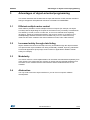
1.1
Where to find the information you need
Technical information about the MC SDK is organized by topic. The following is a list of the
documents that are available and the subjects they cover:
•
•
User manual UM1052: “STM32F PMSM single/dual FOC SDK” provides the following:
–
Features
–
Architecture
–
Workspace
–
Customization processes
–
Overview of algorithms implemented (FOC, current sensors, speed sensors,
embedded analog topologies supported)
–
MC API
–
Demonstrative user project
–
Demonstrative LCD user interface
–
Demonstrative serial communication protocol
User manual UM1053: “Advanced developers guide for STM32F MCUs PMSM
single/dual FOC library” provides the following:
–
Object-oriented programming style used for developing the MC library
–
Description of classes that belong to the MC library
–
Interactions between classes
–
Description of tasks of the MC application
•
MC library source documentation (Doxygen-compiled HTML file). This provides a full
description of the public interface of each class of the MC library (methods, parameters
required for object creation).
•
MC Application source documentation (Doxygen-compiled HTML file). This provides a
full description of the classes that make up the MC API.
•
User Interface source documentation (Doxygen-compiled HTML file). This provides a
full description of the classes that make up the UI Library.
•
STM32F0xx, STM32F10x, STM32F2xx, STM32F30x, or STM32F4xx Standard
Peripherals Library source documentation (Doxygen-compiled HTML file).
•
ST MC Workbench GUI documentation. This is a field guide that describes the steps
and parameters required to customize the library, as shown in the GUI.
•
In-depth documentation about particular algorithms (sensorless position/speed
detection, flux weakening, MTPA, feed-forward current regulation).
Please contact your nearest ST sales office or support team to obtain the documentation
you are interested in if it was not already included in the software package you received or
available on the ST web site (www.st.com).
DocID18459 Rev 8
7/36
35
Documentation architecture
1.2
UM1053
Related documents
Available from www.arm.com
•
Cortex®-M0 Technical Reference Manual, available from: http://infocenter.arm.com.
•
Cortex®-M3 Technical Reference Manual, available from: http://infocenter.arm.com
•
Cortex®-M4 Technical Reference Manual, available from: http://infocenter.arm.com.
Available from www.st.com or your STMicroelectronics sales office
8/36
•
STM32F051x datasheets
•
STM32F100xx datasheet
•
STM32F103xx datasheet
•
STM32F20x and STM32F21x datasheets
•
STM32F40x and STM32F41x datasheets
•
STM32F051x reference manual (RM0091)
•
STM32F100xx reference manual (RM0041)
•
STM32F103xx reference manual (RM0008)
•
STM32F20x and STM32F21x reference manual (RM0033)
•
STM32F40x and STM32F41x reference manual (RM0090)
•
STM32F103xx AC induction motor IFOC software library V2.0 (UM0483)
•
STM32 and STM8 Flash Loader demonstrator (UM0462)
•
STM32F302xB/C datasheet
•
STM32F303xB/C datasheet
•
STM32F30x reference manual (RM0316)
DocID18459 Rev 8
UM1053
2
Object-oriented programming (OOP)
Object-oriented programming (OOP)
Object Oriented Programming (OOP) is a programming paradigm whose roots can be
traced to the 1960s. When the software started to become more complex, researchers
studied ways to organize it in units in order to achieve a high level of modularity and code
reusability. As a result, a new way of programming was conceived, which is able to
decompose programs into self-sufficient modules (classes), each instance (object) of which
containing all the information needed to manipulate its own internal data (representing the
object state).
For more information on OOP, refer to the abundant literature on the subject, and to
Section 7: Bibliography. A description of OOP fundamental concepts and features is
provided here.
Object
An object is a bundle of data structure (members) and functions (methods) allowed to
operate on the data structure itself. The data structure contains both object properties and
variables and can also be referenced as the state of the object.
Class
A class can be considered as the factory from which individual objects are created. It is the
user-defined data type that contains variables, properties and methods.
Method
A method is an operation that can access the internal state of an object by reading and/or
writing its variables and properties. It is important to point out that only an object method can
modify its variables; the object internal variables are hidden to object users, who can
interact with them only through the object methods. This fundamental principle of OOP is
known as data encapsulation or data hiding.
Inheritance
Inheritance is the process through which a class inherits the member and the methods of
another class. This type of relationship is called child-parent or derived-base class. Derived
(child) classes are a more specialized version of the base (parent) class as they inherit
attributes and behavior from the base (parent) class but can also introduce their own.
For example, a class speed sensor might have subclasses called encoder, hall and state
observer. Supposing that speed sensor classes define a method called GetElSpeedDpp that
exports the related internal variable, all of its derived classes inherit this method and the
related internal variable, so that the programmer only needs to write it once (and to link to it
once).
In addition to speed sensor class methods, encoder, hall and state observer can have their
own method (IsObserverConverged, for example) and their own implementation of base
class methods through the so-called virtual functions. This way, the user can always call a
base class method, CalcElectricalAngle for example, without knowing the implementation
done in the derived class.
DocID18459 Rev 8
9/36
35
Object-oriented programming (OOP)
UM1053
Interface
Objects define their interaction with the outside world through the methods that they expose.
The list of methods exported to the application level that operate on that object (class)
constitute the only interface of that object (class).
10/36
DocID18459 Rev 8
UM1053
3
Advantages of object-oriented programming
Advantages of object-oriented programming
This section describes the fundamental concepts and features of OOP, and the benefits of
this type of approach with particular reference to STM32 FOC PMSM SDK.
3.1
Efficient multiple motor control
OOP makes it possible to create multiple instances of objects (for example, two object
encoders) without duplicating the footprint of the Flash memory necessary to handle them.
This efficiency of OOP, in terms of code size, is even more marked when exploiting
inheritance. Taking the example discussed in the previous section as a reference, the
GetElSpeedDpp method is linked in the executable only once, no matter how many
instances have been created of the derived classes encoder, hall or state observer.
3.2
Increased safety through data hiding
Object variables are bound to the object and only accessible through the object methods.
This prevents the object variables from being accidentally modified, improving robustness
for the final applications (fuel pumps, electric traction or applications related to human
safety, for example).
3.3
Modularity
The source code for a class implementation can be written and maintained separately from
other classes. This means that new versions of classes may be released separately from
the others on the condition that the class interface and the method behavior are not
modified.
3.4
Abstraction
You only need to know the object interface so you can focus on specific software
developments.
DocID18459 Rev 8
11/36
35
STM32 PMSM FOC FW library C implementation of OOP
4
UM1053
STM32 PMSM FOC FW library C implementation of
OOP
As a result of its desirable characteristics (code portability and efficiency, ability to access
specific hardware addresses, low runtime demand on system resources, for example), the
C language is widely used in embedded system applications. On the other hand, the C
language, unlike more complex languages such as C++ and Java, does not support objectoriented programming. For this reason, a dedicated implementation of OOP has been
developed in C for the STM32 PMSM FOC FW library.
4.1
Generic classes source files organization and content
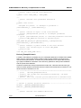
Depending on the proposed implementation, an Example class is generally composed of
three source files:
ExampleClass.h
Located in the \MC library interface folder, this is the public header file that contains the
interface of the Example class. As mentioned previously, the interface of a class exports the
definitions of the methods applicable to the objects of that class. In general, in the STM32
PMSM FOC FW library implementation, this file contains everything necessary to work with
that class. For this purpose, this file contains the public definition of the class type (CEXMP)
and the type structure containing the constant parameters required for the object creation
(ExampleParams_t).
In addition, and only if necessary, definitions of certain types required for using methods are
stored in this file.
/******************************************************************
* @file
ExampleClass.h
* @author IMS Systems Lab and Technical Marketing - MC Team
* @version V0.0.1
* @brief
This file contains interface of Example class
*******************************************************************
*/
/* Includes -----------------------------------------------------*/
#include "MC_type.h"
/**
* @brief Public Example class definition
*/
typedef struct CEXMP_t *CEXMP;
/**
* @brief Example class parameters definition
*/
typedef const struct
{
unsigned int paramA; /*!< Example of parameter */
}ExampleParams_t, *pExampleParams_t;
12/36
DocID18459 Rev 8
UM1053
STM32 PMSM FOC FW library C implementation of OOP
/**
* @brief Creates an object of the class Example
* @param pExampleParams pointer to an Example parameters
structure
* @retval CEXMP new instance of Example object
*/
CEXMP EXMP_NewObject(pExampleParams_t pExampleParams);
/**
* @brief Example of public method of the class Example
* @param this related object of class CEXMP
* @retval none
*/
void EXMP_Func(CEXMP this);
/**
* @brief Example of virtual method of the class Example
implemented by derived class
* @param this related object of class CEXMP
* @retval none
*/
void EXMP_VFunc(CEXMP this);
It is worth noticing that CEXMP class type is a pointer to a void structure (whose type is
CEXMP _t). This prevents the user of the class from accessing object members and hidden
data.
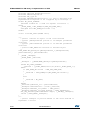
ExamplePrivate.h
Located in \MC library\inc (available only for confidential distribution of STM32 FOC PMSM
SDK), this is a class private header file that contains private definitions required by the class
implementation. It contains definitions of object data structure type (object variable elements
of this structure), virtual methods container structure (only for classes with derived, see next
paragraph), parameters class private re-definition and the private class definition.
/**
*******************************************************************
* @file
ExamplePrivate.h
* @author IMS Systems Lab and Technical Marketing - MC Team
* @version V0.0.1
* @brief This file contains private definition of Example class
*******************************************************************
*/
/**
* @brief Example class members definition
*/
typedef struct
{
unsigned int base_vars; /*!< Example of member */
}Vars_t,*pVars_t;
/**
DocID18459 Rev 8
13/36
35
STM32 PMSM FOC FW library C implementation of OOP
UM1053
* @brief Redefinition of parameter structure
*/
typedef ExampleParams_t Params_t, *pParams_t;
/**
* @brief Virtual methods container
*/
typedef struct
{
void (*pIRQ_Handler)(void *this, unsigned char flag); /*!< Only if
class implementation requires to be
triggered by an interrupt */
void (*pVFunc)(CEXMP this); /*!< Example of virtual function
pointer */ }Methods_t,*pMethods_t;
/**
* @brief Private Example class definition
*/
typedef struct
{
Methods_t Methods_str ;/*!< Virtual methods container */
Vars_t Vars_str; /*!< Class members container */
pParams_t pParams_str; /*!< Class parameters container */
void *DerivedClass;/*!< Pointer to derived class */
}_CEXMP_t, *_CEXMP;
If either the base or derived class implementation requires the execution of program lines to
be triggered by an interrupt, a pointer to those program lines (pIRQ_Handler) is also
defined. See Section 4.4: Motor control library related interrupt handling for more
information about MC library IRQ handler management.
ExampleClass.c
Located in \MC library\src (available only for confidential distribution of STM32 FOC PMSM
SDK), this is the source file that contains the implementation of class methods. This file
includes both the interface and the private definitions of the same class.
The Example_NewObject method merits some explanation. This method creates objects of
Example class (CEXMP) on demand.
Two different implementations of Example_NewObject are proposed, depending on the
availability of the MC_CLASS_DYNAMIC in MCLibraryConf.h definition. If
MC_CLASS_DYNAMIC is defined, the dynamic RAM allocation is enabled and objects are
created through calloc standard library subroutine, resulting in an efficient exploitation of the
RAM memory. This approach is not compatible with MISRA C 2004 rules compliance, due
to the potential risks of memory leaks and memory corruption introduced by the dynamic
memory allocation.
On the contrary, the dynamic memory allocation is disabled when the user comments the
MC_CLASS_DYNAMIC definition. In this case, an array of objects is statically and
previously allocated in the RAM. The list of objects that are reserved for each of the classes
is defined in MCLibraryConf.h for both single motor and dual motor (MAX_EXMP_NUM and
similar). In order to prevent the compiler from reserving RAM memory for objects that will
never be created, you can edit pool dimension accordingly to the final application.
14/36
DocID18459 Rev 8
UM1053
STM32 PMSM FOC FW library C implementation of OOP
Pool dimension tailoring is only permitted in STM32 FOC PMSM SDK confidential
distribution. In case of a web distribution, no additional objects can be instanced by the user.
Only the following exceptions are allowed: up to 3 PID objects, up to 5 PI objects, up to 5
digital output objects.
/**
*******************************************************************
* @file
ExampleClass.c
* @author IMS Systems Lab and Technical Marketing - MC Team
* @version V0.0.1
* @brief
This file contains interface of Example class
*******************************************************************
*/
#include
#include
#include
#include
"ExampleClass.h"
"ExamplePrivate.h"
"MCLibraryConf.h"
"MC_type.h"
#ifdef MC_CLASS_DYNAMIC
#include "stdlib.h" /* Used for dynamic allocation */
#else
_CEXMP_t EXMPpool[MAX_EXMP_NUM];
unsigned char EXMP_Allocated = 0u;
#endif
/**
* @brief Creates an object of the class Example
* @param pExampleParams pointer to an Example parameters
structure
* @retval CEXMP new instance of Example object
*/
CEXMP EXMP_NewObject(pExampleParams_t pExampleParams)
{
_CEXMP _oEXMP;
#ifdef MC_CLASS_DYNAMIC
_oEXMP = (_CEXMP)calloc(1u,sizeof(_CEXMP_t));
#else
if (EXMP_Allocated < MAX_EXMP_NUM)
{
_oEXMP = &EXMPpool[EXMP_Allocated++];
}
else
{
_oEXMP = MC_NULL;
}
#endif
_oEXMP->pParams_str = (pParams_t)pExampleParams;
return ((CEXMP)_oEXMP);
}
/**
DocID18459 Rev 8
15/36
35
STM32 PMSM FOC FW library C implementation of OOP
UM1053
* @brief Example of public method of the class Example
* @param this related object of class CEXMP
* @retval none
*/
void EXMP_Func(CEXMP this)
{
((_CEXMP)this)->Vars_str.base_vars = 0u;
}
/**
* @brief Example of virtual method of the class Example implemented
by derived *
class
* @param this related object of class CEXMP
* @retval none
*/
void EXMP_VFunc(CEXMP this)
{
((_CEXMP)this)->Methods_str.pVFunc(this);
}
4.2
Inheritance implementation
As discussed previously, inheritance is one of the fundamental features of object-oriented
programming. This section describes how it has been achieved in the STM32 PMSM FOC
SDK.
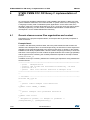
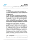
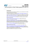
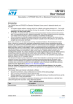
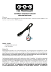
Figure 1 summarizes the private content of a generic class in the proposed implementation.
Figure 1. Generic class structure
Not used in classes with no derived class objects, virtual methods structure and pointers to
derived classes are keys to understanding inheritance accomplishment. Virtual methods
structure contains a list of pointers to those functions that - once properly initialized in the
derived class object creation process - link virtual methods exported by base class interface,
together with their private implementation contained in each of the derived classes.
16/36
DocID18459 Rev 8
UM1053
STM32 PMSM FOC FW library C implementation of OOP
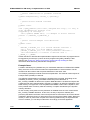
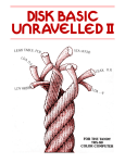
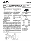
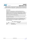
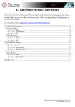
The pointer to a derived class object allows composing a derived class object by merging
both its base and derived class portions as shown in Figure 2.
Figure 2. Derived class object private structure
The derived class portion of a derived class object is always accessed through its base
class portion, which represents the public entry point for both base and derived class
specific members.
4.3
Derived classes source file organization and content
In order to complete the picture of derived class source files, templates are shown here for
the Derived class, derived from the base class Example.
Derived_ExampleClass.h
Located in \MC library interface, this is the public header file that contains the interface of
the Derived_Example class. As for ExampleClass.h, this header file contains everything
necessary to work with the related class. This file contains methods specific of the derived
class, the public definition of the derived class type and the type structure that contains the
constant parameters required to create the derived class object.
In addition and only if necessary, this file contains definitions of certain types required for
using methods.
Creating a new instance of a derived class object requires pointers to both base and derived
classes parameter structures (see also Derived_ExampleClass.c).
/**
*******************************************************************
* @file
Derived_ExampleClass.h
* @author IMS Systems Lab and Technical Marketing - MC Team
* @version V0.0.1
* @brief
This file contains interface of Derived class
*******************************************************************
*/
#include "MC_type.h"
/**
DocID18459 Rev 8
17/36
35
STM32 PMSM FOC FW library C implementation of OOP
UM1053
* @brief Public Derived class definition
*/
typedef struct CDRV_EXMP_t *CDRV_EXMP;
/**
* @brief Derived class parameters definition
*/
typedef const struct
{
unsigned int param1; /*!< Example of parameter */
}DerivedParams_t, *pDerivedParams_t;
/**
* @brief Creates an object of the class Derived
* @param pExampleParams pointer to an Example parameters
structure
* @param pDerivedParams pointer to a Derived parameters structure
* @retval CDRV_EXMP new instance of Derived object
*/
CDRV_EXMP DRV_NewObject(pExampleParams_t pExampleParams,
pDerivedParams_t pDerivedParams);
/**
* @brief Example of public method of the class Derived
* @param this related object of class CDRV_EXMP
* @retval none
*/
void DRV_Func(CDRV_EXMP this);
Derived_ExamplePrivate.h
Located in \MC library\inc (available only for confidential distribution of STM32 FOC PMSM
SDK), this is a class private header file that contains private definitions required for the
derived class implementation. It contains the private definition of an object data structure
type (object variables are elements of this structure), parameter class private redefinition
and the private class definition.
Unlike the related base class private definition header file, a derived class structure type
does not contain pointers to both further derived classes and virtual method containers. This
limits the levels of inheritance to one.
/** ***************************************************************
* @file
Derived_ExamplePrivate.h
* @author IMS Systems Lab and Technical Marketing - MC Team
* @version V0.0.1
* @brief
This file contains private definition of Derived class
*******************************************************************
*/
/* Define to prevent recursive inclusion ------------------------*/
#ifndef __DERIVED_EXAMPLEPRIVATE_H
#define __DERIVED_EXAMPLEPRIVATE_H
/**
* @brief
18/36
Derived class members definition
DocID18459 Rev 8
UM1053
STM32 PMSM FOC FW library C implementation of OOP
*/
typedef struct
{
unsigned int derived_Vars; /*!< Example of member */
}DVars_t,*pDVars_t;
/**
* @brief Redefinition of parameter structure
*/
typedef DerivedParams_t DParams_t, *pDParams_t;
/**
* @brief Private Derived class definition
*/
typedef struct
{
DVars_t DVars_str;/*!< Derived class members container */
pDParams_t pDParams_str;/*!< Derived class parameters container
*/
}_DCDRV_EXMP_t, *_DCDRV_EXMP;
Derived_ExampleClass.c
Located in \MC library\src (available only for confidential distribution of STM32 FOC PMSM
SDK), this is the source file that contains the implementation of both derived class specific
methods and base class virtual methods. It includes both base and derived classes
interface and private definitions. If the derived class requires the execution of program lines
to be triggered by an interrupt, the MCIRQHandlerPrivate.h file is also included (refer to
Section 4.4: Motor control library related interrupt handling for further information about
interrupt handling).
The DRV_NewObject method merits mentioning. This method creates objects of the
Derived_Example class (CDRV_EXMP) on demand and requires the pointers to both
parameters structure of base and derived classes as input. The creation of a derived class
object encloses the creation of the related base class object. The two objects are then
merged by initializing the base class pointer to the derived class object (_oExample>DerivedClass) with the address of the newly created derived class object (_oDerived). The
base class pointers to the virtual methods and—if any—to the MC IRQ Handler are also
initialized with pointers to derived class private functions. The address of the base class
portion of the derived class object is cast to the public derived class type (CDRV_EXMP)
and returned.
/** ***************************************************************
* @file
Derived_ExampleClass.c
* @author IMS Systems Lab and Technical Marketing - MC Team
* @version V0.0.1
* @brief This file contains private implementation of Derived
class
*******************************************************************
*/
#include "ExampleClass.h"
#include "ExamplePrivate.h"
#include "Derived_ExampleClass.h"
DocID18459 Rev 8
19/36
35
STM32 PMSM FOC FW library C implementation of OOP
UM1053
#include "Derived_ExamplePrivate.h"
#include "MCLibraryConf.h"
#include "MC_type.h"
#include "MCIRQHandlerPrivate.h" /*!< Only if derived class
implementation requires to be triggered by an interrupt */
#ifdef MC_CLASS_DYNAMIC
#include "stdlib.h" /* Used for dynamic allocation */
#else
_DCDRV_EXMP_t DRV_EXMPpool[MAX_DRV_EXMP_NUM];
unsigned char DRV_EXMP_Allocated = 0u;
#endif
static void DRV_VFunc(CEXMP this);
/**
* @brief Creates an object of the class Derived
* @param pExampleParams pointer to an Example parameters
structure
* @param pDerivedParams pointer to an Derived parameters
structure
* @retval CDRV_EXMP new instance of Derived object
*/
CDRV_EXMP DRV_NewObject(pExampleParams_t pExampleParams,
pDerivedParams_t pDerivedParams)
{
_CEXMP _oExample;
_DCDRV_EXMP _oDerived;
_oExample = (_CEXMP)EXMP_NewObject(pExampleParams);
#ifdef MC_CLASS_DYNAMIC
_oDerived = (_DCDRV_EXMP)calloc(1u,sizeof(_DCDRV_EXMP_t));
#else
if (DRV_EXMP_Allocated < MAX_DRV_EXMP_NUM)
{
_oDerived = &DRV_EXMPpool[DRV_EXMP_Allocated++];
}
else
{
_oDerived = MC_NULL;
}
#endif
_oDerived->pDParams_str = pDerivedParams;
_oExample->DerivedClass = (void*)_oDerived;
_oExample->Methods_str.pVFunc = &DRV_VFunc;
_oExample->Methods_str.pIRQ_Handler = &DRV_IRQHandler;
Set_IRQ_Handler(pDerivedParams->IRQno, (_CMCIRQ)_oExample);
return ((CDRV_EXMP)_oExample);
}
/**
* @brief Example of private method of the class Derived to
implement a virtual
20/36
DocID18459 Rev 8
UM1053
STM32 PMSM FOC FW library C implementation of OOP
*
function of class Example
* @param this related object of class CEXMP
* @retval none
*/
static void DRV_VFunc(CEXMP this)
{
((_DCDRV_EXMP)(((_CEXMP)this)->DerivedClass))>DVars_str.derived_Vars = 0u;
}
/**
* @brief Example of public method of the class Derived
* @param this related object of class CDRV_EXMP
* @retval none
*/
void DRV_Func(CDRV_EXMP this)
{
((_DCDRV_EXMP)(((_CEXMP)this)->DerivedClass))>DVars_str.derived_Vars = 0u;
}
/**
* @brief Example of private method of the class Derived to
implement an MC IRQ function
* @param this related object
* @param flag used to distinguish between various IRQ sources
* @retval none
*/
static void DRV_IRQHandler(void *this, unsigned char flag)
{
if (flag==1u)
{
((_DCDRV_EXMP)(((_CEXMP)this)->DerivedClass))>DVars_str.derived_Vars++;
}
}
4.4
Motor control library related interrupt handling
The implementation of certain classes (such as speed or current sensors) may require the
execution of specific program lines (referenced below as MC IRQ Handler) when a specific
event occurs, exploiting the related Interrupt Service Routine (ISR).
The same ISR must also be available at the User project level (see also UM1052) to permit
the customization of an application software by adding personal code lines in the same ISR.
In order to keep the motor control library and the user project layers separate, it is
necessary to implement a mechanism that enables triggering the execution of MC IRQ
Handlers bundled within a given class without permitting any explicit reference to the motor
control library objects from the user layer.
With this mechanism, the stm32fxxx_MC_it.c module (containing the definitions of all the
IRQ Handlers that require certain MC code lines to be executed) is put at the disposal of the
user by including it at the user project level. Both the stm32fxxx_MC_it.c and the motor
control libraries include a module, MCIRQHandlerClass, which privately holds a motor
DocID18459 Rev 8
21/36
35
STM32 PMSM FOC FW library C implementation of OOP
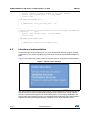
UM1053
control vector table (MC_IRQTable) that contains the set of objects that need to be triggered
by an ISR. The filling of a given position in the table is performed when the corresponding
object is created (inside the related XXX_New_Object method) by means of the
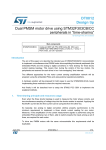
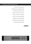
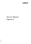
Set_IRQ_Handler function call. Figure 3 illustrates this process.
Figure 3. Motor control interrupt handling
When an interrupt event occurs, the related ISR (Peripheral_X_IRQHandler) is accessed.
After clearing the proper interrupt flag and optionally executing user defined code lines, the
Exec_IRQ_Handler function is called if it is required to execute an MC IRQ Handler.
In order to identify the MC IRQ Handler to be executed, the MC_IRQTable position that
corresponds to the proper object is passed as a function parameter (so stm32fxxx_MC_it.c
does not require object interface knowledge). Furthermore, as an MC IRQ Handler can be
generally accessed from more than one interrupt, a flag that identifies the triggering event is
also passed.
Once the object owner of the MC IRQ Handler to be executed has been identified by
accessing the MC IRQ Table in the position passed to Exec_IRQ_Handler, this function can
finally jump to the MC IRQ Handler itself.
The entire process, considering the program flow from the Peripheral_X_IRQHandler to the
MC IRQ Handler, only requires two jumps: to Exec_IRQ_Handler and then to the MC IRQ
Handler. In this way, the overhead introduced by the SW architecture is minimized. This is
achieved by making the addresses of both the object and its related MC IRQ Handler (which
is located in the first element of the class structure, as already shown in ExamplePrivate.h
template) the same.
22/36
DocID18459 Rev 8
UM1053
5
How to create a user-defined class
How to create a user-defined class
Users can create their own classes and add them to the motor control library. To do this, use
the templates described in Section 4.1 for base classes and Section 4.3 for derived classes.
If the newly created class requires the execution of an MC IRQ Handler on an interrupt
occurrence, the MAX_MC_IRQ_NUM definition in MCIRQHandlerClass.c must be
incremented and the corresponding MC IRQ table position defined, by adding the following
line in MCIRQHandlerClass.h, for example:
#define MC_IRQ_USER_IRQ
Note:
4u
The first four table positions are reserved for PWMnCurrFdbk (first and second instances)
and SpeednPosFdbk (first and second instance) objects. In case of STM32 FOC PMSM
SDK web distribution, the maximum number of elements for the MC IRQ table is limited to 8
(elements 0 to 3 are already reserved and not available for the user, elements 4 to 7 are left
for the user).
Add the Exec_IRQ_Handler(MC_IRQ_USER_IRQ, flag) function call in stm32fxxx_MC_it.c
in the proper peripheral IRQ handler. The flag is the identifier for the interrupt trigger event.
DocID18459 Rev 8
23/36
35
STM32 PMSM FOC FW library class list
6
UM1053
STM32 PMSM FOC FW library class list
This section provides a general view and a short description of the classes used in the MC
library. For a detailed description of the methods and parameters of each class, see STM32
FOC PMSM FW library v4_1 developer Help file.chm.
Note:
Source files of the MC library classes are only provided free of charge within STM32 FOC
PMSM SDK confidential distribution. Contact your nearest ST sales office or support team
for further information.
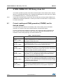
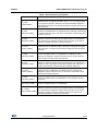
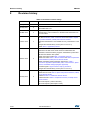
6.1
Current reading and PWM generation (CPWMC) and its
derived classes
This class implements both the functionality of the current reading sensor and PWM
generator. Any object of this class must be linked to a derived class object.
In order to increase the modularity of the library, the access to the MCU peripherals has
been moved to the derived classes, which have been additionally differentiated by the
hardware current sensing topology. The derived classes are:
Table 1. Derived classes
Class
24/36
Definition
R1_VL1
(CR1VL1_PWMC)
Current sensing carried out via a single shunt resistor placed on the DC
bus link and implemented on an STM32F100x MCU (value line devices). It
only supports a single motor drive.
R1_LM1
(CR1LM1_PWMC)
Current sensing carried out via a single shunt resistor and implemented on
an STM32F103x MCU; where, x= 4, 6, 8, B (performance line, low and
medium density devices). It only supports a single motor drive.
R1_HD2
(CR1HD2_PWMC)
Current sensing carried out via a single shunt resistor and implemented on
an STM32F103x MCU; where, x= C, D, E (performance line, high density
devices). Although it is designed to support dual motor drive, it can also be
used when a single motor drive has been instanced.
R3_LM1
(CR3LM1_PWMC)
Current sensing carried out via three shunt resistors placed below low side
switches on the three inverter legs and implemented on an STM32F103x
MCU; where, x= 4, 6, 8, B (performance line, low and medium density
devices). It only supports a single motor drive.
R3_HD2
(CR3HD2_PWMC)
Current sensing carried out via three shunt resistors placed below low side
switches on the three inverter legs and implemented on an STM32F103x
MCU; where, x= C, D, E (performance line, high density devices). Although
it is designed to support dual motor drive, it can also be used when a single
motor drive has been instanced.
ICS_LM1
(CILM1_PWMC)
Current sensing carried out through isolated current sensors and
implemented on an STM32F103x MCU; where, x= 4, 6, 8, B (performance
line, low and medium density devices). It only supports a single motor
drive.
DocID18459 Rev 8
UM1053
STM32 PMSM FOC FW library class list
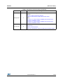
Table 1. Derived classes (continued)
Class
Definition
ICS_HD2
(CIHD2_PWMC)
Current sensing carried out through isolated current sensors and
implemented on an STM32F103x MCU; where, x= C, D, E (performance
line, high density devices). Although it has been specifically designed to
support dual motor drive, it can also be used when a single motor drive has
been instanced.
R1_F2XX
(CR1F2XX_PWMC)
Current sensing carried out via a single shunt resistor placed on the DC
bus link and implemented on an STM32F2xx MCU. Although it is designed
to support dual motor drive, it can also be used when a single motor drive
has been instanced.
R3_F2XX
(CR3F2XX_PWMC)
Current sensing carried out via three shunt resistors placed below low side
switches on the three inverter legs and implemented on an STM32F2xx
MCU. Although it is designed to support dual motor drive, it can also be
used when a single motor drive has been instanced.
ICS_F2XX
(CIF2XX_PWMC)
Current sensing carried out through isolated current sensors and
implemented on an STM32F2xx MCU. Although it is designed to support
dual motor drive, it can also be used when a single motor drive has been
instanced.
R1_F4XX
(CR1F4XX_PWMC)
Current sensing carried out via a single shunt resistor placed on the DC
bus link and implemented on an STM32F40x or STM32F41x MCU.
Although it is designed to support dual motor drive, it can also be used
when a single motor drive has been instanced.
R3_F4XX
(CR3F4XX_PWMC)
Current sensing carried out via three shunt resistors placed below low side
switches on the three inverter legs and implemented on an STM32F40x or
STM32F41x MCU. Although it is designed to support dual motor drive, it
can also be used when a single motor drive has been instanced.
ICS_F4XX
(CIF4XX_PWMC)
Current sensing carried out through isolated current sensors and
implemented on an STM32F40x or STM32F41x MCU. Although it is
designed to support dual motor drive, it can also be used when a single
motor drive has been instanced.
R1_F0XX
(CR1F0XX_PWMC)
Current sensing carried out via a single shunt resistor placed on the DC
bus link and implemented on an STM32F0xx. It only supports a single
motor drive.
R1_F30X
(CR1F30XX_PWMC)
Current sensing carried out via a single shunt resistor placed on the DC
bus link and implemented on an STM32F30x.
Current sensing carried out via three shunt resistors placed below low side
switches on the three inverter legs and implemented on an STM32F30x
R3_4_F30X
MCU. Although it is designed to support dual motor drive, it can also be
(CR3_4F30XX_PWMC)
used when a single motor drive has been instanced. It make use the
embedded peripheral not sharing the resources.
DocID18459 Rev 8
25/36
35
STM32 PMSM FOC FW library class list
UM1053
Table 1. Derived classes (continued)
Class
Definition
Current sensing carried out via three shunt resistors placed below low side
switches on the three inverter legs and implemented on an STM32F30x
R3_2_F30X
MCU. Although it is designed to support dual motor drive, it can also be
(CR3_2F30XX_PWMC)
used when a single motor drive has been instanced. It make use the
embedded peripheral sharing the resources.
Current sensing carried out via three shunt resistors placed below low side
R3_1_F30X
switches on the three inverter legs and implemented on an STM32F30x
(CR3_1F30XX_PWMC) MCU. It make use of a single ADC peripheral to perform two successive
current sampling. It only supports a single motor drive.
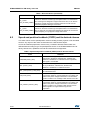
6.2
Speed and position feedback (CSPD) and its derived classes
This class carries out the speed/position sensor handling for both physical or FW emulated
sensors. Any object of this class must be linked to a derived class object.
Access to hardware peripherals, if there is any, is asked to derived classes which are
differentiated according to type of speed/position sensor. In the STM32 PMSM FOC FW
library, hall sensors, quadrature encoder and sensorless are supported:
Table 2. Speed and position feedback (CSPD) and its derived classes
Class
26/36
Definition
ENCODER (CENC_SPD)
This derived class supports quadrature encoder and can be
used with any STM32F0x, STM32F100x, STM32F103x,
STM32F2x, STM32F40x or STM32F41x MCU. By default,
index signal is not handled.
HALL (CHALL_SPD)
This derived class supports three hall sensors. It can be used
with any STM32F0x, STM32F100x, STM32F103x,
STM32F2x, STM32F40x or STM32F41x MCU.
HALL_F30X (CHALL_F30X_SPD)
This derived class supports three hall sensors. It can be used
with STM32F30x MCU.
STO (CSTO_SPD)
This derived class implements sensorless rotor position
reconstruction based on current feedbacks, bus voltage and
applied motor phase voltages information. The sensorless
algorithm consists of a Luenberger state observer and a PLL.
STO_CORDIC (CSTOC_SPD)
This derived class implements sensorless rotor position
reconstruction based on current feedbacks, bus voltage and
applied motor phase voltages information. The sensorless
algorithm consists of a Luenberger state observer and an
iterative algorithm for trigonometric arctg function
computation.
DocID18459 Rev 8
UM1053
STM32 PMSM FOC FW library class list
Table 2. Speed and position feedback (CSPD) and its derived classes (continued)
Class
6.3
Definition
Virtual speed sensor (CVSS_SPD)
This derived class is mainly used during ramp-up if an object
of one of the sensorless speed/position classes (CSTO_SPD
or CSTOC_SPD) is used as a main speed sensor. Used in
conjunction with a rev-up controller and a speed and torque
controller, it allows customizing ramp-up. An object of this
class emulates a real sensor during motor rev up by returning
(on demand) a virtual angle and/or a virtual speed in
accordance with the time base and the acceleration (set by
derived class specific method VSPD_SetMecAcceleration).
High frequency injection speed
sensor (CHFI_FP_SPD)
This derived class implement sensorless rotor position
reconstruction based on high frequency injection technique
for I-PMSM motors (specific for STM32F3xx and F4xx series
exploiting the floating point support).
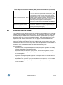
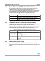
Additional method classes
A set of classes have be developed to provide specific functionalities that can be optionally
enabled to achieve specific performances such as: flux weakening, Maximum-Torque-PerAmpere (MTPA) for I-PMSM motors, feed-forward current regulation and high frequency
injection (to work with HFI speed and position feedback). All of these classes have been
implemented and available for the user. In the user project these are instantiated and
clocked properly according the setup done by the ST MC Workbench. Moreover other two
classes are available to perform the open loop voltage mode control (useful to debug the
hardware before to run the motor in FOC) and a class that implements the circle limitation of
the voltage vector alpha-beta according the maximum modulation index.
Each of these classes can implement one or more of the following methods used in the
current regulation:
•
XX_CalcCurrRef, it computes the Iqdref according the specific algorithm. It is usually
clocked at the frequency of speed regulation.
•
XX_PreProcessing, that perform a pre process, before current regulation, on FOC
related variables, according the specific algorithm. It is usually clocked at the frequency
of current regulation.
•
XX_VqdConditioning, that manipulate the Vqd vector, computed by the current
regulators, according the specific algorithm to be implemented. It is usually clocked at
the frequency of current regulation.
•
XX_DataProcess, it perform a post process, after current regulation, on FOC related
variables, according the specific algorithm. It is usually clocked at the frequency of
current regulation.
DocID18459 Rev 8
27/36
35
STM32 PMSM FOC FW library class list
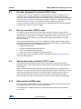
6.4
UM1053
Bus voltage sensor (CVBS) and its derived classes
This class implements either a virtual or a real bus voltage, depending on the sensor
availability. Any object of this class must be linked to a derived class object.
If any, the access to MCU peripherals is delegated to the derived classes so that the base
class implementation is kept hardware-independent. Derived classes are differentiated
according to the type of physical sensor and microcontrollers family (if any):
Table 3. Bus voltage sensor (CVBS) and its derived classes
Class
6.5
Description
Rdivider (CRVBS_VBS)
Derived class which can handle all types of real voltage sensor with
analog output. For example, hardware resistive voltage partitioning.
Virtual (CVVBS_VBS)
Derived class which emulates a voltage sensor when no real sensors are
available. It always returns a constant programmable voltage.
Temperature sensor (CTSNS) and its derived classes
This class implements either a virtual or real temperature sensor, depending on the sensor
availability. Any object of this class must be linked to a derived class object.
If any, the access to MCU peripherals is delegated to the derived classes so that the base
class implementation is kept hardware-independent. Derived classes are differentiated
according to the type of physical sensor and microcontrollers family (if any):
Table 4. Temperature sensor (CTSNS) and its derived classes
Class
6.6
Description
NTC (CNTC_TSNS)
Derived class which can handle NTC sensor or more in general analog
temperature sensors whose output is related to the temperature by the
following formula:
dV
V out = V 0 + ------- • ( T – T 0 )
dT
Virtual (CVTS_TSNS)
Derived class which emulates a temperature sensor when no real sensors
are actually available. It always returns a constant programmable
temperature.
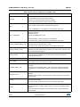
Digital Output (CDOUT) class
This class is used to abstract the concept of digital output driving from its hardwaredependent implementation. With particular reference to motor control, this class can be
used to drive in-rush current limiter devices or handle resistive brake turn-on and turn-off, for
example.
28/36
DocID18459 Rev 8
UM1053
6.7
STM32 PMSM FOC FW library class list
Encoder Alignment Controller (CEAC) class
This class is only used if a quadrature encoder is used as a main or auxiliary sensor. In
conjunction with a virtual speed sensor, a speed and torque controller and FOC drive
objects, this class handles the initial encoder calibration (which comprises a rotor alignment
in a given position) necessary to make the information coming from a quadrature encoder
absolute. See Section 6.4 for more information about the alignment procedure.
In case of a dynamic allocation, the object may be destroyed after the alignment has been
executed, and created only when necessary.
6.8
Rev-up controller (CRUC) class
This class is only used if an object of one of the sensorless classes is used as a main
speed/position sensor. Used in conjunction with a speed and torque controller and a virtual
speed sensor, this class enables a complete customization of the motor phase current
waveforms during motor ramp-up. This class is also used to implement the “on-the-fly”
sensorless startup.
In the present implementation, the rev-up is divided into smaller portions called phases,
where both speed and current amplitude can vary linearly. Each phase is characterized by
its parameters (structure type RUCPhasesParams_t):
•
duration (hDurationms)
•
final motor speed (hFinalMecSpeed01Hz)
•
final current amplitude (hFinalTorque)
•
pointer to the next rev-up phase parameters structure.
The Initial angle for the first phase can also be specified. See also Section 6.2 for more
information about ramp-up.
6.9
Speed and torque controller (CSTC) class
The speed and toque controller provides a FOC object with a target electrical torque
depending on the control mode (speed or torque control) and executes target speed and
torque ramps.
When in speed mode, the speed and toque controller computes the new target speed
reference, if a ramp is being executed, and then performs the speed regulation loop. The
return is an electrical torque, which is then used by the FOC object to get Iqref and Idref.
When the speed and toque controller is in torque mode, it computes the new target
electrical torque, if a ramp is being executed, and then returns a target electrical torque.
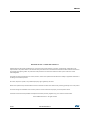
6.10
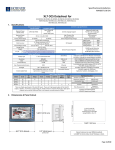
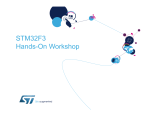
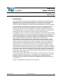
State machine (STM) class
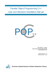
The state machine class handles transitions between the states of the drive that influence
the actions that need to be taken by motor control tasks.
The following list of available states and a summarizing block diagram are provided for
convenience.
DocID18459 Rev 8
29/36
35
STM32 PMSM FOC FW library class list
UM1053
Table 5. State machine (STM) class available states
State
Description
ICLWAIT
Persistent state, the system is waiting for ICL deactivation.
It is not possible to run the motor if ICL is active.
Until the ICL is active the state is forced to ICLWAIT,
when ICL become inactive the state is moved to IDLE
IDLE
Persistent state. The following state can be:
– IDLE_START, if a start motor command has been given
or
– IDLE_ALIGNMENT, if a start alignment command has been given
IDLE_ALIGNMENT
“Pass-through” state containing the code to be executed only once after encoder
alignment command.
Next states can be:
– ALIGN_CHARGE_BOOT_CAP
or
– ALIGN_OFFSET_CALIB according the configuration.
It can also be ANY_STOP if a stop motor command has been given.
ALIGN_CHARGE_BOOT_CAP
Persistent state where the gate driver boot capacitors will be charged.
Next states will be ALIGN_OFFSET_CALIB.
It can also be ANY_STOP if a stop motor command has been given.
ALIGN_OFFSET_CALIB
Persistent state where the offset of motor currents measurements will be
calibrated. Next state will be ALIGN_CLEAR. It can also be ANY_STOP if a stop
motor command has been given.
ALIGN_CLEAR
“Pass-through” state in which object is cleared and set for the startup.
Next state will be ALIGNMENT. It can also be ANY_STOP if a stop motor
command has been given.
ALIGNMENT
IDLE_START
Persistent state in which the encoder are properly aligned to set mechanical
angle, following state can only be ANY_STOP.
CHARGE_BOOT_CAP
“Pass-through” state contains the code to be executed only once after start motor
command.
Next states can be CHARGE_BOOT_CAP or OFFSET_CALIB according the
configuration. It can also be ANY_STOP if a stop motor command has been
given.
OFFSET_CALIB
Persistent state where the offset of motor currents measurements will be
calibrated.
Next state will be CLEAR. It can also be ANY_STOP if a stop motor command
has been given.
CLEAR
“Pass-through” state in which object is cleared and set for the startup.
Next state will be START.
It can also be ANY_STOP if a stop motor command has been given.
START
Persistent state where the motor start-up is intended to be executed.
The following state is normally START_RUN as soon as first validated speed is
detected.
Another possible following state is ANY_STOP if a stop motor command has
been executed.
30/36
DocID18459 Rev 8
UM1053
STM32 PMSM FOC FW library class list
Table 5. State machine (STM) class available states (continued)
State
Description
START_RUN
“Pass-through” state, the code to be executed only once between START and
RUN states its intended to be here executed.
Following state is normally RUN but it can also be ANY_STOP if a stop motor
command has been given.
RUN
Persistent state with running motor. The following state is normally ANY_STOP
when a stop motor command has been executed.
ANY_STOP
“Pass-through” state, the code to be executed only once between any state and
STOP its intended to be here executed. Following state is normally STOP.
STOP
Persistent state. Following state is normally STOP_IDLE as soon as conditions
for moving state machine are detected
STOP_IDLE
“Pass-through” state, the code to be executed only once between STOP and
IDLE its intended to be here executed. Following state is normally IDLE
FAULT_NOW
Persistent state, the state machine can be moved from any condition directly to
this state by STM_FaultProcessing method.
This method also manage the passage to the only allowed following state that is
FAULT_OVER
FAULT_OVER
Persistent state where the application is intended to stay when the fault
conditions disappeared.
Following state is normally STOP_IDLE, state machine is moved as soon as the
user has acknowledged the fault condition.
Figure 4. State machine flow diagram
)$8/7
29(5
6723
,'/(
,&/:$,7
,'/(
$1<
6723
6723
,'/(
67$57
)$8/7
12:
2))6(7
&$/,%
&/($5
67$57
$/,*1
&/($5
$/,*1
67$57
581
581
&+$5*(
%227
&$3
,QUXVK
FXUUHQWOLPLWHU
$/,*1
2)6(7
&$/,%
,'/(
$/,*1
$/,*1
&+$5*(
%227
&$3
(QFRGHUDOLJQPHQW
06Y9
DocID18459 Rev 8
31/36
35
STM32 PMSM FOC FW library class list
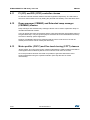
6.11
UM1053
PI (CPI) and PID (CPID) controller classes
PI and PID controller classes realize PI and PID regulators respectively. The PID class is
seen as a derived class from PI by adding the particular functionality of the derivative terms.
6.12
Ramp manager (CRMNG) and Extended ramp manager
(CREMNG) classes
Ramp manager and extended ramp manager classes can be used to implement ramps of
variables with defined duration.
User can define final value and duration and the class interpolate the intermediate values of
the generated ramp. They are general purpose classes that can be instantiated and used by
the users to develop specific application.
Number of available instances are defined inside the source code and is 4 for both as
default (some of them can be used by MC firmware).
6.13
Motor profiler (CSCC) and One touch tuning (COTT) classes
“Motor profiler” and “One touch tuning” classes implements the relative features and will be
used together when enabled by WB to run an unknown motor from the scratch.
Once the procedure has been executed it is possible to get information about motor
electrical parameter using the exported methods. (See Help file.chm for further
informations).
32/36
DocID18459 Rev 8
UM1053
7
Bibliography
Bibliography
[1] Armstrong, The Quarks of Object-Oriented Development. In descending order of
popularity, the “quarks” are: Inheritance, Object, Class, Encapsulation, Method, Message
Passing, Polymorphism, Abstraction.
[2] Pierce, Benjamin (2002). MIT Press. ISBN 0-262-16209-1, section 18.1 “What is ObjectOriented Programming?”.
[3] John C. Mitchell, Concepts in programming languages, Cambridge University Press,
2003, SBN 0-521-78098-5, p.278.
[4] Michael Lee Scott, Programming language pragmatics, Edition 2, Morgan Kaufmann,
2006, ISBN 0-12-633951-1, p. 470.
[5] Abadi, Martin; Cardelli, Luca (1996). A Theory of Objects. Springer-Verlag New York,
Inc.. ISBN 0387947752. Retrieved 2010-04-21.
DocID18459 Rev 8
33/36
35
Revision history
8
UM1053
Revision history
Table 6. Document revision history
Date
Revision
08-Apr-2011
1
Initial release.
24-May-2011
2
Added references for web and confidential distributions of STM32
FOC PMSM SDK v3.0
28-Mar-2012
3
The product range has been expanded from “STM32F103xx or
STM32F100xx” microcontrollers to “STM32F100x/103x/2x/40x/41x”
microcontrollers.
4
Added “STM32F05xx" to the product range, which has impacted the
title, the Introduction, Table 1: Derived classes and Table 2: Speed
and position feedback (CSPD) and its derived classes.
Replaced “STM32F40xx” and “STM32F41xx” by “STM32F4xx” in the
title.
Changed the software library version (from v3.2 to v3.3).
Added Table 1: Applicable products.
5
Added STM32F30xx inside product range.
Replaced in the title and in whole document STM32F05x with
STM32F0x, because the library supports “STM32F03x" product also.
UM1052 and UM1053 Title update
Added new product inside Table 1: Applicable products.
Added rows inside Table 1: Derived classes and Table 2: Speed and
position feedback (CSPD) and its derived classes.
Added “embedded analog topologies supported” in Table –:
Overview of algorithms implemented (FOC, current sensors, speed
sensors, embedded analog topologies supported).
Re-loaded figure 6 Figure 6: Motor ramp-up procedure.
Changed the software library version (from v3.3 to v3.4).
6
Changed software library version from v3.4 to v4.0.
Added last row inside Table 2: Speed and position feedback (CSPD)
and its derived classes.
Modified Section 6.3: Additional method classes.
Modified the title of Table 4: Temperature sensor (CTSNS) and its
derived classes.
Removed Chapter 7 (Class interaction)
Removed Chapter 8 (Description of task)
14-Nov-2012
02-Dec-2013
19-May-2014
34/36
Changes
DocID18459 Rev 8
UM1053
Revision history
Table 6. Document revision history (continued)
Date
25-May-2015
11-Sep-2015
Revision
Changes
7
Changed software library version from v4.0 to v4.1.
Updated
– Figure 4: State machine flow diagram
– Table 5: State machine (STM) class available states
Added:
– Section 6.12: Ramp manager (CRMNG) and Extended ramp
manager (CREMNG) classes
– Section 6.12: Ramp manager (CRMNG) and Extended ramp
manager (CREMNG) classes
8
Updated
– Introduction
– Table 1: Derived classes
– Table 6.5: Temperature sensor (CTSNS) and its derived classes
DocID18459 Rev 8
35/36
35
UM1053
IMPORTANT NOTICE – PLEASE READ CAREFULLY
STMicroelectronics NV and its subsidiaries (“ST”) reserve the right to make changes, corrections, enhancements, modifications, and
improvements to ST products and/or to this document at any time without notice. Purchasers should obtain the latest relevant information on
ST products before placing orders. ST products are sold pursuant to ST’s terms and conditions of sale in place at the time of order
acknowledgement.
Purchasers are solely responsible for the choice, selection, and use of ST products and ST assumes no liability for application assistance or
the design of Purchasers’ products.
No license, express or implied, to any intellectual property right is granted by ST herein.
Resale of ST products with provisions different from the information set forth herein shall void any warranty granted by ST for such product.
ST and the ST logo are trademarks of ST. All other product or service names are the property of their respective owners.
Information in this document supersedes and replaces information previously supplied in any prior versions of this document.
© 2015 STMicroelectronics – All rights reserved
36/36
DocID18459 Rev 8