1
EE 155/255 Lab #2
Revision 1, September 28, 2015
Lab2: Energy Meter
In this lab, youll build and program a meter that measures voltage, current, power, and energy at DC and AC.
Assigned: September 28, 2015
Due: Week of October 5, 2015
Part 1
New Code
Pull the latest code from the class Github repo using git pull. If you are working on a private repository you will have to run git pull upstream master assuming you have mapped a remote to the
class repository. If you haven’t set up a remote repository for the class Github you can through the command git remote add upstream https://github.com/ndanyliw/green-electronics.git.
The lab starter files will be under ‘labs/lab2/’.
For this lab, you should be able to do everything by editing lab2.c and lab2.h. Code is already provided to
read and write calibration data in EEPROM.
Part 2
Analog to Digital Conversion
To measure power delivered to the load, you need to measure the voltage across the load and current through
the load nearly simultaneously. Circuitry is provided to convert the load voltage and current into voltages
which are safe for the microcontroller to measure.
The STM32F303 has 4x12-bit 5 Msps ADCs connected to 39 external channels. There are many modes in
which these ADCs can be operated and controlled. For those who are curious please check out the chip
datasheet and user manual. The EE155 library operates in a dual conversion mode which allows capturing
data simultaneously on converter channels. This allows measuring things like current and voltage at the
same time so you can calculate instantaneous power. The reference for the ADCs is set to 3V so analog
signals will have to range between 0-3V to be converted properly.
The converters are set to operate in a single ended mode so a result of 0 corresponds to 0V and 0xfff is 3V.
On the fast channels the conversions take 0.19 µs. This can be sped up to 0.16 µs if reducing the resolution
to 10 bits.
The EE155 libraries provide a very simplified interface to the ADCs with a small subset of their possible functionality. To fully utilize the converters on the board you will have to expand on the libraries’ functionality
using STM’s abstraction libraries (check out stm32f30x adc.h/c).
Part 2 continued on next page. . .
Page 1 of 6
EE 155/255 Lab #2
Revision 1, September 28, 2015
Part 2 (continued)
For a good overview on the ADCs check out the STM32F3 ADC PDF in the Github repository.
ADC Initialization
Before you can use the ADCs, you will have to initialize the library. The command is adc init(). This
command sets up the ADC registers and prepares them for conversion.
To set the sampling frequency use adc set fs(float fs). This will set up TIM2 to trigger the ADC at
the appropriate intervals.
Setting up Channels
The ADC library is configured to use specified channels for carrying out the conversions. What external pins
these map to can be found in the ge adc.c source. To enable a channel use the adc enable channel(int
chan) function which will enable the specified channel on both ADC1 and ADC2.
After enabling the channels you will need to specify callback functions for them which can be done through
adc callback(const int chan, void (*callback)(uint t32)). The callback function takes in
a 32 bit integer which is the results of ADC2 and ADC1 concatenated {ADC2, ADC1}.
Starting Conversions
After configuring the ADC library, to actually start conversions use adc start() which will launch the
timer and begin conversions. To stop the converter use adc stop().
Processing Results
The results of each conversion will be passed to the callback functions. If your processing is fast enough you
can parse the results in that function. Otherwise you should save the data to a global variable and process
it later.
ADC example
Listing 1: ADC example code
/**
* Calculate power using the ADCs
*/
5
10
#include "ge_adc.h"
//volts per division
#define V_PER_DIV .0025
//amps per division
#define A_PER_DIV .001
Part 2 continued on next page. . .
Page 2 of 6
EE 155/255 Lab #2
Revision 1, September 28, 2015
Part 2 (continued)
//ADC callbacks
void calculate_power(uint32_t data);
15
f l o a t power_result;
//initialize ADCs
adc_init();
20
//set sampling frequency at 50kHz
adc_set_fs(50000);
//add callback to channel 1
adc_callback(1, &calculate_power);
25
//enable channel 1
adc_enable_channel(1);
30
//start ADCs
adc_start();
//wait for interrupts
while (1) {};
35
void calculate_power(uint32_t data) {
uint16_t chan1 = data & 0x00ff;
uint16_t chan2 = (data & 0xff00) >> 16;
power_result = ( f l o a t ) chan1 * V_PER_DIV * ( f l o a t ) chan2 * A_PER_DIV;
40
}
Part 3
Hardware
Your energy meter should be able to measure 200V and 10A, for a total instantaneous power of 2kW. It
should work on both DC and AC.
Our power and energy meter connects between a power source and a load. The meter senses the load voltage
VL by measuring the voltage between the positive and negative load terminals. The meter senses the load
current by measuring the current that flows from LOAD- to SOURCE-.
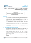
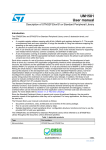
A schematic of our power and energy meter is shown in 1. Most of the component values are left for you to
calculate as a lab exercise. The meter uses our microprocessor module for analog measurement and display,
the current sense resistor on the component module to measure the load current, and an operational amplifier
to amplify the voltage across the current sense resistor.
The current sense resistor RS is on the component board, which has terminals for using various passive
Part 3 continued on next page. . .
Page 3 of 6
EE 155/255 Lab #2
Revision 1, September 28, 2015
Part 3 (continued)
high-power parts. All of the circuit except RS, R1, and R2 should be built on a breadboard and powered
from the control module. There are two sets of terminals for RS: the large terminals connect to the source
and load, while the small header terminals connect to the energy meter circuit.
Figure 1: The energy meter sits between a source and a load. It connects between the source and the load
on the negative side.
Two analog inputs of the processor module, A0 and A1, are used to sense the load voltage and current
respectively. A voltage divider composed of resistors R1 and R2 scales the load voltage VL to the 0-2.5V
input range of the processors ADC. The voltage divider of R7 and R8 should set the zero-input voltage on
A0 and A1 to 1.25V (the center of the ADC range) to allow bipolar (positive and negative) measurement.
The RS = 10m current sense resistor connected between NL and NS converts the 10A load current into a
100mV voltage. We connect LOAD- to processor ground so that our voltage measurement is the voltage
across the load, which differs from the voltage across the source by the amount dropped across the current
sense resistor. We use operational amplifier U1A connected as a differential amplifier to amplify the 100mV
voltage across the sense resistor to fit the 2.5V input range of the ADC. We use a differential amplifier
here, rather than a single-ended inverting or non-inverting amplifier, to cancel any noise that exists between
LOAD- and the actual processor ground. The gain of this amplifier is set by the choice of resistor values. For
simplicity, set R4=R6 and R3=R5. Capacitor C2 forms a low-pass filter with R5 to reduce high-frequency
noise that may be above half the ADC sampling rate.
Since R1 has a high voltage connected to it, the connections on R1 and R2 must be solid and reliable. This
voltage divider should be soldered together. R1 should be at least 100k.
Page 4 of 6
EE 155/255 Lab #2
Revision 1, September 28, 2015
Part 3
Part 4
Filtering
A common and simple approach to smoothing signals is to use a one-pole IIR filter: yn = αyn1 + βx where
β
the DC gain is xy = (1α)
.
We want α to be slightly less than one to provide a low-pass response. To keep the implementation fast
1
and simple, well choose α = 1 − 2shif
t and β = 1, where shif t is some integer > 0. This can be written as:
yn−1
yn = yn−1 − 2shif t + x
The DC gain is xy = 2shif t , so to produce unity gain the output needs to be divided by 2shif t . These divisions
can be done with bit shifts if working with integers, so they are fast.
You will need to write filtering functions for your power meter to avoid excess noise on the readings.
Part 5
Calibration
The ADC measurements are not perfect, and the resistor values used in the voltage divider and currentsense circuit are not exact. The result is that 0V and 0A will not typically produce an ADC value of 2047,
and other voltages will not produce exactly what you expected when you calculated the resistor values. To
correct for this, you need to measure at least two points to find the conversion from ADC counts to voltage
or current.
Since any change to the circuitry could change the offset or scale, the calibration procedure needs to be simple
and automated. To do this, add a special mode to your program to measure 0V, 0A, a known voltage, and
a known current. Make the known values small enough to be safely handled when testing but large enough
to avoid excessive rounding error (a single ADC count is not a good choice). Set CAL VOLTS and CAL CURR
in lab2.h to the values you choose. The defaults are 10V and 3A.
The main loop provided to you uses pushbutton 1 to select among four screens: live measurements, calibrating
offset, and calibrating voltage and current scale factors. Pressing the pushbutton 2 in a calibration screen
causes one of the calibrate *() functions to be called, which is where you should calculate and store the
new calibration data.
Calibration data is stored in EEPROM so you dont have to recalibrate every time you turn on the meter.
meter init() reads this calibration data from EEPROM and the calibrate *() functions write it back
to EEPROM when its updated.
Page 5 of 6
EE 155/255 Lab #2
Revision 1, September 28, 2015
Part 5
Part 6
Testing
Use a heating element as the load. This device is almost purely resistive and can dissipate lots of power
(enough to burn you, so dont touch it after you start delivering significant power to it). For a DC supply,
use one of the 100V 10A power supplies. Demonstrate that your energy meter correctly measures the power
and energy delivered to the load for three different operating points. Apply a known amount of power for a
known amount of time and verify that the total energy delivered is as predicted. How accurate is your meter?
How much error does it show under heavy load (1kW) and under no load? Use the infrared thermometer to
measure the temperature of the load after delivering 1kJ.
Signoffs
1. Show DC power and energy measurements for at least three different operating points.
Show correct four-quadrant measurements:
1. Exchange the source and the load to invert the current.
2. Exchange the source terminals to invert the voltage.
Page 6 of 6