1
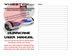
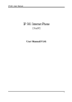
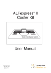
autolube electronic lubrication control unit
Introduction
Specifications
General Precautions
Keypad Layout
Panel Description
Single Line System with pressure switch
Single Line System Fault Indication
Optional Equipment
Page 2
Page 3
Page 4
Page 5
Page 6
Page 9
Page 19
Page 21
cyc
SLS
SETUP
sec
min
hrs
ENTER
RUN
PAUSE
PUMP
PROXY 1
PROXY 2
RESERVOIR
Fuse
Autolube
+ -
+ - + - - +
TX RX
M RES
P2 P1 IGN
12V
24V
-
8Amp
Autolube
cyc
r .5
SETUP
INTRODUCTION
AUTOLUBE CONTOLLER MANUAL
autolube electronic lubrication control unit
manual setup procedures
sec
min
hrs
ENTER
RUN
PAUSE
PUMP
PROXY 1
PROXY 2
RESERVOIR
Fuse
SUBJECT TO CHANGE WITHOUT PRIOR NOTICE
Autolube
+ -
+ - + - - +
TX RX
M RES
P2 P1 IGN
12V
24V
-
8Amp
Contact us: - Tel: +27 21 551 7496 - Fax: +27 21 551 7495 - email: [email protected] - url: www.ultra-flow.com
2
The AUTOLUBE is a universal lubrication system controller capable of handling all common lubrication
systems from the simplest run - pause timer through progressive, single and dual line systems. Innovative
algorithms also give new flexibility and greater control over traditional single line systems.
SPICIFICATIONS
AUTOLUBE CONTOLLER MANUAL
autolube specifications
The practical layout gives clear indication of exactly what is happening at any time and the advantaged
diagnostics will help to pinpoint any faults quickly. Although highly flexible, it remains simple to operate and
program by using Ultra-Flow’s proprietary Lube-Logic© setup procedure. By specifying what type of system is
being used, Lube-Logic© asks the user only relevant information in a clear step by step manner and the
operator need only concern himself with the particular system he is using.
The built in Real Time Clock allows the unit to log a history of operations and faults conditions. Serial
communications allows the operation / history and setup to be modified / altered via a PC. By using the GSM
option available, all conditions can be monitored remotely using GSM cellular network and the unit can even be
programmed to report any fault conditions to a remote PC located elsewhere in the country or in a different
country.
FEATURES:
!
!
!
!
!
!
!
!
!
!
!
!
!
!
!
!
!
!
!
Runs progressive, single line and dual line lubrication systems.
Real time clock logs date and time of faults ( 80 critical records).
RS232 serial port allows connection to PC.
Option to connect to GSM modem allowing remote monitoring via GSM networks.
Optional Dongle available for remote downloading of data without the need of a Laptop.
Timing intervals from 5 seconds to 24 hours.
Cycle Counting.
10Vdc to 30Vdc operation.
Short circuit/open circuit detection with audible warning.
External fault lamp drive (Flash or steady output)
Low level reservoir monitoring.
Two sensor switch inputs.
Visual & audible fault indication.
Non-volatile memory.
Built in "blown fuse" indicator.
3 digit LED display indicates exact status of system.
Simple "Lube Logic" setup procedure.
Test mode allows testing of all the circuits connected to the Autolube for verifying.
Practical attractive housing with mounting bracket.
SUBJECT TO CHANGE WITHOUT PRIOR NOTICE
SPECIFICATIONS:
VOLTAGE:
CURRENT DRAIN:
PUMP OUTPUT:
LAMP OUTPUT:
SWITCHING:
FUSE:
CONNECTION:
COMMUNICATIONS:
DIMENSIONS:
WEIGHT:
PROTECTION:
TEMPERATURE RANGE:
10VDC TO 30VDC
150ma MAX (no load) 70ma nominal
7A rms.MAX
3A MAX
Solid state short circuit protected
8 Amp fast blow 20mm glass
14 way MOLEX MINIFIT - JR
RS232 Type
70mm X 145mm X 38mm (including mounting bracket)
300g
IP54
-25C to 80C
Contact us: - Tel: +27 21 551 7496 - Fax: +27 21 551 7495 - email: [email protected] - url: www.ultra-flow.com
3
The user manual is intended to familiarize the user with the autolube controller and its designated use. The
operating instructions contain important information on how to operate the autolube controller safely, properly
and efficiently. Observing these instructions will help reduce confusion and actual damage to the autolube
controller. This manual must be read and applied by any person in charge of carrying out any form of setting up or
work on the autolube controller.
GENERAL PRECATIONS
AUTOLUBE CONTOLLER MANUAL
general precautions
Operational Precautions:
Includes the total understanding of the autolube specifications. Never connect to any other voltage supply other
than that specified in the manuals contained within.
The owner/user must ensure at all times that installation or inspections are executed by authorized and qualified
personnel who have thoroughly read the operating instruction manual.
Any setting up or work on the autolube controller must be done while the machine is off. The machine must be in
such a position that it will not cause harm to any person should the machine be switched on for the setting up of the
autolube controller.
In the event that the machine needs to be on for the setting up of the autolube controller it must be on condition that
the operator or personnel working on the machine are advised.
Never switch the machine on without the prior knowledge of the operator/owner or somebody that has full
knowledge of the machines operation.
Warnings:
SUBJECT TO CHANGE WITHOUT PRIOR NOTICE
Never weld on a machine while the main switch of the machine is on. Insure that the machines main switch is off
and correctly tagged. Welding on a machine can cause serious damage to the autolube controller.
Do not alter or modify any part of the autolube controller.
Insure that the autolube controller in mounted in an suitable area.
Do not mount the autolube controller near excessive heat area's.
Always use the right specified fuse rating for the autolube controller.
Never exceed the voltage rating of the autolube controller.
Never expose the autolube controller to direct sunlight.
Never expose the autolube controller to water or other substances.
MANUFACTURER:
Ultra-Flow Lubrication Systems c.c.
Email technical inquiries - [email protected]
Contact us: - Tel: +27 21 551 7496 - Fax: +27 21 551 7495 - email: [email protected] - url: www.ultra-flow.com
4
Mounting Bracket
KEY PAD LAYOUT
AUTOLUBE CONTOLLER MANUAL
autolube key pad layout
LED Display
Cycle Indicator
Setup Indicator
System Reset & Pump Run
P.
SETUP
cyc
2
sec
min
hrs
Enter Program
Led Pump on Green & Red when faulty
ENTER
Minute Indicator
Hour Indicator
Select value down or silent buzzer
RUN
PAUSE
Led Sensor 1 selected & Red when Faulty
Second Indicator
Buzzer
PUMP
PROXY 1
Led Sensor 2 selected & Red when Faulty
PROXY 2
RESERVOIR
Fuse
Led Low Level selected & Red when faulty
Autolube
Blown Fuse Indicator
Fuse Holder 8A
+ -
+ - + - - +
TX RX
M RES
P2 P1 IGN
12V
24V
-
8Amp
Ignition Negative & Positive
RS 232 Connection
SUBJECT TO CHANGE WITHOUT PRIOR NOTICE
Ignition to Standby Mode
Sensor 1 Positive & Negative
Pump motor Connection
Reservoir Sensor Connection
External Lamp
Sensor 2 Positive & Negative
Contact us: - Tel: +27 21 551 7496 - Fax: +27 21 551 7495 - email: [email protected] - url: www.ultra-flow.com
5
SETUP
sls
PANEL DISPLAY
AUTOLUBE CONTOLLER MANUAL
panel description
cyc
sec
SLS = Single Line Systems
min
hrs
SETUP
Pls
cyc
sec
min
PLS = Progressive Line Systems
hrs
SETUP
dls
cyc
sec
min
DLS = Dual Line Systems
hrs
SETUP
n-o
cyc
sec
min
N-O = Normally Open (Sensors)
hrs
SETUP
n-c
cyc
sec
min
N-C = Normally Closed (Sensors)
hrs
SETUP
l-s
cyc
sec
min
L-S = External Lamp Steady (Continues supply)
SUBJECT TO CHANGE WITHOUT PRIOR NOTICE
hrs
SETUP
l-f
cyc
sec
min
L-F = External lamp Flashing (Pulsed Supply)
hrs
SETUP
nfe
cyc
sec
min
NFE = Non Fatal Error (Pump Continues on Low Level
Fault)
hrs
Contact us: - Tel: +27 21 551 7496 - Fax: +27 21 551 7495 - email: [email protected] - url: www.ultra-flow.com
6
SETUP
r. 5
PANEL DISPLAY
AUTOLUBE CONTOLLER MANUAL
panel description
cyc
sec
R = Run Time in Cycles
min
hrs
SETUP
P. 3 2
cyc
sec
min
P = Pause Time in Sec, Min or Hrs
hrs
SETUP
f. 20
cyc
sec
min
F = Fault Time in Sec, Min or Hrs
hrs
SETUP
U. 26
cyc
sec
min
U = Vent Time in Sec, Min or Hrs
hrs
SETUP
Rcc
cyc
sec
min
RCC = Run Cycle Counter
hrs
SETUP
YES
cyc
sec
min
YES = Yes for accepting program changes
SUBJECT TO CHANGE WITHOUT PRIOR NOTICE
hrs
SETUP
Tst
cyc
sec
min
TST = Test Mode for Checking Installed Devices
hrs
SETUP
T. 4 0
cyc
sec
min
T = Time out or Dwell Time for Sensors
hrs
Contact us: - Tel: +27 21 551 7496 - Fax: +27 21 551 7495 - email: [email protected] - url: www.ultra-flow.com
7
SETUP
PANEL DISPLAY
AUTOLUBE CONTOLLER MANUAL
panel description
cyc
fe
sec
NE = Fatal Error (Pumps Stops on Low Level Fault)
min
hrs
SETUP
cyc
no
sec
min
NO = Do Not Select Selection
hrs
SETUP
cyc
r29
sec
min
R = Run Time in Secs, Mins and Hours
hrs
SETUP
.
cyc
sec
min
. = Standby Mode
SUBJECT TO CHANGE WITHOUT PRIOR NOTICE
hrs
Contact us: - Tel: +27 21 551 7496 - Fax: +27 21 551 7495 - email: [email protected] - url: www.ultra-flow.com
8
single line system using a pressure switch
cyc
sls
SETUP
SINGLE LINE SETUP
AUTOLUBE CONTOLLER MANUAL
manual setup for single line systems
sec
min
hrs
ENTER
RUN
PAUSE
PUMP
PROXY 1
PROXY 2
RESERVOIR
Fuse
SUBJECT TO CHANGE WITHOUT PRIOR NOTICE
Autolube
+ -
+ - + - - +
TX RX
M RES
P2 P1 IGN
12V
24V
-
8Amp
Contact us: - Tel: +27 21 551 7496 - Fax: +27 21 551 7495 - email: [email protected] - url: www.ultra-flow.com
9
single line system using a pressure switch
SINGLE LINE SETUP
AUTOLUBE CONTOLLER MANUAL
manual setup for single line systems
STEP 1
cyc
PLS
SETUP
sec
min
hrs
ENTER
RUN
PAUSE
To enter the setup mode of the autolube controller
press the ENTER button, hold and keep depressed
while switching on the ignition switch or any other
power source to the controller. Let go the ENTER
button and the red LED (Setup) should now be
illuminated. The green LED on the description
PUMP will be flashing. PLS (Progressive Line Systems)
should also appear in the display.
2
PUMP
PROXY 1
PROXY 2
RESERVOIR
Fuse
Autolube
+ -
+ - + - - +
TX RX
M RES
P2 P1 IGN
12V
24V
-
8Amp
STEP 2
cyc
sLS
SETUP
sec
min
hrs
SUBJECT TO CHANGE WITHOUT PRIOR NOTICE
ENTER
To select what type of system you require press the
RUN/PAUSE (up) button and this will change the type
of system required. By pressing the UP button the next
system displayed will be SLS (Single Line Systems),
the next system displayed after that would be DLS
(Dual Line Systems). Continue to press the UP button
till SLS is displayed. This procedure will enter into the
Single Line Mode.
2
RUN
1
PAUSE
PUMP
PROXY 1
PROXY 2
RESERVOIR
Fuse
Autolube
+ -
+ - + - - +
TX RX
M RES
P2 P1 IGN
12V
24V
-
8Amp
Contact us: - Tel: +27 21 551 7496 - Fax: +27 21 551 7495 - email: [email protected] - url: www.ultra-flow.com
10
single line system using a pressure switch
SINGLE LINE SETUP
AUTOLUBE CONTOLLER MANUAL
manual setup for single line systems
STEP 3
cyc
sLS
SETUP
sec
Press the ENTER button to accepts SLS.
By pressing the ENTER button you have confirmed
that you want to use Single Line Systems.
min
hrs
ENTER
2
RUN
PAUSE
PUMP
PROXY 1
PROXY 2
RESERVOIR
Fuse
Autolube
+ -
+ - + - - +
TX RX
M RES
P2 P1 IGN
12V
24V
-
8Amp
STEP 4
p
SETUP
cyc
5
sec
min
hrs
As you press the ENTER button P (Pause) will now
appear in the display. By pressing the UP button
you can change the time from any amount in seconds
to minutes then to hours. Note that the Led will change
from seconds then to minutes and finally hours. The
amount in the display will indicate what the pause time
will be.
SUBJECT TO CHANGE WITHOUT PRIOR NOTICE
ENTER
RUN
PAUSE
PUMP
PROXY 1
PROXY 2
RESERVOIR
Fuse
Autolube
+ -
+ - + - - +
TX RX
M RES
P2 P1 IGN
12V
24V
-
8Amp
Contact us: - Tel: +27 21 551 7496 - Fax: +27 21 551 7495 - email: [email protected] - url: www.ultra-flow.com
11
single line system using a pressure switch
SINGLE LINE SETUP
AUTOLUBE CONTOLLER MANUAL
manual setup for single line systems
STEP 5
cyc
P 4. 0
SETUP
sec
Press the ENTER button to accept the pause time.
By pressing the ENTER button you have confirmed
that you want to use a pause time of 4 hours as indicated.
min
hrs
ENTER
2
RUN
PAUSE
PUMP
PROXY 1
PROXY 2
RESERVOIR
Fuse
Autolube
+ -
+ - + - - +
TX RX
M RES
P2 P1 IGN
12V
24V
-
8Amp
STEP 6
R
SETUP
cyc
1
sec
min
hrs
SUBJECT TO CHANGE WITHOUT PRIOR NOTICE
ENTER
Note that when using Single line Systems the RUN
time will default to that of cycles. In the display it
would either show 99 cycles or what ever cycles was
setup before. In this example we are going to setup
1 cycle. The unit will only look for 1 signal from the
pressure switch before going into VENT time.
Press the ENTER button to accept and proceed to
the next setup procedure.
2
RUN
PAUSE
PUMP
PROXY 1
PROXY 2
RESERVOIR
Fuse
Autolube
+ -
+ - + - - +
TX RX
M RES
P2 P1 IGN
12V
24V
-
8Amp
Contact us: - Tel: +27 21 551 7496 - Fax: +27 21 551 7495 - email: [email protected] - url: www.ultra-flow.com
12
single line system using a pressure switch
SINGLE LINE SETUP
AUTOLUBE CONTOLLER MANUAL
manual setup for single line systems
STEP 7
cyc
t 25
SETUP
sec
min
hrs
ENTER
In the display the pressure switch timeout will now be
displayed. Press the up button to increase the duration
of the timeout required. Note on larger systems it may
take longer to pressurize the complete system. It is
important that the system is tested to establish its
timeout. Add around 50% more to the actual timeout
for the system to operate effectively without timing out
before it has reached its pressure status.
Press the ENTER button to accept your settings.
2
RUN
PAUSE
PUMP
PROXY 1
PROXY 2
RESERVOIR
Fuse
Autolube
+ -
+ - + - - +
TX RX
M RES
P2 P1 IGN
12V
24V
-
8Amp
STEP 8
cyc
n-o
SETUP
sec
min
hrs
After you have pressed the ENTER button N - O
(Normally open) will appear in the display. This is
an indication whether your pressure switch is normally
open or normally closed. Press the up button to choose
between N-O or N-C. Press the ENTER button to
accept your choice.
SUBJECT TO CHANGE WITHOUT PRIOR NOTICE
ENTER
2
RUN
1
PAUSE
PUMP
PROXY 1
PROXY 2
RESERVOIR
Fuse
Autolube
+ -
+ - + - - +
TX RX
M RES
P2 P1 IGN
12V
24V
-
8Amp
Contact us: - Tel: +27 21 551 7496 - Fax: +27 21 551 7495 - email: [email protected] - url: www.ultra-flow.com
13
single line system using a pressure switch
SINGLE LINE SETUP
AUTOLUBE CONTOLLER MANUAL
manual setup for single line systems
STEP 9
cyc
no
SETUP
sec
min
hrs
ENTER
After pressing the ENTER button NO (NO) will appear in
the display. Note that the green LED on proxy2 is
now illuminated. Should you want to use a 2nd proxy
then proceed by pushing the up button, press enter
to accept and proceed the setup as you would have
for proxy1. Normally we use only 1pressure switch, press the
up button till NO appears in the display. Press the ENTER
button to accept your choice.
2
1RUN
PAUSE
PUMP
PROXY 1
PROXY 2
RESERVOIR
Fuse
Autolube
+ -
+ - + - - +
TX RX
M RES
P2 P1 IGN
12V
24V
-
8Amp
STEP 10 (VENT TIME)
cyc
U. 1.0
SETUP
sec
min
After you have pressed the ENTER button U (VENT)
will appear in the display. This is an indication of what
the time in seconds, minutes of the actual time it takes
for the system to VENT before proceeding into its
next cycle or pause time.
hrs
It is possible now to setup SLS with multiple cycles.
For example, if you setup your cycles to 2 then the unit
will operate for 1 cycle then go into a VENT time of 1
minute as indicated in the display. After that minute has
elapsed then the pump would turn back on and proceed
with the next cycle. As soon as the second cycle has been
reached then the VENT time (U) would appear in the display
and time itself out for the time that it has been setup for.
SUBJECT TO CHANGE WITHOUT PRIOR NOTICE
ENTER
2
RUN
1
PAUSE
PUMP
PROXY 1
PROXY 2
RESERVOIR
Autolube
+ -
+ - + - - +
TX RX
M RES
P2 P1 IGN
12V
24V
-
8Amp
Fuse
After it has completed the 2 cycles and its VENT time
then only will the unit proceed into its pause time.
For this example we are only using 1 cycle and therefor
only require a short VENT time as no further cycles are
required before reaching its pause sequence.
Press the ENTER button to accept the VENT time and
proceed to the next part of the setup procedure.
Contact us: - Tel: +27 21 551 7496 - Fax: +27 21 551 7495 - email: [email protected] - url: www.ultra-flow.com
14
single line system using a pressure switch
SINGLE LINE SETUP
AUTOLUBE CONTOLLER MANUAL
manual setup for single line systems
STEP 11
cyc
yes
SETUP
sec
min
hrs
ENTER
2
RUN
1
PAUSE
PUMP
PROXY 1
PROXY 2
RESERVOIR
Fuse
Autolube
+ -
+ - + - - +
TX RX
M RES
P2 P1 IGN
After you have pressed the ENTER button NO will appear
in the display. Note that the green LED on reservoir will
now be illuminated. In this setup procedure you have the
choice of selecting low level detection or not. Should you
not require low level detection then push the up button and
select NO. Press the ENTER button to accept.
In this example we are going to select the low level
option. Press the up button till YES appears in the display.
Press the ENTER button to accept your choice.
PLEASE NOTE THAT WHEN USING THE LOW LEVEL
SENSOR, A 10 SECOND DELAY ON STARTUP WILL TAKE
PLACE. THIS IS TO ENSURE THAT THE PADDLE
ASSEMBLY IS IN THE RIGHT POSITION TO THE SENSOR.
AFTER 10 SECONDS OF RUNNING THE SENSOR WILL
IMMEDIATELY ACTIVATE ON LOW LEVEL. THE LOW
LEVEL WARNING WILL BE DISPLAYED WHEN THE UNIT
REACHES ITS PAUSE STATUS. THE UNIT WILL NOT
DISPLAY A LOW LEVEL WARNING WHILE IN RUN MODE.
12V
24V
-
8Amp
STEP 12
cyc
n -o
SETUP
sec
min
SUBJECT TO CHANGE WITHOUT PRIOR NOTICE
hrs
After you have pressed the ENTER button N - O
(Normally open) will appear in the display. This is
an indication whether your sensor is normally open or
normally closed. Press the up button to choose between
N-O or N-C. Press the ENTER button to accept your
choice.
ENTER
2
1RUN
PAUSE
PUMP
PROXY 1
PROXY 2
RESERVOIR
Fuse
Autolube
+ -
+ - + - - +
TX RX
M RES
P2 P1 IGN
12V
24V
-
8Amp
Contact us: - Tel: +27 21 551 7496 - Fax: +27 21 551 7495 - email: [email protected] - url: www.ultra-flow.com
15
single line system using a pressure switch
SINGLE LINE SETUP
AUTOLUBE CONTOLLER MANUAL
manual setup for single line systems
STEP 13
cyc
fe
SETUP
sec
min
hrs
ENTER
2
RUN
1
PAUSE
PUMP
After you have pressed the ENTER button either FE
(Fatal Error) or NFE (Non Fatal Error) will appear in
the display. The option of using FE (Fatal Error) is
for the pump to stop on a low level warning. This is
mostly used on pumps with reservoir capacities of
1L to 10L. It is preferred to stop the pump at low level
in order to maintain a layer of grease above the pump
element area. This would help by not allowing an air
pocket to form around the pump element when filling
up the reservoir.
In the case of NFE (Non Fatal Error) it is mostly used
on larger pump reservoirs whereby the distance of the
pump tube to the bottom of the reservoir is substantial.
Select your choice and press the ENTER button.
PROXY 1
PROXY 2
RESERVOIR
Fuse
Autolube
+ -
+ - + - - +
TX RX
M RES
P2 P1 IGN
12V
24V
-
8Amp
STEP 14
cyc
l- f
SETUP
sec
min
SUBJECT TO CHANGE WITHOUT PRIOR NOTICE
hrs
ENTER
By pressing the up button the status will change from
L - F (Lamp flashing) to L - S (Lamp static).
L - F is a pulsed output supply and L -S is a constant
output supply.
2
1RUN
PAUSE
After pressing the ENTER button L - F (Lamp Flashing)
will appear in the display. This option is for an external
warning lamp to be fitted. Normally if you have any sort
of monitoring installed then this function will be used.
Press the ENTER button to move onto the next part of the
programming.
PUMP
PROXY 1
PROXY 2
RESERVOIR
Fuse
Autolube
+ -
+ - + - - +
TX RX
M RES
P2 P1 IGN
12V
24V
-
8Amp
Contact us: - Tel: +27 21 551 7496 - Fax: +27 21 551 7495 - email: [email protected] - url: www.ultra-flow.com
16
single line system using a pressure switch
STEP 15
cyc
tst
SETUP
sec
min
hrs
ENTER
2
RUN
1
PAUSE
PROXY 1
PROXY 2
RESERVOIR
Autolube
+ -
+ - + - - +
TX RX
M RES
P2 P1 IGN
After pressing the ENTER button TST will appear
in the display. This indicates that you are now in the
test mode of your setup procedure. By pressing the
up button you will note that your pump will now start
turning. Should the pump turn in the wrong direction
it is now possible to correct by changing the polarity
of your wiring. It is possible to check all other sensors
as well by energizing them manually and watching if
the green LED illuminates in that process. If the LED
does not illuminate then there is a problem either
with the wiring or setup procedure.
If all is correct you may turn of the power supply
to the autolube controller.
PUMP
SUBJECT TO CHANGE WITHOUT PRIOR NOTICE
SINGLE LINE SETUP
AUTOLUBE CONTOLLER MANUAL
manual setup for single line systems
Fuse
PLEASE NOTE THAT TST MUST APPEAR IN THE
DISPLAY BEFORE SWITCHING OFF THE POWER
TO THE UNIT. SHOULD YOU SWITCH OFF POWER
TO THE UNIT WHILE IT IS IN ANY PART OF THE
PROGRAMMING THE SYSTEM WILL NOT SAVE YOUR
CHANGES. TST MUST APPEAR IN THE DISPLAY IN
ORDER FOR THE CHANGES TO BE ACCEPTED.
12V
24V
-
8Amp
Contact us: - Tel: +27 21 551 7496 - Fax: +27 21 551 7495 - email: [email protected] - url: www.ultra-flow.com
17
single line system using a pressure switch
SINGLE LINE SETUP
AUTOLUBE CONTOLLER MANUAL
manual setup for single line systems
RUN CYCLE MODE
cyc
r. 1
SETUP
After the power has been terminated on the unit
then switched on again the unit will proceed in its
run mode. All devices teen selected will now be
displayed. Note that after each cycle received
the amount will decrease by 1 until all cycles
have been reached and the unit will proceed to
its pause time.
sec
min
hrs
ENTER
RUN
PAUSE
PUMP
PROXY 1
PROXY 2
RESERVOIR
Fuse
Autolube
+ -
+ - + - - +
TX RX
M RES
P2 P1 IGN
12V
24V
-
8Amp
Running System.(Pump run)
SETUP
r. 1
cyc
sec
min
hrs
When the controller is switched on the
run cycle counter will appear in the display as it
was setup for. The counter will appear from
the actual counts set and count down to zero.
The green LED will indicate that you are in
run cycle counter. The green LED on the pump
function will be flashing indicating that the pump is
now turning or pumping.
SUBJECT TO CHANGE WITHOUT PRIOR NOTICE
Running System.(Pump pause)
SETUP
P. 4.0
cyc
sec
min
hrs
When the controller has reached the required
cycle counts it will go into its pause time that it was
setup for. The pause time will count down from
what it was setup for to zero and then resume
its cycle count. Note that the green LED will be
steady on the pump section of the decal. This
is a indication that the pump is thereby not
turning while it is in the pause mode.
Running System.(Vent time)
SETUP
u. 4.0
cyc
sec
min
hrs
When the controller has reached the required
cycle counts it will go into its VENT time that it was
setup for. The VENT time will count down from
what it was setup for to zero and then resume
itspause cycle. Note that the green LED will be
steady on the pump section of the decal. This
is a indication that the pump is thereby not
turning while it is in the VENT mode.
Contact us: - Tel: +27 21 551 7496 - Fax: +27 21 551 7495 - email: [email protected] - url: www.ultra-flow.com
18
single line system fault indications
Press the RUN/PAUSE
button to reset faults
cyc
f 10
SETUP
FAULT INDICATIONS
AUTOLUBE CONTOLLER MANUAL
manual setup for single line systems
Fault indication. This will
count up from seconds,
minutes till hours. This is
an indication of how long
the fault has been active
sec
min
hrs
Press the Down Button
to silent the buzzer
ENTER
Pump faulty, either a
short circuit or the
wires have come off
RUN
PAUSE
Blown fuse indication
Replace with 8A fuse
PUMP
Proxy 1 fault, either
a faulty pressure switch
or no lube in reservoir.
PROXY 1
PROXY 2
RESERVOIR
SUBJECT TO CHANGE WITHOUT PRIOR NOTICE
Low level fault. Possible
cause, reservoir empty
Fuse
Autolube
+ -
+ - + - - +
TX RX
M RES
P2 P1 IGN
12V
24V
-
8Amp
Change the fuse here
Replace with an 8amp
fuse
NOTE: IN ORDER FOR A FAULT TO BE TOTALLY RESET THE UNIT MUST PERFORM I COMPLETE
CYCLE OF RUN AND PAUSE TO CANCEL AN EXISTING FAULT OUT OF MEMORY. THE UNIT
IS DESIGNED TO MEMORIZE THE TOTAL TIME OF ANY SPECIFIC FAULT. THE ONLY WAY THE UNIT
CAN FUNCTION CORRECTLY WITHOUT THE SAME FAULT OCCURRING IS FOR IT TO RUN 1
COMPLETE CYCLE.
Contact us: - Tel: +27 21 551 7496 - Fax: +27 21 551 7495 - email: [email protected] - url: www.ultra-flow.com
19
WIRING DIAGRAM
AUTOLUBE CONTOLLER MANUAL
manual setup for single line systems
single line system wiring diagram with pressure switch
Power Switch
+ - + - - +
M
RES
P2
P1 IGN
12V
24V
-
8Amp
-
+
Power Supply
+M
Low Level Sensor
SUBJECT TO CHANGE WITHOUT PRIOR NOTICE
External Warning Lamp
Pressure Switch
Contact us: - Tel: +27 21 551 7496 - Fax: +27 21 551 7495 - email: [email protected] - url: www.ultra-flow.com
20
remote data shuttle
OPTIONAL EQUIPMENT
AUTOLUBE CONTOLLER MANUAL
optional equipment autolube controller
AUTOLUBE
DATA
SHUTTLE
CHANNEL
P.
SETUP
cyc
2
sec
min
9
9
hrs
Done
ENTER
Fail
RUN
PAUSE
PUMP
UPLOAD
PROXY 1
PROXY 2
RESERVOIR
Autolube
Fuse
ADS-2
Data Unit
SUBJECT TO CHANGE WITHOUT PRIOR NOTICE
+ -
+ -
+ - + - - +
TX RX
M RES
P2 P1 IGN
TX RX
12V
24V
-
8Amp
The autolube controller has the capacity to store all critical faults up to 80 records. The Data Shuttle is a
device that can retrieve this data without the use of a laptop PC. The data shuttle can retrieve information
from up to 100 different controllers. This information can be then downloaded from the Data Shuttle to your
desktop PC to the autolube program whereby all the relevant faults can be scrutinized.
The Data Shuttle has its own battery power and all information downloaded from the autolube controllers
will be safely stored without the risk of loss.
Contact us: - Tel: +27 21 551 7496 - Fax: +27 21 551 7495 - email: [email protected] - url: www.ultra-flow.com
21
cyc
dls
SETUP
OPTIONAL EQUIPMENT
AUTOLUBE CONTOLLER MANUAL
optional equipment autolube controller
gsm modem
Autolube
GSM
Modem
sec
min
hrs
ENTER
RUN
PAUSE
Receiving Data
PUMP
Uploading Data
PROXY 1
Sim Card Faulty
PROXY 2
Power
RESERVOIR
Fuse
Signal Good
SUBJECT TO CHANGE WITHOUT PRIOR NOTICE
Autolube
+ -
+ - + - - +
TX RX
M RES
P2 P1 IGN
Autolube
12V
24V
+ -
8Amp
TX RX
-
The autolube controller can also communicate together with a GSM modem. This is the ultimate tool
for downloading data from the autolube and more importantly to upload information and settings to the
controller without having to send a technician to site. The gsm modem needs to be installed together
with the autolube controller. The main centre for receiving and uploading of data needs to have a modem
connected to their pc in order to send and receive data. Each modem has its own identity and unique address.
Contact us: - Tel: +27 21 551 7496 - Fax: +27 21 551 7495 - email: [email protected] - url: www.ultra-flow.com
22