1
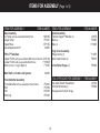
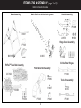
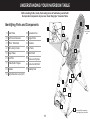
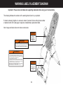
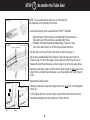
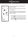
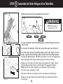
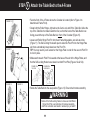
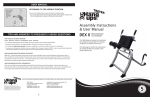
R
700ia Inversion Table
Assembly Instructions
R HANG
TE
5
YEAR
RANT
Y
W
AR
S
UP
TE
E
TM
*Inversion Table images may
vary slightly from your model.
BEFORE YOU BEGIN: Review all steps before beginning assembly and read all precautions before using the inversion table.
Carefully adhere to the Assembly Instructions and Owner’s Manual to help ensure safety and product integrity.
IMPORTANT SAFETY INSTRUCTIONS
READ ALL INSTRUCTIONS BEFORE USING THE INVERSION TABLE.
!
WARNING
WARNING - To reduce the risk of injury to persons:
• Read and understand all the instructions, view the instructional video, review all other accompanying documents, and inspect the
equipment before using the inversion table. It is your responsibility to familiarize yourself with the proper use of this equipment and the
inherent risks of inversion, such as falling on your head or neck, pinching, entrapment, or equipment failure. It is the responsibility of
the owner to ensure that all users of the product are fully informed about the proper use of the equipment and all safety precautions.
• Close supervision is necessary when the inversion table is used near children, or by or near invalids or disabled persons.
• Use the inversion table only for its intended use as described in this manual. DO NOT use attachments not recommended by the
manufacturer.
• NEVER drop or insert any object into any opening.
• DO NOT use or store product outdoors.
• DO NOT use if you are over 6 ft 6 in (198 cm) or over 300 lbs. (136 kg). Structural failure could occur or head/neck may impact the
floor during inversion.
• DO NOT allow children to use this machine.
• Keep children, bystanders, and pets away from machine while in use.
• Keep body parts, hair, loose clothing and jewelry clear of all moving parts.
• The inversion table has no user serviceable parts.
• This product is intended for indoor home use only. DO NOT use in any commercial, rental or institutional setting.
FAILURE TO FOLLOW INSTRUCTIONS AND WARNINGS COULD RESULT IN SERIOUS INJURY OR DEATH.
SAVE THESE INSTRUCTIONS
BEFORE YOU BEGIN: Review all steps before beginning assembly and read all precautions before using the inversion table.
Carefully adhere to the Assembly Instructions and Owner’s Manual to help ensure safety and product integrity.
IMPORTANT SAFETY INSTRUCTIONS
READ ALL INSTRUCTIONS BEFORE USING THE INVERSION TABLE.
!
WARNING
• DO NOT use the equipment without a licensed physician’s approval and a review of the medical contraindications, as noted in the
Owner’s Manual.
• Failure to assemble and/or use the equipment as directed may void the manufacturer’s warranty on this product and could result in
injury or death.
• Choose a level surface for assembling and operating the table.
• Follow each step in sequence. DO NOT skip ahead.
• Make sure that all fasteners are secure.
• ALWAYS test and inspect the table. Make sure the table rotates smoothly to inverted position and back.
• ALWAYS replace defective components immediately and/or keep the equipment out of use until repair.
FAILURE TO FOLLOW INSTRUCTIONS AND WARNINGS COULD RESULT IN SERIOUS INJURY OR DEATH.
SAVE THESE INSTRUCTIONS
ITEMS FOR ASSEMBLY (Page 1 of 2)
ITEMS FOR ASSEMBLY
Base Assembly
A-Frame with pre-assembled Stability Feet
Angle Tether
Head Pillow
Decompression Arch
ITEM NUMBER
TM
NX1105
F51007
EP1105
IA1650
FitFlexTM Table Bed
Upper Portion with pre-assembled Bed Frame Extension IA1310A
Lower Portion with pre-assembled Bed Frame
F11300B
Bolts (2 short, 1 long) & Nuts (3)
F11390
Main Shaft with Ankle Lock System
Front Ankle Bar Assembly
Front Ankle Bar with pre-assembled Foam Rollers
Bolt
Nut
End Cap
ITEMS FOR ASSEMBLY
Handle Assembly
Traction Support Handles (2)
Bolts (2)
Nuts (2)
TM
ITEM NUMBER
IA1670
F51085
H13009
Hinge Cover Assembly
Hinge Covers (2)
Allen Head Screws (4)
F11250
F50075
3-Hole Roller Hinges (2)
F51064
IA1600
TOOLS PROVIDED FOR ASSEMBLY
F51045
F51089
H13009
F51048
3
5mm Allen Wrench Screwdriver
10/13mm Wrenches (2)
Packaged with the Roller Hinges
ITEM NUMBER
IA1149
F51088
ITEMS FOR ASSEMBLY (Page 2 of 2)
Items not shown to scale.
Base Assembly
Main Shaft with Ankle Lock System
Handle Assembly
F51085
F51007
IA1670
Hinge Cover Assembly
EP1105
NX1105
IA1650
H13009
IA1600
F11250
F50075
3-Hole Roller Hinges
FitFlexTM Table Bed Assembly
Front Ankle Bar Assembly
IA1310A
F51064
F11300B
F11390
F51045
4
F51089
Tools for Assembly
H13007
IA1149
F51048
F51088
UNDERSTANDING YOUR INVERSION TABLE
Before reading further, study the drawing below to familiarize yourself with
the important components of your new Teeter Hang Ups® Inversion Table.
1
Identifying Parts and Components
1 Head Pillow
10 Spreader Arms
2 Bed Frame Extension
11 Angle Tether
3 FitFlex™ Table Bed
12 Crossbar
4 Self-Locking Hooks
13 A-Frame
5 Hinge Plates
14 Main Shaft
6 Pivot Pins
15 Ankle Lock System
7 3-Hole Roller Hinges
16 Ankle Comfort Dial™
8 Handles
17 Stability Feet
6
4
7
3
5
2
Located on
back of table
bed.
8
9 Height-Selector Locking Pin
10
9
11
12
13
14
15
16
5
17
*Inversion Table images may
vary slightly from your model.
WARNING LABEL PLACEMENT DIAGRAM
Important: Please review all labels and supporting materials before using your inversion table.
This drawing indicates the locations of the warning labels found on your product.
If a label is missing, illegible or is removed, contact Customer Service at the phone number
or website found on the last page to request a complimentary replacement label.
Note: Image and labels below not shown at actual size.
!
WARNING
Do not use Setting A
for users over
220 lbs (100 kgs).
!
REPLACE LABEL
IF DAMAGED, ILLEGIBLE,
OR REMOVED.
WARNING
E6-1740 0711-0
TIPPING HAZARD: For upright storage, leave A-Frame open wide enough
to remain stable, or secure to the wall to prevent tipping. In households with
small children, the table should be stored flat on the floor, not upright.
REPLACE LABEL IF DAMAGED, ILLEGIBLE, OR REMOVED.
NX-1720 0910-2
!
WARNING
WARNING - To reduce the risk of personal injury or death:
• Read and understand all the instructions before using the inversion table.
It is your responsibility to familiarize yourself with the proper use of the
equipment and the inherent risks of inversion, such as falling on your head
or neck, pinching, entrapment or equipment failure.
• Do not allow children to use the machine.
• Keep children, bystanders, and pets away from the machine while in use.
• Keep body parts, hair, loose clothing and jewelry clear of all moving parts.
• Height/Weight capacity: 4 ft 8 in - 6 ft 6 in (142-198 cm); 300 lbs (136 kgs).
• This product is for consumer, indoor household use only.
Replace Labels and Owner’s Manual if Damaged, Illegible, or Removed.
Teeter, 9902 162nd St. Ct. E., Puyallup, WA 98375
Toll Free (Phone): 800-847-0143 Web: www.teeter-inversion.com EP-1737 0911-3
!
WARNING
Ankles must be properly
secured before use.
REPLACE LABEL
IF DAMAGED, ILLEGIBLE,
OR REMOVED.
IA-2007 0611-1
6
BEFORE BEGINNING ASSEMBLY
Unpack and Prepare Your Workspace
•If possible, set up the product at or near the space in which you intend to use it to avoid moving it later.
•Unpack all parts and support materials. Set aside packing materials and clear your work area.
•Locate the Small Parts Bags, packaged with the manuals. They are labeled to correspond with the assembly process.
7
STEP 1
Assemble the Table Bed
NOTE: This assembly will be referred to as “Table Bed” for
the remainder of the Assembly Instructions.
FIGURE 1
• Locate the following items to assemble the FitFlexTM Table Bed:
FIGURE 2
Lower Hole / Longer Bolt
Upper Holes / Shorter Bolts
Table Bed Upper Portion with pre-assembled Bed Frame Extension
Table Bed Lower Portion with pre-assembled Bed Frame
Hardware: Table Bed Assembly Hardware Bag (3 Bolts & 3 Nuts)
Tools: 5mm Allen Wrench & 10/13mm Open-Ended Wrenches
• Lay the Upper and Lower Portions face down on the floor (Figure 1).
• Lift the pre-assembled Bed Frame Extension and slide the Lower Portion &
Frame to seat it on top of the Upper Portion, aligning the bolt holes (Figure 2).
Release the Bed Frame Extension so that it rests on top of the two upper holes.
• Reaching underneath, insert one of the shorter bolts through an upper hole in the
Upper Portion and Bed Frame Extension Loop. Hand-tighten with a nut (Figure 3
& 3a).
• Repeat with remaining side.
FIGURE 3
FIGURE 3a
1
2
1 Bolt
• Reaching underneath, insert the longest bolt into the lower hole and hand-tighten
with a nut.
• To fully tighten all three nuts to the bolts, insert the 5mm Allen Wrench into the
Bolt heads and tighten the Nuts using the 10/13mm Wrench.
2 Loop
8
STEP 2
• On a level surface, position the A-Frame so that it is standing upright and the
Stability Feet are on the ground.
FIGURE 4
LEFT
RIGHT
1
1
2
BA
CK
FR
Open the A-Frame
ON
T
1 Spreader Arms
•Gently push down on the Spreader Arms to ensure they are fully open and in the
“locked” position (Figure 4).
•Look for these temporary labels on your A-Frame, designed to assist you with the
remainder of the assembly process. You may choose to remove them after you
assembled your inversion table.
RIGHT Indicates right side as you are using the inversion table, not facing it.
LEFT Indicates left side as you are using the inversion table, not facing it.
BACK Indicates the back of the A-Frame / fully assembled inversion table.
FRONT Indicates the front of the A-Frame / fully assembled inversion table.
2 Crossbar
9
STEP 3
Assemble the Roller Hinges to the Table Bed
•Familiarize yourself with the terms detailed below in Figure 5.
FIGURE 6
FIGURE 5
!
Unlocked
Pivot Pin
Locked
Bracket Pin
WARNING
NEVER disassemble the
Roller Hinge Pivot Pin.
Cam Lock
Bracket
FIGURE 7
•For ease of assembly, rest the Table Bed against the Crossbar (Figure 6) at the front
of the A-Frame.
FIGURE 8
•On one side of the Table Bed, lift the Cam Lock up all the way to unlock (Figure 7).
•In your other hand, hold one 3-Hole Roller Hinge at the Pivot Pin. With the Pivot Pin
facing out (away from the Table Bed), slide the bottom of the Roller Hinge between
the Cam Lock and the Bracket. TIP: Make sure that the Cam Lock is completely open
when inserting the Roller Hinge, otherwise assembly will be more difficult.
FIGURE 9
A B
C
1 Bracket Pin
1
•Engage one of the holes in the Roller Hinge over the Bracket Pin. Figure 9 shows
the Roller Hinge installed correctly, with the Bracket Pin engaged in Setting C.
NOTE: Refer to the Owner’s Manual for an explanation of the hole settings.
If you are unsure, use Setting C to start.
•Push down on the Cam Lock (Figure 8) to lock it and secure the Roller Hinge.
•Repeat on other side. Make sure the Roller Hinges are in the same hole setting
on both sides.
10
STEP 4
•Face the front of the A-Frame where the Crossbar is located (refer to Figure 4 to
determine A-Frame Front).
FIGURE 10
BA
CK
FR
Attach the Table Bed to the A-Frame
•Grasp both the Roller Hinges, right above the Cam Lock, and lift the Table Bed. Allow the
top of the Table Bed to rotate toward the floor, so that the back of the Table Bed is now
facing you and the top of the Table Bed is in front of the Crossbar (Figure 10).
•Lower each Roller Hinge Pivot Pin into the A-Frame hinge plates, one side at a time
(Figure 11). The Self-Locking Hooks will open to allow the Pivot Pin into the Hinge Plate
slot, then automatically snap closed over the Pivot Pin.
TIP: You may need to push outward on the Hinge Plate in order for the second Pivot Pin
to lock in place.
ON
T
FIGURE 11
•Make sure that each Pivot Pin is seated at the base of the slot in the Hinge Plates, and
that the Self-Locking Hooks have closed over both Pivot Pins (Figures 12a & 12b).
FIGURE 12a
TOP VIEW
FIGURE 12
FIGURE 12b
INSIDE VIEW
FIGURE 13
•Rotate the Table Bed into the use position (Figure 13). Ensure that it rotates smoothly.
!
WARNING
Failure of the Self-Locking Hooks to close over both Roller
Hinge Pivot Pins is an indication of improper assembly
and if not corrected could result in serious injury or death!
11
STEP 5
Front Ankle Bar Assembly (to the Main Shaft)
NOTE: Extending out from the Front Ankle Bar, you will see a temporary plastic
zip-tie fastened to the loops of the Retainer Spring with Cable. This is provided to
assist with the assembly process, detailed below.
FIGURE 14
•With hole settings of the Front Ankle Bar facing up, insert the temporary plastic
zip-tie and Front Ankle Bar into the Front Ankle Bar housing (Figure 14) of the
Main Shaft.
FIGURE 14a
1
1 Front Ankle Bar
Housing
•Pull up on the T-Pin Lock to allow the Front Ankle Bar to insert all the way into
the housing. Release the T-Pin to engage in the hole setting closest to the bar
(Figure 14a).
Large Arrow: Pull up on the T-Pin.
Small Arrow: Insert the Front Ankle Bar into the Front Anke Bar Housing.
FIGURE 15
•Turn over the Main Shaft (Figure 15). From the back side of the Front Ankle Bar
housing, pull the plastic zip-tie to stretch the Retainer Spring and Cable Loops so
that they align with the bolt holes in the back of the Front Ankle Bar housing.
•Insert the Bolt through the hole in the outer side of the housing, through both the
Retainer Spring and Cable Loops, and through the hole in the other side of the
housing (Figure 15a).
FIGURE 15a
!
1
2
1 Retainer Spring & Cable Loop
2 Temporary Zip-Tie
WARNING
Failure to assemble the T-Pin Ankle Lock System properly
could result in serious injury or death!
12
STEP 5
Front Ankle Bar Assembly (to the Main Shaft) CONTINUED
•Release your hold on the plastic zip-tie. Secure the Bolt with the Nut (Figure 16)
using the 10/13mm Open-Ended Wrench provided.
FIGURE 16
IMPORTANT: Cut the long segment of zip-tie off so that it will not interfere with
the function of the Retainer Spring. Be careful not to damage the Retainer Spring
with the Cable.
•Cover the open end with the End Cap (Figure16a). You may need to use a rubber
mallet to asist with securing the End Cap.
!
FIGURE 16a
WARNING
Failure to assemble the T-Pin Ankle Lock System properly
could result in serious injury or death!
13
STEP 6
FIGURE 17
FIGURE 17a
FIGURE 18
Assemble the Main Shaft to the Table Bed
•Facing the front of the A-Frame, hold the Main Shaft in your left hand with the height
markings facing up.
•Slide the end of the Main Shaft into the Main Shaft Housing (Figure 17), located at
the base of the Table Bed.
• With your right hand, pull out the Height-Selector Locking Pin (Figure 17a) to allow
the Main Shaft to slide in further and release in the desired height setting.
NOTE: Refer to the Owner’s Manual for more information on selecting your height
setting.
• The Main Shaft MUST REST against the Crossbar of the A-Frame (Figure 18).
IMPORTANT: The Crossbar prevents the Table Bed from rotating forward when
the user steps on the Ankle Comfort Dial. If the Main Shaft does not rest on
the Crossbar as shown in Figure 18, then the Table Bed has been assembled
backwards onto the A-Frame.This MUST BE CORRECTED before use.
FIGURE 19
• Test the inversion table by hand for smooth and steady rotation (Figure 19) and
ensure that all fasteners are secure.
14
MISASSEMBLY CHECK
!
WARNING
If your Teeter Hang Ups Inversion Table looks like either of these images, your inversion table has
been misassembled and is unfit for use. Improper assembly could result in serious injury or death!
Image B
Image A
Go back to Step 4 for instruction.
Demonstrates that the Table Bed has been assembled
into the A-Frame backwards so the Main Shaft is not
resting on the Crossbar and must be corrected.
Go back to Step 3 for instruction
Demonstrates that the Roller Hinges have been
assembled upside down into the Table Bed and
must be corrected.
15
*Inversion Table images may
vary slightly from your model.
STEP 7
FIGURE 20
Assemble the Handles to the A-Frame
• Insert the Left and Right handles into the A-Frame (Figure 20), so that the long part
of the handles are parallel with the rear legs of the A-Frame.
• Insert the Bolt from the inside through the Hinge Plate into the Handle.
Hand tighten with the nut on the outside of the Hinge Plate (Figure 21).
• Secure using the 10/13mm Open-Ended Wrenches provided, being careful not to
overtighten.
• Repeat on the other side.
FIGURE 21
16
STEP 8
FIGURE 22
2
Assemble the Hinge Covers to the A-Frame
• Align the Left and Right Hinge Covers with the corresponding shape of the Hinge
Plate on either side of the A-Frame (Figure 22).
• Insert two (2) Allen Bolts through the Hinge Plate into the Hinge Cover.
1
• Tighten with the Allen Wrench provided, being careful not to overtighten.
• Repeat on the other side.
1 Hinge Cover
2 Allen Bolts
17
STEP 9
FIGURE 23
Attach the Accessories
Assemble the Angle Tether (OPTIONAL)
• The Tether will come pre-assembled to the A-Frame.
• Unfold the adjustable Tether and clip it to the U-Bar on the underside of the Table Bed
(Figure 23).
Attach the Head Pillow (OPTIONAL)
• Attach the Head Pillow by inserting the Velcro Straps through the holes in the Table Bed
and securing the ends together (Figure 24). The position of the pillow can be adjusted
depending on the user.
FIGURE 24
18
BEFORE INVERTING
FIGURE 25
Attach the Owner’s Manual
The Owner’s Manual contains important information on how to use your Teeter Hang Ups
Inversion Table, including how to personalize the user settings, properly secure and release
the Ankle Lock System, and test and adjust the rotation control.
• If not already attached, thread the provided metal chain through the pre-punched hole in the
upper corner of the Owner’s Manual.
• Secure the chain to the A-Frame through the designated hole in the Hinge Plate
(Figure 25 & 25a). Allow the Owner’s Manual to hang freely on the outside of the A-Frame
Spreader Arms so it doesn’t interfere with the rotation of the Table Bed.
IMPORTANT: Once attached to the A-Frame, do not remove the Owner’s Manual. It should
remain permanently attached to your inversion table to serve as a reference for all users in
regards to proper adjustment and use of the equipment.
!
FIGURE 25a
WARNING
Read the Owner’s Manual thoroughly before using your Teeter Hang Ups
Inversion Table. Improper settings could result in serious injury or death!
Register Your Product
• Please complete the warranty registration online at teeter-inversion.com.
19
This product is Listed by
Underwriters Laboratories Inc.
Representative samples of this
product have been evaluated
by UL and meet applicable
safety standards.
If you have any trouble assembling the equipment, or
questions about its use, please contact customer service.
USA: 800-847-0143 or [email protected]
International: +1-242-362-1001 or [email protected]
This product is Listed by
Underwriters Laboratories Inc.
Representative samples of this
product have been evaluated
by UL and meet applicable
safety standards.
USA: Teeter
9902 162nd St. Ct. E.
This product is Listed by
Puyallup,
WA 98375
Underwriters Laboratories Inc.
Representative
samples
of this
Toll
Free (Phone)
800-847-0143
product have been evaluated
(Fax)
by UL800-847-0188
and meet applicable
safety standards.
[email protected]
www.teeter-inversion.com
This product is Listed by
Underwriters Laboratories Inc.
Representative samples of this
product have been evaluated
by UL and meet applicable
safety standards.
Any modification to this device will void the UL Listing.
International: Inversion International, Ltd.
PO Box: AP 59245
New Providence Island, Bahamas
(Phone) +1-242-362-1001
(Fax) +1-242-362-1002
[email protected]
www.InversionInternational.com
U.S. and Foreign Patents Pending. Teeter Hang Ups is a registered trademark of Teeter.
Specifications subject to change without notice. © COPYRIGHT 2013 Teeter. International Law Prohibits Any Copying.
LI7001 0713-0
EC
REP
Medical Device Safety Service GmbH
Schiffgraben 41
30175 Hannover
Germany
Tel. +49 511 62628630