1
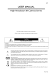
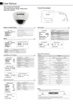
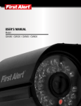
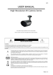
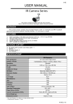
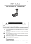
350Z
USER MANUAL
IR Camera Series
Please read the instructions thoroughly before using the product.
CAUTION
RISK OF ELECTRIC SHOCK
CAUTION:
To reduce the risk of electric shock, do not expose this apparatus to rain or moisture.
Only operate this apparatus from the type of power source indicated on the label.
The company shall not be liable for any damages arising out of any improper use, even if we have been advised of the possibility of such
damages.
The lightning flash with arrowhead symbol, within an equilateral triangle, is intended to alert the user to the presence
of uninsulated “dangerous voltage” within the product’s enclosure that may be of sufficient magnitude to constitute a
risk of electric shock to persons.
This exclamation point within an equilateral triangle is intended to alert the user to the presence of important
operating and maintenance (servicing) instructions in the literature accompanying the appliance.
ROHS Announcement
All lead-free products offered by the company comply with the requirements of the European law on the Restriction of
Hazardous Substances (RoHS) directive, which means our manufacture processes and products are strictly
“lead-free” and without the hazardous substances cited in the directive.
The crossed-out wheeled bin mark symbolizes that within the European Union the product must be collected
separately at the product end-of-life. This applies to your product and any peripherals marked with this symbol. Do not
dispose of these products as unsorted municipal waste.
CE Mark
This apparatus is manufactured to comply with the radio interference.
The company does not warrant that this manual will be uninterrupted or error-free. We reserve the right to revise or
remove any content in this manual at any time.
K149D_149H_V1.1
FEATURES
1.
High resolution of 520 TV Lines (Model 2 Only)
2.
High sensitivity in the dark environment, 0.1 Lux / F2.0, 0 Lux (IR ON)
4.
IR distance: up to 40 meters with 56 IR LEDs
3.
5.
Day and night features for 24-hour surveillance
IP67, suitable for outdoor use
PACKAGE CONTENT
IR camera * 1
Bracket * 1
User Manual * 1
SPECIFICATIONS*
MODEL
Pick-up Element
Number of Pixels
Model 1
Model 2
1/3" Color CCD
1/3" H.R. Color CCD
512(H) x 492(V) <NTSC> /
768(H) x 494(V) <NTSC> /
512(H) x 582(V) <PAL>
752(H) x 582(V)) <PAL>
Standard
520TVL
Resolution
Min. Illumination
IR LED
IR Effective Range
S/N Ratio
Electronic Shutter
Lens
Lens Angle
0.1 Lux / F2.0, 0 Lux (IR ON)
56 units
Up to 40 meters
More than 48dB (AGC off)
1/60 (1/50) to 1/100,000 sec.
f6.0mm / F2.0
54°
White Balance
ATW
AGC
Auto
IRIS Mode
AES
IP Rating
IP67
Video Output
Operating Temperature
Power Source (±10%)
Current Consumption (±10%)
Dimensions (mm)**
* The specifications are subject to change without notice.
** Dimensional Tolerance: ± 5mm
1.0Vp-p composite, 75Ω
-20℃~40℃
DC12V
70mA (IR OFF), 590mA (IR ON)
115.6(Ø) × 216.4(H)
INSTALLATION
1. Find the bracket and bracket base from the sales package, and assemble them. (Figure 1)
2. For hiding the video and power cables behind the wall, drill a hole on the wall where you want to install the
camera for the cables to go through.
For arranging the video and power cables along the wall, please skip to Step 3.
3. Attach the bracket base to the wall where you want to install the camera with three screws.
4. Find the joint lock of the bracket from the sales package, and fasten it to your camera. (Figure 2)
5. Screw the camera with the joint lock to the bracket.
6. For hiding the video and power cables behind the wall, pass the video and power cables from the hole on the
bracket as indicated in Figure 3.
For arranging the video and power cables along the wall, please skip to Step 7.
7. Fasten the camera with the joint lock to the bracket.
8. Adjust the viewing angle of the camera, and fasten the joint lock to fix the angle.
Assemble
Figure 1
Figure 2
Figure 3
Figure 4
CONNECTION
1. DC12V Input Terminal
Connect the power terminal of the camera to a DC 12V regulated power supply.
NOTE: Please use the correct power adaptor, DC12V (regulated), to operate this unit. The power
tolerance of this unit is DC12V ± 10%. Over maximum DC 12V power input will damage this unit.
2. Video Output Connector (VIDEO OUT)
Connect the camera video output and the monitor video input with 75Ω coaxial cable.
NOTE: To ensure the camera has sufficient protection against moisture, an extra waterproof measure,
such as by using an insulating tape, must be used to cover the power and video connectors after
connection.