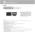
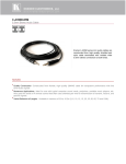
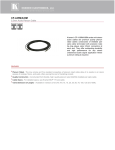
1
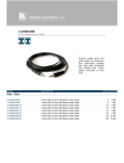
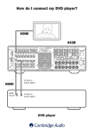
K R A ME R E LE CT R O N IC S L T D . USER MANUAL MODELS: 650T DVI–Coax Transmitter 650R Coax–DVI Receiver P/N: 2900-000536 Rev 7 Contents 1 Introduction 1 2 2.1 Getting Started Achieving the Best Performance 2 2 3 3.1 3.2 4 4.1 4.2 Overview 650T DVI-Coax Transmitter 650R Coax-DVI Receiver Your 650T/650R DVI/Coax Transmitter/Receiver Your 650T DVI-Coax Transmitter Your 650R Coax-DVI Receiver 3 3 3 5 5 6 5 Connecting the 640T/640R 7 6 Technical Specifications 9 Figures Figure 1: 640T/640R HDMI/Coax Transmitter/Receiver Figure 2: 650R Coax-DVI Receiver Figure 3: DVI-to-Coax Transmitter and Receiver System U 5 6 8 U U U U 640T/640R – Contents U i 1 Introduction Welcome to Kramer Electronics! Since 1981, Kramer Electronics has been providing a world of unique, creative, and affordable solutions to the vast range of problems that confront the video, audio, presentation, and broadcasting professional on a daily basis. In recent years, we have redesigned and upgraded most of our line, making the best even better! Our 1,000-plus different models now appear in 11 groups that are clearly defined by function: GROUP 1: Distribution Amplifiers; GROUP 2: Switchers and Matrix Switchers; GROUP 3: Control Systems; GROUP 4: Format/Standards Converters; GROUP 5: Range Extenders and Repeaters; GROUP 6: Specialty AV Products; GROUP 7: Scan Converters and Scalers; GROUP 8: Cables and Connectors; GROUP 9: Room Connectivity; GROUP 10: Accessories and Rack Adapters and GROUP 11: Sierra Products. Thank you for purchasing the Kramer DigiTOOLS® 650T DVI-Coax Transmitter and/or Kramer DigiTOOLS®650R Coax-DVI Receiver, which are ideal for: • Boardroom and projection applications • Long-range multimedia extension for schools, hospitals, security, and stores • Upgrading a legacy analog installation to a digital installation 640T/640R - Introduction 1 2 Getting Started We recommend that you: • Unpack the equipment carefully and save the original box and packaging materials for possible future shipment • Review the contents of this user manual • Use Kramer high performance high resolution cables i 2.1 Go to http://www.kramerelectronics.com to check for up-to-date user manuals, application programs, and to check if firmware upgrades are available (where appropriate). Achieving the Best Performance To achieve the best performance: • Use only good quality connection cables to avoid interference, deterioration in signal quality due to poor matching, and elevated noise levels (often associated with low quality cables) • Avoid interference from neighboring electrical appliances that may adversely influence signal quality • Position your Kramer 640T/640R away from moisture, excessive sunlight and dust ! 2 Caution: No operator serviceable parts inside the unit Warning: Use only the Kramer Electronics input power wall adapter that is provided with the unit Warning: Disconnect the power and unplug the unit from the wall before installing 640T/640R - Getting Started 3 Overview This section describes the: 3.1 • 650T DVI-Coax Transmitter, see Section 3.1 • 650R Coax-DVI Receiver, see Section 3.2 650T DVI-Coax Transmitter The Kramer DigiTOOLS® 650T is an DVI-coax transmitter that receives an DVI signal, codes it, and transmits red, green, blue, clock and data signals, as well as power, infrared and RS-232 control signals over coax cable to the 650R receiver. Compatible with a Kramer transmitter and via a Kramer external remote IR receiver: C-A35M/IRR or C-A35M/IRE or C-A35M/2IRE. The 650T features: • A maximum data rate of 6.75Gbps (2.25Gbps per graphic channel) • Digital signal transmission without compression or conversion • HDTV compatibility and HDCP compliance • Bi-directional IR (Compatible with a Kramer transmitter and via a Kramer external remote IR receiver: C-A35M/IRR or C-A35M/IRE or C-A35M/2IRE) and RS-232 interfaces IR and RS-232 data is available only when using a 5-plug coax cable and the power coax line is connected. 3.2 • Power feeding to the 650R • Plug and Play installation with no adjustments 650R Coax-DVI Receiver The Kramer DigiTOOLS® 650R is a coax-DVI receiver that receives a coded coax signal transmitted by the 650T. It decodes the R-G-B, clock and data components and converts them to an DVI output. 640T/640R - Overview 3 The 650R features: • A maximum data rate of 6.75Gbps (2.25Gbps per graphic channel) • HDTV compatibility and HDCP compliance • Bi-directional IR (Compatible with a Kramer transmitter and via a Kramer external remote IR receiver: C-A35M/IRR or C-A35M/IRE or C-A35M/2IRE) and RS-232 interfaces IR and RS-232 data is available only when using a 5-plug coax cable and the power coax line is connected. 4 • Power feeding to the 650T • Plug and Play installation with no adjustments 640T/640R - Overview 4 Your 650T/650R DVI/Coax Transmitter/Receiver This section defines the 650T DVI-Coax Transmitter (see Section 4.1) and the 650R Coax-DVI Receiver (see Section 4.2) 4.1 Your 650T DVI-Coax Transmitter Figure 1 defines the 650T: Figure 1: 640T/640R HDMI/Coax Transmitter/Receiver # Feature Function 1 RED Output BNC Connector Transmits the red signal to the 650R 2 GREEN Output BNC Connector Transmits the green signal to the 650R 3 BLUE Output BNC Connector Transmits the blue signal to the 650R 4 CLK Output BNC Connector Transmits the clock signal to the 650R 5 PWR Output BNC Connector Transmits power and the IR signal to the 650R 6 12V DC +12V DC connector for powering the unit 7 IR Connector Connects to an IR sensor or transmitter Compatible with a Kramer transmitter and via a Kramer external remote IR receiver: C-A35M/IRR or C-A35M/IRE or C-A35M/2IRE 8 IN / OUT LED The IN LED Illuminates when an input source is connected. The OUT LED illuminates when an output acceptor is connected 9 RS-232 9-pin D-sub Connector Connects to an RS-232 computer source 10 DVI IN Connector Connects to a DVI source 11 ON LED Illuminates when receiving power 640T/640R - Your 650T/650R DVI/Coax Transmitter/Receiver 5 4.2 Your 650R Coax-DVI Receiver Figure 2 defines the 650R: Figure 2: 650R Coax-DVI Receiver # Feature Function 1 RED Input BNC Connector Receives the red signal from the 650T 2 GREEN Input BNC Connector Receives the green signal from the 650T 3 BLUE Input BNC Connector Receives the blue signal from the 650T 4 CLK Input BNC Connector Receives the clock signal from the 650T 5 PWR Input BNC Connector Receives power and the IR signal from the 650T 6 12V DC +12V DC connector for powering the unit 7 IR Connector Connects to an IR sensor or transmitter Compatible with a Kramer transmitter and via a Kramer external remote IR receiver: C-A35M/IRR or C-A35M/IRE or C-A35M/2IRE 6 8 IN / OUT LED The IN LED Illuminates when an input source is connected. The OUT LED illuminates when an output acceptor is connected 9 RS-232 9-pin D-sub Connector Connects to an RS-232 computer source 10 DVI OUT Connector Connects to a DVI acceptor 11 ON LED Illuminates when receiving power 640T/640R - Your 650T/650R DVI/Coax Transmitter/Receiver 5 Connecting the 640T/640R You can use the 650T DVI-Coax Transmitter and the 650R Coax-DVI Receiver to configure an DVI-to-Coax Transmitter and Receiver system (see Figure 3). i Always switch off the power to each device before connecting it to your 640T/640R. After connecting your 640T/640R, connect its power and then switch on the power to each device. To connect the DVI-to-Coax Transmitter and Receiver system as shown in the example in Figure 3, do the following: 1. Connect an DVI source, for example, the DVI output from a Blu-ray DVD player, to the 650T DVI IN connector. 2. Connect the 650R DVI OUT connector to the DVI acceptor, for example, a projector. 3. If using a 4-plug coax cable or 4 coax cables: Connect the 650T red, green, blue, and clock BNC connectors to the 650R red, green, blue and, clock BNC connectors Connect 12V DC power supplies to both the 650T and the 650R (not shown in Figure 3). The remote power and IR remote control functions are not available 4. If using a 5-plug coax cable or 5 coax cables: Connect the 650T red, green, blue, clock, and power BNC connectors to the 650R red, green, blue, clock, and power BNC connectors Connect one 12V DC power supply to either the 650T or the 650R (not shown in Figure 3). Power and the IR remote control function are transmitted over the power coax connection to the second device Note: All coax cables must be the same length. There can be no more than 6 inches (15cm) difference in length between any of the cables. 5. Connect the power supply(s) to the mains electricity. After all connections are made and the units are powered ON, the system operates. 640T/640R - Connecting the 640T/640R 7 Figure 3: DVI-to-Coax Transmitter and Receiver System 8 640T/640R - Connecting the 640T/640R 6 Technical Specifications INPUTS: 1 DVI connector 5 BNC connectors OUTPUTS: 5 BNC connectors 1 DVI connector PORT: IR on a 3.5mm mini jack, RS-232 on a 9-pin D-sub connector MAX. DATA RATE: Supports up to 6.75Gbps (2.25Gbps per graphic channel) STANDARDS COMPLIANCE: HDCP POWER SOURCE: 12V DC, 270mA (650T) 12V DC 450mA (650T / 650R pair when powered from 650T via Power Connect with 60m cable) OPERATING TEMPERATURE: 0° to +55°C (32° to 131°F) STORAGE TEMPERATURE: -45° to +72°C (-49° to 162°F) HUMIDITY: 12V DC, 160mA (650R) 12V DC 590mA (650T / 650R pair when powered from 650R via Power Connect with 60m cable) 10% to 90%, RHL non-condensing DIMENSIONS: 12.0cm x 7.0cm x 2.4cm (4.7" x 2.8" x 1.0"), W, D, H WEIGHT: 0.3kg (0.7lbs) approx. ACCESSORIES: Power supply OPTIONS: Kramer external remote IR receiver C-A35M/IRR or C-A35M/IRE or C-A35M/2IRE Specifications are subject to change without notice at http://www.kramerelectronics.com 650T/650R Range Chart Cable Type Max Range BC-5 (28 AWG) 50m BC-5 (26 AWG) 60m RG-59 115m RG-6 150m 640T/640R - Technical Specifications 9 10 For the latest information on our products and a list of Kramer distributors, visit our Web site where updates to this user manual may be found. We welcome your questions, comments, and feedback. Web site: www.kramerelectronics.com E-mail: [email protected] ! SAFETY WARNING Disconnect the unit from the power supply before opening and servicing