1
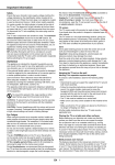
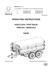
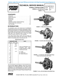
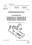
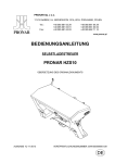
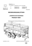
PRONAR Sp. z o.o. 17-210 NAREW, UL. MICKIEWICZA 101A, PODLASKIE PROVINCE tel.: fax: +48 085 681 63 29 +48 085 681 63 81 +48 085 681 63 83 +48 085 681 64 29 +48 085 681 63 82 +48 085 682 71 10 www.pronar.pl OPERATOR'S MANUAL AGRICULTURAL TRAILER PRONAR T025 TRANSLATION OF THE ORIGINAL INSTRUCTIONS ISSUE 3B-01-2010 PUBLICATION NO 150N-00000000-UM GB INTRODUCTION Information contained herein is current at date of publication. As a result of improvements, some numerical values and illustrations contained in this publication may not correspond to the factual specification of the machine supplied to the user. The manufacturer reserves the right to introduce design changes in machines produced that facilitate operation and improve the quality of their work, without making minor amendments to this Operator's Manual. This Operator's Manual is an integral part of the machine's documentation. Before using the machine, the user must carefully read this Operator's Manual and observe all recommendations. This guarantees safe operation and ensures malfunction free work of the machine. The machine is designed to meet obligatory standards, documents and legal regulations currently in force. The Operator's Manual describes the basic principles of safety in use and operation of the Pronar T025 agricultural trailer. If the information contained in the Operator's Manual needs clarification then the user should refer for assistance to the sale point where the machine was purchased or to the Manufacturer. Manufacturer’s address: PRONAR Sp. z o.o. ul. Mickiewicza 101A 17-210 Narew Telephone numbers +48 085 681 63 29 +48 085 681 64 29 +48 085 681 63 81 +48 085 681 63 82 Information, description of threats and precautions as well as recommendations and orders connected with safety of use, in contents of the instruction, are distinguished with the sign: or preceded with the word „ATTENTION". Non-compliance with recommendations described in the manual creates danger for life and health of operators or strangers. Particularly important information and recommendations the observance of which is utterly necessary are distinguished in the text with this sign: or preceded with the word „CAUTION”. Non-compliance with described recommendations is imminent damage of the machine due to improper service, adjustment or use. In order to point out the necessity of performing periodic technical review of the machine, the content of particular paragraphs has been marked with the clock sign: TABLE OF CONTENTS 1. BASIC INFORMATION 1.1 IDENTIFICATION........................................................................................... 1.2 INTENDED USE ............................................................................................ 1.3 ACCESSORIES ............................................................................................. 1.5 WARRANTY TERMS & CONDITIONS .......................................................... 1.5 TRANSPORTATION ...................................................................................... 1.6 ENVIRONMENTAL HAZARDS ...................................................................... 1.8 DISPOSAL ..................................................................................................... 1.9 2. USER’S SAFETY 2.1 BASIC SAFETY RULES ................................................................................ 2.2 RULES OF USING PUBLIC ROADS ............................................................. 2.6 RESIDUAL RISK DESCRIPTION .................................................................. 2.7 WARNING & INFORMATION LABELS.......................................................... 2.8 3. DESIGN & OPERATION PRINCIPLE 3.1 TECHNICAL CHARACTERISTICS ................................................................ 3.2 TRAILER DESIGN ......................................................................................... 3.3 MAIN BRAKE................................................................................................. 3.5 PARKING BRAKE.......................................................................................... 3.8 ELECTRICAL INSTALLATION, WARNING ELEMENTS ............................... 3.9 4. OPERATION RULES 4.1 PREPARATIONS BEFORE FIRST START-UP ............................................. 4.2 TECHNICAL CONDITION CONTROL ........................................................... 4.2 ACCOUPLING WITH TRACTOR ................................................................... 4.4 LOADING, TRANSPORTATION & UNLOADING .......................................... 4.7 DISCONNECTING FROM TRACTOR ........................................................... 4.8 TIRES REPAIR & REPLACING WORKS....................................................... 4.8 5 TECHNICAL SERVICE 5.1 TRACTION AXLES BEARING CONTROL AND REGULATION.................... 5.2 ADJUSTING MAIN BRAKE............................................................................ 5.3 ADJUSTING PARKING BRAKE.....................................................................5.5 PNEUMATIC BRAKING SYSTEM MAINTENANCE ......................................5.6 HYDRAULIC BRAKING SYSTEM MAINTENANCE.......................................5.7 LUBRICATION ...............................................................................................5.9 SPRINGS SYSTEM MAINTENANCE ............................................................5.10 STORAGE......................................................................................................5.10 ADJUSTING DRAUGHT BAR TO TRACTOR HOOK-TYPE COUPLING ......5.12 SCREW JOINTS TORQUE............................................................................5.12 TROUBLESHOOTING ...................................................................................5.14 LIST OF BULBS .............................................................................................5.14 CHAPTER 1 BASIC INFORMATION IDENTIFICATION INTENDED USE ACCESSORIES WARRANTY TERMS & CONDITIONS TRANSPORTATION ENVIRONMENTAL HAZARDS DISPOSAL 1.1 1.1 IDENTIFICATION PRONAR A B F C G D H E I J K 1 o. z .o 0a Sp. 17-21Nw nar c a 01A, 2 6 9 Proickiewiz1 ) 6813 ar pl 0 5 ul. M (8 ar /fax: pron. re kg kg tel. il: pron@ a e-m 01 Masa w³.ca³k. 000 kg 5 Do.p m. XX71X T02 kN 250 / yp SymbolTod. SZB0£adoown œæ cz. kN c. za Rok pr. kN Dop. obbc. osi Nr fba rhom. Dop. o Nrwœ . SZB0250XX71X00001 1 2 FIGURE 1.1A IDENTIFICATION OF BALE TRANSPORT TRAILER (1) data plate, (2) serial number Bale transport trailer has a data plate placed on the front frame beam. The serial number is imprinted both on the data plate and on the left side of the front frame beam within the silverpainted rectangular field. When purchasing it is recommended to make sure that the numbers imprinted on the machine by the manufacturer and the numbers entered in the WARRANTY CARD, selling documents and the USER MANUAL are identical. 1.2 Serial number of the traction axis and their type are imprinted on the data plate installed on the traction axle beam. The meaning of the individual fields found on the data plate are presented in the table below: TABLE 1.1 Markings on data plate ITEM MARKING A General description and purpose B Symbol /Type C Year of manufacture D Seventeen digit serial number (VIN) E Official certificate number F Tare weight G Maximum gross weight H Carrying capacity I Maximum hitch load (not applicable) J Permissible front axle load K Permissible rear axle load 1.2 INTENDED USE Bale transport trailer is used for transporting agricultural products and commodities prepared in form of bales or pressed blocks within a farm area and on public roads. The trailer is also intended for transporting agricultural products and commodities on pallets. TABLE 1.1 RECOMMENDED PALLET TYPE PALLET NAME – TYPE Euro pallet – standard Euro pallet – 1/2 LENGHT WIDTH HEIGHT [mm] [mm] [mm] 1 200 800 144 800 600 144 1.3 LENGHT WIDTH HEIGHT [mm] [mm] [mm] Euro pallet – extended 1 200 1 200 144 ISO Pallet 1 200 1 000 144 PALLET NAME – TYPE Braking, signaling and lighting systems are compliant with traffic regulations. Allowable speed on public roads of the trailer in Poland is 30 km/h (according to the Act of 20 June, 1997 „Road Traffic Law”). In countries where the trailer is going to be operated, the users must comply with the local road traffic regulations. The speed of the trailer cannot exceed the constructional speed which is 40 km/h. WARNING The bale transport trailer cannot be operated against its intended use, to transport the following in particular: • animals & people • any materials other than those specified in the User Manual Traction system (axles, springs, wheels and tires), is compliant with the requirements for agricultural machines. Fulfilling these requirements is conditioned by proper operation and observing the instructions included in this User Manual. Bale trailer can be operated together with tractors equipped with 12V lighting electrical installation with seven pole socket and upper transport hook. Depending on the braking system version, agricultural tractor must be equipped with one of the following system types: • pneumatic single brake cable system, • pneumatic double break cable system, • hydraulic breaking system. ATTENTION Hydraulic braking system uses HL32 hydraulic oil. 1.4 1.3 ACCESSORIES The following comes complete with the bale transport trailer: • USER MANUAL, • WARRANTY CARD, • electrical installation connection cable, • chocks. On demand of the client, the Manufacturer can equip the bale trailer with the following additional elements: • “Low Speed Vehicle” plate, • warning triangle. 1.4 WARRANTY TERMS & CONDITIONS PRONAR Sp. z o.o., Narew guarantees the reliable operation of the machine when it is used according to its intended purpose as described in the OPERATOR'S MANUAL. The repair period is specified in the WARRANTY BOOK. The guarantee does not apply to those parts and sub-assemblies of the machine, which are subject to wear in normal usage conditions, regardless of the warranty period. Consumables include the following parts/sub-assemblies: • drawbar hitching eye, • pneumatic system connector filters, • tyres, • brake shoes, • bulbs and LED lamps, • seals, • bearings. The warranty service only applies to such cases as: mechanical damage, which is not the user's fault, factory defects of parts, etc. 1.5 In the event of damage arising from: • mechanical damage which is the user's fault, caused by road accidents, • by inappropriate use, adjustment or maintenance, use of the trailer for purposes other than those for which it is intended, • use of damaged machine, • repairs carried out by unauthorised persons, improperly carried out repairs, • making unauthorised alterations to machine design, the user will lose the right to warranty service. TIP Demand that the seller carefully and precisely fills out the Warranty Book and guarantee repair coupons. A missing date of purchase or sale point stamp, may make the user ineligible for any warranty repair or refund. The user is obliged to report immediately on noticing any wear in the paint coating or traces of corrosion, and to have the faults rectified whether they are covered by the guarantee or not. Detailed guarantee regulations are contained in the WARRANTY BOOK attached to each machine. Modification of the trailer without the written consent of the Manufacturer is forbidden. In particular, do NOT weld, drill holes in, cut or keep the main structural elements of the machine, which have a direct impact on the machine operation safety. 1.5 TRANSPORTATION Bale trailer is ready for selling as completely assembled machine and does not require packaging. The only thing needs to be packed is the operation & maintenance manual and elements of additional equipment, if ordered. Machine delivery to the customer is possible with the use of a vehicle. After coupling, it can be also transported with the use of a tractor. When loading and unloading the trailer the general work safety rules must be observed. Workers operating the unloading equipment must have relevant qualifications for such equipment operation. 1.6 WARNING When transporting the trailer with the use of a tractor, the driver should get acquainted with this User Manual and observe the instructions therein. When transporting the trailer on a vehicle platform, the trailer is secured according to the required safety regulations. The driver of a vehicle transporting the bale trailer should take special care. It is so because the centre of gravity of the vehicle transporting the trailer is shifted upwards. Bale trailer must be properly secured on the transportation vehicle platform with the use of fastening belts or chains equipped with the tensioning mechanism. Fastening elements must have valid safety attestation. Chocks or other elements with no sharp edges must be placed against the bale trailer wheels. Chocks must be fastened to the transportation vehicle platform. 1 1 FIGURE 1.2A ARRANGEMENT OF TRANSPORTATION EARS (1) transportation ear When performing the unloading works special attention must be paid so that the both equipment elements of the trailer and paint coat are not damaged. Belts and/or chains must be fastened to the transportation eyes (1), the arrangement of which on the left side of the trailer is shown on the Fig. (1.2A), or to other elements of the trailer (side members, 1.7 crosspieces, etc.), making sure that the fastening is secure enough to guarantee transportation safety. 1.6 ENVIRONMENTAL HAZARDS A hydraulic oil leak constitutes a direct threat to the natural environment owing to its limited biodegradability. Because of the low solubility of oil in water, it is not highly toxic to living organisms. An oil leak into water reservoirs may however lead to a reduction of the oxygen content. While carrying out maintenance and repair work which involves the risk of an oil leak, this work should take place on an oil resistant floor or surface. In the event of oil leaking into the environment, first of all contain the source of the leak, and then collect the leaked oil using available means. Remaining oil should be collected using sorbents, or by mixing the oil with sand, sawdust or other absorbent materials. The oil pollution, once gathered up, should be kept in a sealed, marked, hydrocarbon resistant container. The container should be kept away from heat sources, flammable materials and food. DANGER Used hydraulic oil or gathered remains mixed with absorbent material should be stored in a precisely marked container. Do not use food packaging for this purpose. Oil which has been used up or is unsuitable for further use owing to a loss of its properties should be stored in its original packaging in the conditions described above. Waste oil should be taken to the appropriate facility dealing with the re-use of this type of waste. Waste code: 13 01 10. Detailed information concerning hydraulic oil may be found on the product's Material Safety Data Sheet. TIP The hydraulic system of the trailer is filled with L-HL32 Lotos hydraulic oil. IMPORTANT! Waste oil should only be taken to the appropriate facility dealing with the re-use of this type of waste. Do NOT throw or pour oil into sewerage or water tanks. 1.8 1.7 DISPOSAL In the event of decision by the user to withdraw the trailer from use, comply with the regulations in force in the given country concerning withdrawal from use and recycling of machines withdrawn from use. Before commencing dismantling, totally remove the oil from the hydraulic system and reduce air pressure completely in the pneumatic brake system (e.g. using air tank drain valve). DANGER During dismantling personal protection equipment shall be used i.e. protective clothing, boots, gloves and protective goggles etc. Avoid contact of skin with oil. Do not allow used hydraulic oil to spill. When spare parts are changed, worn out or damaged parts that cannot be reclaimed should be taken to a collection point for recyclable raw materials. Hydraulic oil should be taken to the appropriate facility dealing with the re-use of this type of waste. 1.9 1.10 CHAPTER 2 USER’S SAFETY BASIC SAFETY RULES RULES OF USING PUBLIC ROADS RESIDUAL RISK DESCRIPTION WARNING & INFORMATION LABELS 2.1 2.1 BASIC SAFETY RULES • Before proceeding with the operation of the trailer, the user should carefully get acquainted with these safety rules. When operating the trailer the user must observe all the safety instructions. Operation and maintenance of the trailer must be performed only by the persons qualified to operate agricultural tractors and machines. • If the information included in the User Manual is not clear it is recommended for a user to contact the dealer authorized by the Manufacturer of the trailer providing technical services or directly with the Manufacturer. • Improper or unintended use of the trailer as well as the improper maintenance and inobservance of all the instructions provided in this Charter pose a danger to a trailer user. • As a residual risk exists the observing of safety rules and proper operation of the trailer should be the basic principle when using the machine. • It is forbidden for persons unqualified for operating agricultural tractors to operate the bale trailer, children and persons under the influence of alcohol including. • Non-observance of safety rules poses a threat to health of the machine operators and any outsiders. • It is forbidden to operate the trailer against its intended use. A person operating the machine against its intended use bears the responsibility for and resultant consequences. Using the trailer for other purposes than those specified by the manufacturer (see Chapter (1.2)) is considered as unintended and may be the reason for the warranty terms & conditions to be revoked. • Any modifications to the bale trailer introduced without the explicit consent of the PRONAR Narew releases the company form any liability concerning the modificationrelated defects or health impairment. • Climbing up and down the trailer is admissible only when the machine is immobilized and with a tractor engine switched off. Safe and high enough ladders and platforms must be used when climbing and leaving the trailer. • In case of the braking system failure it is forbidden to operate the trailer until the defect is repaired. 2.2 • Bale trailer disconnected from a tractor must be immobilized with parking brake. If a trailer is parked on a sloped or elevated area it must be additionally secured with the use of chocks or other elements without sharp edges placed against the wheels. • It is forbidden to transport people or animals on the platform of the trailer. • It is forbidden to connect the trailer to a tractor in case different hydraulic oil grades are used in both machines (applies to the trailer equipped with hydraulic braking system) – consult with the table (5.4). • It is forbidden to operate defective trailer. • It is forbidden to exceed the allowable load capacity of the trailer. The exceeded load capacity may result in the trailer damage, loss of stability when pulled by a tractor, loss of transported products and causing danger when the trailer is operated or pulled. • The technical condition of the trailer and tractor’s coupling system and connection elements of braking and electrical system must be inspected each time before it is going to be used. • Special care must be taken when connecting or disconnecting the trailer to a tractor. • When connecting the trailer to a tractor no person can stay between the trailer and a tractor. • When connecting the trailer to a tractor only the upper transport hook must be used. Inspect the safeguard mechanism. • If the bale trailer is equipped with coupling system for connecting the second trailer, the extendable frame must be pulled in. • Transported products must be placed evenly on the trailer. • Keep safe distance when loading and unloading products from the trailer. The outsiders must stay away from the working area. • Transported products must be protected from being displaced with the use of belts, chains, tapes or other fastening elements. The elements must be equipped with tensioning mechanism or have relevant safety attestations. • Air tank or hydraulic braking system are under high pressure when the trailer is operated. 2.3 • Frequently control the condition of braking system. Any braking system oil spills or leakage must be eliminated. • Control the connection and pneumatic and hydraulic cables technical conditions on a daily basis. • When connecting hydraulic cables to a tractor, make sure that the tractor hydraulic braking system is not under pressure. • Before any pneumatic or hydraulic braking system repair or maintenance works the air an oil pressure must by reduced. • When injured by the compressed hydraulic oil, immediately consult with a doctor. Hydraulic oil can penetrate the skin and cause infection. • Use only the hydraulic oil grade recommended by the Manufacturer. Never mix two different oil grades. • The used hydraulic oil must be utilized. • It is forbidden for a user to repair the control valve, braking actuator or braking force regulator. These elements must be either replaced or repaired by qualified workers. • When replacing tires the trailer must be secured from rolling through the use of chocks or other blocking elements without sharp edges. Wheel removing may be performed only when the bale trailer is empty. • Paint coat must be removed before proceeding with welding works. Vapors of burning paint are harmful for both people and animals. Welding works must be performed in a well-ventilated and illuminated room. • Special attention must be paid to flammable or fusible elements when performing welding works (pneumatic and hydraulic braking system elements, elements made of rubber or plastic). If there is a risk such elements may be damaged or burned they must be removed. • Wheel or tire replacing works must be performed by trained and qualified persons. The works must be performed with the use of relevant tools. • Each time a wheel is installed it must be checked if the lug nuts are properly tightened. Such control must be performed after the first use of the trailer, first use of the loaded 2.4 trailer, after first 1000 km and than every 6 months. Such control must be repeated each time a wheel was removed from a traction axle. • Tire pressure must be regularly controlled. • In case any failure is detected the trailer cannot be operated until the failure is repaired. It is forbidden to use the trailer when defected. • Use protective gloves, tightly fitting clothes and proper tools when operating the trailer. • Maintenance and repair works must be performed in accordance with the general work safety rules. When cut, the wound must be immediately rinsed and disinfected. In case of serious injuries consult with a doctor. • Repair, maintenance and cleaning works must be performed with a tractor engine switched off and keys removed from the ignition switch. • Screw connections must be regularly inspected. • Before proceeding with welding or electrical installation works, the trailer must be disconnected from power supply. • In the warranty period any repairs can be performed only by the service workers authorized by the Manufacturer. • In case it is necessary to replace individual elements, only original ones can be used. This requirement inobservance may create danger to health or life of outsiders and machine operators or to contribute to the damage of the machine itself, thus constituting the basis for revoking the warranty terms & conditions. • When performing works requiring lifting the trailer, proper hydraulic or mechanical and attested jacks must be used. After lifting, it is required to use stabile support as additional protection. It is forbidden to perform any works under the trailer when it is lifted only with the use of a jack. • It is forbidden to support the trailer with the use of fragile elements such as bricks, breezeblocks, concrete blocks). • After lubricating, the excess amount of oil must be removed. • Properly selected tools, tightly fitting clothes and protective gloves must be used when operating, maintaining or clearing the trailer. 2.5 2.2 RULES OF USING PUBLIC ROADS • When using the trailer on public roads, it is necessary to place a “Slow Vehicle” plate on the rear side of the trailer. • Observe traffic regulations. • Exceeding the allowable load capacity of the trailer may result in its damage and pose a threat to the safety of other road users. • Do not exceed the allowable traveling speed. Adjust the speed to road conditions. • It is forbidden to leave the bale trailer without proper protection. The protection consists in applying the handbrake and, if required, placing chocks against the trailer wheels. • The trailer must be equipped with warning or type approved triangle when using the trailer on public roads. • It is forbidden to use the trailer on public roads with the frame being extended. 1 FIGURE 2.1A TRIANGLE PLACING (1) Low Speed Vehicle plate 2.6 2.3 RESIDUAL RISK DESCRIPTION Every effort has been made by Pronar Sp. z o. o. in Narew to eliminate any accidents. However, there is still a residual risk which may result in an accident. The risk mainly concerns the following: • using the trailer for purposes other than those specified by the Manufacturer, • staying between a tractor and the trailer when a tractor engine is on and at the time the trailer is connecting to a tractor, • operating the trailer by persons under the influence of alcohol or drugs, • operating the trailer by unqualified persons, • staying on the trailer platform when it is operated, • careless performance of clearing, maintenance, repair works and technical inspection of the bale trailer. Residual risk can be reduced to minimum when observing the following instructions: • operate the trailer in an unrushed and careful manner, • observe the information included in the User Manual, • keep safe distance form dangerous and access-forbidden areas, • do not stay on the trailer platform when it is operated, • let qualified workers perform repair and maintenance works, • use properly fitted protective clothes, • protect the trailer form being accessed by unqualified persons, children in particular. 2.4 WARNING & INFORMARION LABELS Bale trailer is marked with warning and information labels listed in the Table (2.1). The arrangement of the labels is show on the Fig. (2.2A). The user of the machine is obliged to make sure that the quality of the warning & information labels is legible throughout the whole period of the trailer operation. In case the quality deteriorates the labels must be replaced. User can purchase the labels from the Manufacturer or the dealer. New assemblies replaced during repair works must be remarked with relevant safety labels. 2.7 TABLE 2.1 WARNING & INFORMATION LABELS NO. SYMBOL INTERPRETATION 1 Become familiar with THE USER MANUAL 2 Switch off the engine and remove keys from the ignition switch before proceeding with maintenance or repair works. 3 Keep safe distance. Possible crushing by the shaft and protective ladder. Regularly control the technical condition of screw connections of traction axis. 50-100 km 4 M18 M20 M22 27 kGm 35 kGm 45 kGm Lubrication to be performed according to instructions included in the User Manual 5 Smarować ! Grease ! Schmieren ! 6 7 350 kPa Tire pressure T025 PRONAR Bale trailer type - air pressure in tire standard equipment, pressure value depends on tire type used. 2.8 6 3 2 1 4 5 7 FIGURE 2.2A LABELS ARRANGEMENT Markings in the Fig. comply with the Table 2.1 „Warning & Information Labels” 2.9 2.10 CHAPTER 3 DESIGN & OPERATION PRINCIPLE TECHNICAL CHARACTERISTICS TRAILER DESIGN MAIN BRAKE PARKING BRAKE ELECTRICAL INSTALLATION, WARNING ELEMENTS 3.1 3.1 TECHNICAL CHARACTERISTICS TABLE 3.1 TRAILER BASIC TECHNICAL DATA CONTENT UNIT OF MEASURE T130 - with rear frame extended mm 9 670 - with rear frame pulled in mm 9 140 Width mm 2 500 Height mm 2 830 - with rear frame extended mm 7 610 - with rear frame pulled in mm 8 140 mm 2 450 Design allowable load capacity kg 9 040 Allowable total weight kg 12 000 Vehicle kerb mass kg 2 960 mm 1 190 Tire size - 500/50-17 Plate wheel size - 16.00 x 17’’ ET=-35 Tire air pressure kPa 350 V 12 Wheel base mm 1 820 Allowable design speed km/h 40 (30) Dimensions Length Dimensions of load platform Load surface length Width Use Parameters Load surface lift Tires Additional Information Electrical installation voltage - standard tire air pressure, air pressure value may differ depending on tires type - Allowable trailer speed on public roads in Poland is 30 km/h (according to the Act of. 20 June 1997, „Traffic regulation act”, art. 20). Local traffic regulations must be observed in countries where the trailer is intended to be operated. The trailer speed cannot exceed the allowable design speed of 40 km/h. 3.2 3.2 TRAILER DESIGN The trailer design has been shown on Fig. (3.1A), (3.2A) and (3.3A). Frame (1) – load platform, is a welded construction made of steel bars. Side members joined with the use of crosspieces are the main bearing elements. The load platform is bounded with ladders (2) and (3) (at its front mounted to the frame (1) and at its back to the extendable frame (4)). Ladders are protected from excessive extension with the use of steel cables (6). On the left side of the frame, the parking brake screw mechanism is welded (from underside). 1 2 FIGURE 3.1A 5 6 4 3 6 BALE TRANSPORT TRAILER (1) frame – load platform, (2) front ladder, (3) rear ladder, (4) extendable frame, (5) parking brake mechanism, (6) protective steel cable Front axle suspension elements are at the front part of the trailer: turn-table (8), turn-table frame (7), parabolic springs (11) shaft (10). 3.3 10 13 14 12 7 8 9 11 FIGURE 3.2A TURN TABLE FRAME WITH FRONT SUSPENSION (7) Turn-table frame, (8) turn- table, (9) traction axle, (10) shaft, (11) parabolic spring, (12) air tank, (13) spring, (14) shaft pivot The shaft is fixed to the turn-table with pivots (14). Shaft connector height can be adjusted through moving the clamp fixing the spring to the shaft. Spring suspension and rear lighting elements are at the back of the frame. Front and rear axis are made of square bar ended with gudgeons where, on the cone bearings, wheel hubs are installed. These are single wheels equipped with jaw brakes operated with mechanical wheel cylinder. 3.4 16 FIGURE 3.3A BALE TRAILER – REAR SIDE VIEW (16) lighting beam 3.3 MAIN BRAKE Depending on version, bale transport trailer is equipped with one of three service brake installation types: • single pipe pneumatic braking system with three position regulator – Fig. (3.4A), • double pipe pneumatic braking system with three position regulator – Fig. (3.5A), • hydraulic braking system – Fig. (3.7A). Main brake is used by a tractor operator through applying the tractor brake pedal. Control valve actuates the trailer brakes with the moment the tractor brake is applied. In case of an unexpected disconnection of the connection pipe in the pneumatic braking system occurs, which is installed between the trailer and a tractor, the control valve will automatically actuate the trailer brake. 3.5 The valve is equipped with the brake release mechanism, which is applied in case the trailer is disconnected from a tractor. After air cable is connected to a tractor, the release mechanism is automatically adjusted to a position allowing normal brake operation. 9 8 7 1 4 6 2 5 3 FIGURE 3.4A SINGLE PIPE PNEUMATIC BRAKE SYSTEM (1) air tank, (2) control valve, (3) braking force regulator, (4) pneumatic actuator, (5) connection, (6) air filter, (7) air tank control connection, (8) actuator control connection, (9) drain valve 3.6 10 9 8 1 4 7 6 2 3 5 FIGURE 3.5A DOUBLE PIPE PNEUMATIC BRAKE SYSTEM (1) air tank, (2) control valve, (3) braking force regulator, (4) pneumatic actuator, (5) red pipe connection, (6) yellow pipe connection, (7) air filter, (8) air tank control connection (9) actuator control connection, (10) drain valve B 2 A C 1 FIGURE 3.6A THREE POSITION BRAKING FORCE REGULATOR (1) braking force regulator, (2) lever, (a) „no load” (b) „half load, (c) „full load” 3.7 Three position braking force regulator – Fig. (3.6A), adjusts braking force in pneumatic braking system depending on regulations made. Switching to required operation mode is performed manually by the trailer operator before the trailer operation with the use of the regulator lever. The regulator has three working positions: „No load”, „Half load”, „Full load”. The most powerful braking force is achieved at the “Full load” position. 1 1 2 FIGURE 3.7A HYDRAULIC BRAKE SYSTEM (1) hydraulic brake actuator, (2) feed pipe connection 3.4 PARKING BRAKE Parking brake is used for making the trailer immobilized when it is not operated. Brake crankshaft mechanism, installed on the left side of the frame, is connected with the use of a steel cable to the levers of traction axis expanders. Through rotating the shaft of the mechanism the steel cable is tensioning. Expanders’ arms are putting pressure on the brake jaws, which makes the axis immobilized. Before the trailer operation, the parking brake must be released - the steel cable must hang loose. 3.8 3.5 ELECTRICAL INSTALLATION, WARNING ELEMENTS 1 2 3 4 5 FIGURE 3.8A ELEMENTS ARRANGEMENT – FRONT SIDE OF THE TRAILER (1) front left head lamp, (2) front right head lamp, (3) front socket, (4) white reflective lamp, (5) orange contour lamp The electrical installation of the bale trailer is intended for the DC 12 V. Electrical connection between the trailer and a tractor must be performed with the use of a proper connection cable supplied together with the machine. The bale trailer is also equipped with reflective elements (lamps) improving the visibility of the trailer when used on public roads. 3.9 4 FIGURE 3.9A 8 1 7 3 3 6 7 2 5 9 ELEMENTS ARRANGEMENT – REAR OF THE TRAILER (1) left rear complex lamp, (2) right rear complex lamp, (3) registration plate illumination lamp, (4) left rear contour lamp, (5) right rear contour lamp, (6) rear socket, (7) warning reflective triangle, (8) “Low Speed Vehicle” plate, (9) orange side contour lamp 3.10 CHAPTER 4 OPERATION RULES PREPARATIONS BEFORE FIRST START-UP TECHNICAL CONDITION CONTROL ACCOUPLING WITH TRACTOR LOADING, TRANSPORTATION & UNLOADING DISCONNECTING FROM TRACTOR TIRES REPAIR & REPLACING WORKS 4.1 4.1 PREPARATIONS BEFORE FIRST START-UP The bale trailer is delivered completely assembled and it is not required to install additional subassemblies. The Manufacturer guarantees that the trailer is full operational, its technical condition has been checked according to control procedures and received operation permit. It is, however, a purchaser’s responsibility to control technical condition of the trailer before the purchase and its first operation. Before connecting to a tractor, the machine operator must control technical condition of the trailer and adjust it to his own needs. The following must be done: • get acquainted with the contents of this Chapter, • immobilize the trailer with the use of a parking brake, • check the condition of the paint coat, make sure that there are not mechanical defects or any corrosion (dents, crimps, punctures or breaks of other accessories), • check tire air pressure and make sure that the lug nuts are properly tightened, • adjust the height of the draught bar to the level of the tractor hook-type coupling. On performing the above procedures the trailer is ready for operation and can be connected to a tractor (see section 4.3). After braking system cables are connected (hydraulic or pneumatic braking system), make sure that the particular systems are working correctly. Make sure that there is not any leakage in the braking system and brake actuator. ATTENTION Non-compliance with the instructions provided in this Chapter or improper performance of the procedures concerning first operation of the trailer may be the reason for the trailer to be damaged. 4.2 TECHNICAL CONDITION CONTROL The following must be done as part of the procedures concerning first operation of the trailer: • control technical condition and air pressure of tires, • tighten lug nut of the wheels and the lock nuts of the shaft, • control technical condition of other screw joints 4.2 • control the trailer lightning & signaling system, • control the technical condition of the braking system, • lubricate elements as specified in the guidelines included in the Chapter „Lubrication points” according to maintenance schedule. WARNING It is forbidden to use a defective trailer. Careless and improper operation of the trailer and noncompliance with the instructions included in this Chapter poses a threat to life and health. Noncompliance with safety rules poses a threat to the machine operator’s health and that of outsiders’. Pneumatic braking system pipes are equipped with connections the protection caps of which are made of tinted plastic. The colors of these elements are the same as the colors of connection sockets installed in a tractor (yellow, red or black). Hydraulic brakes pipe socket must be connected to the hydraulic brake socket installed in a tractor. ATTENTION Before connecting any particular system pipes, a user must get acquainted with the User Manual of a tractor and observe the manufacturer’s instructions. Before proceeding with the operation of the bale trailer, a user must carefully read the instructions in this Chapter. It is forbidden for persons unqualified for driving tractors to operate the trailer, children and persons under the influence of alcohol including. It is forbidden to operate the trailer against its intended use. Technical condition of the trailer must be controlled each time it is going to be operated. Technical condition of the hook, traction & brake system, and illumination signaling must be controlled in particular. The condition of the main brake can be checked only after the trailer is connected to a tractor. If the trailer is not fully operational, it is forbidden to be used until all failures are removed. Before first operation, the height and position of the draught bar must be adjusted to that of a hook-type coupling installed in a tractor. 4.3 4.3 ACCOUPLING WITH TRACTOR Before connecting the trailer to a tractor, make sure the tractor is immobilized with a parking brake. The machine can be connected only to a tractor equipped with an upper hook-type coupling. WARNING When connecting the machine to a tractor nobody can stay in between. The following must be done to perform the connection: • apply parking brake through rotating the crank mechanism (1) in the (A) direction, • set the shaft eye at a proper height (see Chapter 5), • reversing a tractor, connect the shaft eye to the upper hook-type coupling installed in a tractor and make sure it is correctly secured, • connect electrical installation and braking system pipes to a tractor, • release parking brake through rotating the crank mechanism (1) in the (B) direction, • install “Low Speed Vehicle” plate. WARNING Before proceeding with connecting the trailer make sure the coupling systems of the trailer and a tractor, as well as connection elements of the electrical installation and braking system are in good technical condition. Special care must be taken when performing the connection. It is forbidden for anybody to stay between the trailer and a tractor when connecting. Only the upper transport hook must be used when performing the connection. Make sure the connection is well secured. 4.4 B A 1 FIGURE 4.1A HAND BRAKE CRANKSHAFT MECHANISM (1) crankshaft mechanism, (A), (B) turning direction of the mechanism If the trailer is going to be transported on public roads the rear frame must be pulled in. To do this the following procedure must be performed: • apply the trailer parking brake, • remove the bolts (2) securing the extendable frame (1) – consult with the Fig (4.2A), • pull in the frame (1) until it stops in the (B) direction, • reinstall the steel cable fixing elements (3) to new location – holes (4). 4.5 WARNING It is forbidden to transport the trailer on public roads when braking system, signaling and the trailer illumination are defective. When turning, the connection cables must hang loose and must not get entangled in the traction elements of the trailer and a tractor. 3 2 C A B 1 3 4 FIGURE 4.2A PULLING IN THE EXTENDABLE FRAME (1) extendable frame, (2) locking bolts, (3) steel cable, (4) steel cable fixing holes View (C) shows the bolts (2) from the top, after the floor panel is removed. 4.6 4.4 LOADING, TRANSPORT & UNLOADING The trailer can be loaded only when the trailer is connected to a tractor and positioned on a flat ground. Technical condition of steel cables and their fixing to the ladders and the trailer frame must be checked. It is forbidden to load and transport the trailer when the steel cables are defective. The load must be arranged evenly on the platform to ensure proper load distribution on the axis and stability of the trailer. The load cannot extend outside the contour of the load platform. The number of product layers depends on the bale size or pressed blocks as well as the way the load is arranged on the platform and its mass. It is, however, forbidden to exceed the allowable height specified by the traffic regulations and allowable design load capacity. When loading products placed on pallets special attention should be paid to the way they are arranged and distributed on the platform. Pallets must be fixed in such a way that it is impossible for them to be displaced. Pallets must not be piled. The load (pressed blocks, bales or pallets) must be properly protected from being displaced with the use of belts equipped with tensioning mechanism. The belts can be fixed both to the left and right side member, front and rear beam of the extendable frame as well as to the holders welded to the side member. The number of protection mechanisms to be used depends on the way products are loaded, type of load and load size. If the transport is going to take place on a sloped area and/or under unfavorable windy conditions, the height of the load must be adjusted to the transport conditions. ATTENTION It is forbidden to exceed the allowable load capacity. It is forbidden to transport people or animals on the platform. The load must be evenly arranged and distributed on the platform and properly secured. Special attention must be paid to potential danger which is posed by electricity power lines. When transporting the trailer on public roads, the extendable frame must be pulled in. Do not exceed the allowable speed. The traveling speed must be adjusted to the condition existing on a road. 4.7 WARNING Make sure that nobody stays in the close vicinity of the trailer when unloading. Before unloading, the trailer must be positioned on a flat ground, a tractor and the trailer must be immobilized with a parking brake. Forklift truck, conveyor or loaders are recommended for unloading. Keep safe distance when loading and unloading. Outsiders must keep away from the place the loading and unloading works are performed. 4.5 DISCONNECTING FROM TRACTOR The following must be done to disconnect the trailer from a tractor: • stop a tractor, apply parking brake, • apply the trailer parking brake, • disconnect electrical installation and braking system cables form a tractor; protect the ends of the cables from contamination, • disconnect the shaft tow ring from the tractor hook and move a tractor away. WARNING Disconnected bale trailer must be immobilized with a parking brake. If the trailer is parked on a sloped ground it must be protected additionally from rolling down with the use of chocks or other blocking elements without sharp edges placed against the trailer wheels. 4.6 TIRES REPAIR AND REPLACING WORKS • When performing any works concerning tires, the trailer must be protected from rolling through placing chocks or other blocking elements against the wheels. Wheel removing is possible only when the bale trailer is empty. • Tire repair or replacing works can be performed only by specially trained or qualified persons. Such works can be performed only with the use of proper tools. 4.8 • Each time a wheel is installed it is required to make sure the lug nuts are properly tightened. Such control should be performed each time a new wheel has been installed, after first use of the loaded trailer and after first 1000 km and than every 6 months. • Regularly control and maintain proper air pressure according to instructions (especially after longer period the trailer has not been operated). • Tire pressure should also be controlled regularly during the day of an intensive trailer operation. The tire temperature rise, which can increase the pressure even by 1 bar, should be taken into account. At such pressure and temperature increase the load and traveling speed must be lowered. • Never lower the pressure value through venting in case the increase has been caused by the temperature increase. • Valves should be protected with the use of proper nuts to avoid their contamination. • Do not exceed the maximum speed of the trailer. • During the daily operation cycle an hour-brake must be allowed, preferably at noon. • Observe 30-minute breaks required for cooling tires after covering the distance of 75km, or after 150-minute continuous travel, depending what occurs first. • Steer clear of holes in the roads, sudden maneuvers and high speed when turning. 4.9 4.10 CHAPTER 5 TECHNICAL SERVICE TRACTION AXLE BEARING CONTROL AND REGULATION ADJUSTING MAIN BRAKE ADJUSTING PARKING BRAKE PNEUMATIC BRAKING SYSTEM MAINTENANCE HYDRAULIC BRAKING SYSTEM MAINTENANCE LUBRICATION SPRINGS SYSTEM MAINTENANCE STORAGE ADJUSTING DRAUGHT BAR TO TRACTOR HOOK-TYPE COUPLING SCREW JOINTS TORQUE TROUBLESHOOTING LIST OF BULBS 5.1 5.1 TRACTION AXLE BEARING CONTROL AND REGULATION In case of brand new trailers perform the control and regulation after first 100 km, during further operation – after 6 months. Regulate the clearance of the traction wheel bearings. Worn or defective bearings must be replaced. The control of these elements must be performed according to the following instructions: • connect the trailer to a tractor, place chocks against the trailer wheels and raise particular wheel with the use of a proper jack. The jack must be placed under the traction axle between the bolts fixing the spring to the axle. Make sure that the trailer cannot roll during the bearing control. • through rotating the wheel in both directions make sure that the rotation is smooth and without excessive resistance. • put the wheel into a quick rotation to make sure that there are no unusual noises. • hold the wheel at its top and bottom side and try to feel the clearance. This can also be checked with the use of a lever placed under the wheel and rested against the surface ground. A B 3 2 1 FIGURE 5.1A TRACTION AXLE BEARING CLEARANCE REGULATION (1) hub cover, (2) castellated nut, (3) safety pin 5.2 If a clearance is detected it is necessary to regulate the bearings. Unusual noises coming from a bearing may indicate to its excessive wear or damage. If this happens, the bearing together with a sealing ring must be replaced. Bearing regulation must be performed according to the following instructions: – Fig. (5.1A): • remove the hub cover (1), • remove the safety pin (3) protecting the castellated nut(2), • when rotating the wheel, tighten the castellated nut until the wheel stops completely, • unscrew the nut in the (A) direction (no more than 1/3 turn) until the closest groove is aligned with the hole in the gudgeon of a traction axle (B), • secure the castellated nut with a spring pin and install the hub cover, • the wheel should rotate freely, without any resistance other than this connected with the rubbing of jaws against the brake drum. TABLE 5.1 TECHNICAL REQUIREMENTS OF THE JACK HOISTING CAPACITY 3 200 kg JACK HEIGHT WHEN FOLDED 380 mm Replacement of bearings, lubrication and braking and traction system repair must be performed by specialized service workers. Clearance and traction axle technical condition control must be performed after the first month of the trailer operation and then every 6 months. 5.2 ADJUSTING MAIN BRAKE Brakes regulation must be performed when the following happens: • wear of brake shoes. The result is the clearance between a shoe and a brake drum which is the cause of braking efficiency deterioration, • wheel brakes do not work evenly and simultaneously. 5.3 When brakes are properly regulated the trailer wheels are braked at the same moment. Brakes regulation consists in changing the position of an expander (1) against expander shaft (2). To do this, the locking bolt must be loosened (3), next uninstall the expander lever and position it in the correct direction i.e.: • backwards – if braking starts too late (A) • forwards - if braking starts too quickly (B) A B 1 3 2 FIGURE 5.2A MAIN BRAKE REGULATION (1) expander’s arm, (2) expander shaft, (3) locking bolt with a nut Regulation must be performed for each wheel individually. Correct regulation can be confirmed when the expander arms make the angle of 900 with the pneumatic actuator piston rod, when brakes are applied fully. When correctly regulated, the braking force of the trailer service brake should show values not lower than those presented in the table 5.2. 5.4 TABLE 5.2 BRAKING FORCE OF MAIN BRAKE BRAKING FORCE OF MAIN BRAKE UNIT OF MEASURE 61 kN Difference in braking force between the left and right wheel cannot be larger than 30%, considering 100% as a larger force. ATTENTION Trailer braking force is the sum of braking force of all wheels. Difference in braking force between the left and right wheel cannot be larger than 30%, considering 100% as a larger force. Braking system control should be carried out once per year and, if required, the system must be regulated. 5.3 ADJUSTING PARKING BRAKE The parking brake should be regulated in case that: • brake cable is excessively stretched, • parking brake pins are loosened, • service brake has been adjusted, • service brake repair works have been performed, • parking brake repair works have been performed, Before proceeding with regulation procedures, make sure that the service brake is fully operational. The length of parking brake cable should allow it to hang 1 ÷ 2 cm when service and parking brakes are completely released. When properly regulated, the braking force should show values presented in the table 5.3. 5.5 TABLE 5.3 BRAKING FORCE OF PARKING BRAKE BRAKING FORCE OF PARKING BRAKE UNIT OF MEASURE 22 kN ATTENTION Trailer braking force is the sum of braking force of all wheels. Parking braking system control should be carried out once per year and, if required, the system must be regulated. 5.4 PNEUMATIC BRAKING SYSTEM MAINTENANCE As part of the trailer maintenance it is required to control if there is no leakage in the pneumatic braking system paying special attention to all connection elements. Leak tightness must be checked under the minimal pressure value in the system of about 600 kPa (6,0 kg/cm2). If the pipes, seals and other braking system elements are defective, the compressed air will escape in places of defect emitting characteristic hissing sound or, when leakage is slight it will be seen in form of air bubbles. Slight leakages can be detected through covering the controlled elements with washing liquid or other foam-making chemical agents aggressiveneutral for the elements. Defective seals or pipes being the cause of leakage must be replaced. If the air escaping from actuator, control valve body or braking force regulator is the cause of the braking system leakage, these elements must be replaced. Condensed water must be periodically removed from the air tank. To do this the drain valve rod, which is installed at the bottom part of the tank, must be turned (1). The compressed air in the tank will cause the water to be removed. The valve, when rod is released, should automatically shut down and stop the tank compressed air from escaping. Once per year, before the winter season starts, the drain valve should be uninstalled and cleaned of the collected dirt. The copper seal must be replaced. 5.6 2 FIGURE 5.3A 1 AIR TANK (1) drain valve, (2) air tank Drain valve must be uninstalled and cleaned before the winter season starts. Tightness control and detailed inspection of the pneumatic braking system must be performed at least once per year and after any repair works of the system have been carried out. 5.5 HYDRAULIC BRAKING SYSTEM MAINTENANCE It is strictly required that the hydraulic braking system oil grade used in the trailer and a tractor is the same. It is forbidden to use different oil grades. The HL32 hydraulic oil is used in the brand new bale trailer. Hydraulic braking system of the trailer must be completely tight. Tightness control consists in connecting the trailer to a tractor and applying the brake pedal by the tractor operator several times. In case a leakage is detected at the hydraulic connection elements, such connection element must be tightened. If it does not eliminate the leakage – the pipe or the connection 5.7 elements must be replaced. In case of the oil leakage to take place outside the connection elements, the pipe must be replaced. Each hydraulic braking system subassembly mechanically damaged must be replaced. Hydraulic engines must be replaced in case their defect has been detected. TABLE 5.4 HL32 HYDRAULIC OIL CHARACTERISTICS NO. NAME VALUE 1 Viscosity classification according to ISO 3448VG 32 2 Kinematic viscosity at 400C 3 Quality classification according to ISO 6743/99 HL 4 Quality classification according to DIN 51502 HL 5 Viscosity index, min 95 28.8 – 35.2 mm2/s ATTENTION It is forbidden to operate the trailer with defective braking hydraulic system. Hydraulic braking system condition should be controlled on regular basis. Hydraulic system is under high pressure when used. Hydraulic braking system pipes and connection elements condition must be regularly controlled. Only the oil grade recommended by the Manufacturer must be used. Oil grades must not be mixed. Hydraulic pipes must be replaced every 4 years in case of intensive operation of the trailer. Hydraulic pipes must be replaced after 4-year operation period of the trailer. At least once per year it is required to control the hydraulic braking system tightness and its technical condition. If it is required to replace the hydraulic oil, a user must carefully get acquainted with the oil manufacturer’s instructions. In case it is recommended to rinse the whole system with a 5.8 proper agent, such procedure must be performed. Make sure that the chemical substances are aggressive-neutral with regard to hydraulic braking system materials. 5.6 LUBRICATION The trailer lubrication must be performed in places shown on the Fig. (5.4A) and those listed in the Table (5.5). After lubrication is completed, according to instructions, the excessive amount of oil or grease should be removed. Only authorized Service Department workers can replace the grease in traction axle hub bearings. The trailer user must observe lubrication instructions according to lubrication schedule. As excessive amount of oil or grease will cause dirt to deposit in lubrication places it is required to keep particular machine elements clean. TABLE 5.5 LUBRICATION POINTS NO. NAME NUMBER OF LUBRICATION POINTS LUBRICANT TYPE LUBRICATION FREQUENCY 1 Hand brake crankshaft mechanism 1 Solid 3 – 4 months 2 Shaft fixing pivot 2 Solid 3 – 4 months 3 Spring pivots 4 Solid 6 months 4 Spring sliding area 4 Solid 1 month 5 Springs 4 AEROSOLISED 3 – 4 months 7 Turn-table 1 Solid 3 – 4 months 8 Traction wheel bearings 4 Solid 24 months 9 Front & rear ladder bearing area 4 Solid 3 – 4 months 5.9 NO. NAME NUMBER OF LUBRICATION POINTS LUBRICANT TYPE LUBRICATION FREQUENCY 10 Extendable frame sliding area 4 Solid 3 – 4 months CAUTION. Marking description in column No. in the Table (5.5) complies with the numbering shown on the Fig. (5.4A) 5.7 SPRINGS SYSTEM MAINTENANCE Spring system maintenance consists in periodic lubrication of elements shown in the Table (5.5) and controlling technical condition of spring leaves. The area between the spring leaves must be protected with an anticorrosive and lubrication penetrating aerosolized agent. Do not allow thick dried layer of mud to gather on springs. 5.8 STORAGE It is recommended to keep the trailer in closed or roofed rooms. When the trailer is going to be kept outside for a longer period of time it is necessary to protect the trailer from unfavorable weather conditions, those causing steel corrosion and facilitating tire aging in particular. Tires should be protected with special chemical agents available on the market at least once per year. 5.10 8 9 4 5 1 3 7 2 2 6 3 7 5 4 8 FIGURE 5.4A LUBRICATION POINTS Marking description compliant with the Table (5.5) 5.11 5.9 ADJUSTING DRAUGHT BAR TO TRACTOR HOOK-TYPE COUPLING Setting the draught bar position depends on the height of the hook-type coupling installed in aggregated tractor. To perform the adjustment the following must be done: • hold the draught bar connector, • loosen the nut (2) fixing the connection clip (1) to the draught bar, • raise the draught bar until the spring is loosened, • move the connection clip in the (A) direction, if the draught bar connector is too low, • move the connection clip in the (B) direction, if the draught bar connector is to high relative to the level of the hook, • tighten the nut and lower the draught bar. 3 1 2 B A FIGURE 5.5A (1) connection clip, (2) connection clip bolted joint, (3) spring 5.12 5.10 SCREW JOINTS TORQUE When performing repair and maintenance works it is required to observe the given bolted joints torques, unless other torque values are given. The Table below includes the torques values of the most commonly used bolted joints. The values concern steel bolts, which are not lubricated. TABLE 5.6 SCREW JOINTS TORQUES THREAD (d) 5.8 8.8 [mm] 10.9 MD [Nm] M6 8 10 15 M8 18 25 36 M10 37 49 72 M12 64 85 125 M14 100 135 200 M16 160 210 310 M20 300 425 610 M24 530 730 1050 M27 820 1150 1650 M30 1050 1450 2100 (MD) – tightening torques, (d) thread diameter 5.13 d 1 FIGURE 5.6A METRIC THREAD BOLT (1) bolt endurance class, (d) thread diameter 5.11 TROUBLESHOOTING TABLE 5.7 TROUBLE SHOOTING TROUBLE CAUSE REPAIR METHOD Pneumatic braking system cable/cables not connected. Connect the braking cables. Pneumatic braking system connection cables defective. Replace Leakage of the connection elements Tighten and replace the nuts or the sealing kit. The trailer immobilized with the parking brake. Release the parking brake. Excessive clearance of bearings. Check the clearance and regulate, if required. Bearings defective Replace the bearings together with sealing rings. Service brake improperly regulated. Regulate the position of the expander arms. Parking brake improperly regulated. Regulate the tension of the parking brake cable. Moving problem Nosie in the traction axle hub Excessive temperature of the traction axle hub 5.14 TROUBLE CAUSE REPAIR METHOD Worn brake shoes Replace brake jaws 5.12 LIST OF BULBS TABLE 5.8 LIST OF BULBS LAMP BULB Front position lamp left/right LO - 110PP C5W-SV8.5 Contour lamp left/right R5W Registration plate illumination lamp LT - 120 C5W-SV8.5 indicator bulb: P21W Rear complex lamp brake bulb: P21W left WE 549L, right WE 549P position bulb: R10W ATTENTION 12V is the power supply source of the electrical installation of the trailer. 5.15 5.16 NOTES ………………………………………………………………………………………………………………………………….. ………………………………………………………………………………………………………………………………….. ………………………………………………………………………………………………………………………………….. ………………………………………………………………………………………………………………………………….. ………………………………………………………………………………………………………………………………….. ………………………………………………………………………………………………………………………………….. ………………………………………………………………………………………………………………………………….. ………………………………………………………………………………………………………………………………….. ………………………………………………………………………………………………………………………………….. ………………………………………………………………………………………………………………………………….. ………………………………………………………………………………………………………………………………….. ………………………………………………………………………………………………………………………………….. ………………………………………………………………………………………………………………………………….. ………………………………………………………………………………………………………………………………….. ………………………………………………………………………………………………………………………………….. ………………………………………………………………………………………………………………………………….. ………………………………………………………………………………………………………………………………….. ………………………………………………………………………………………………………………………………….. ………………………………………………………………………………………………………………………………….. ………………………………………………………………………………………………………………………………….. ………………………………………………………………………………………………………………………………….. ………………………………………………………………………………………………………………………………….. ………………………………………………………………………………………………………………………………….. ………………………………………………………………………………………………………………………………….. ………………………………………………………………………………………………………………………………….. ………………………………………………………………………………………………………………………………….. ………………………………………………………………………………………………………………………………….. ………………………………………………………………………………………………………………………………….. ………………………………………………………………………………………………………………………………….. ………………………………………………………………………………………………………………………………….. ………………………………………………………………………………………………………………………………….. ………………………………………………………………………………………………………………………………….. ………………………………………………………………………………………………………………………………….. ………………………………………………………………………………………………………………………………….. ………………………………………………………………………………………………………………………………….. ………………………………………………………………………………………………………………………………….. ………………………………………………………………………………………………………………………………….. ………………………………………………………………………………………………………………………………….. ………………………………………………………………………………………………………………………………….. ………………………………………………………………………………………………………………………………….. ………………………………………………………………………………………………………………………………….. ………………………………………………………………………………………………………………………………….. ………………………………………………………………………………………………………………………………….. ………………………………………………………………………………………………………………………………….. ………………………………………………………………………………………………………………………………….. ………………………………………………………………………………………………………………………………….. ………………………………………………………………………………………………………………………………….. ………………………………………………………………………………………………………………………………….. ………………………………………………………………………………………………………………………………….. ………………………………………………………………………………………………………………………………….. ………………………………………………………………………………………………………………………………….. ………………………………………………………………………………………………………………………………….. ………………………………………………………………………………………………………………………………….. ………………………………………………………………………………………………………………………………….. ………………………………………………………………………………………………………………………………….. ………………………………………………………………………………………………………………………………….. ………………………………………………………………………………………………………………………………….. …………………………………………………………………………………………………………………………………..