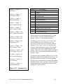
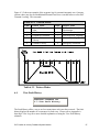
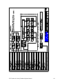
1
PVF Position & Velocity Feedback
System Manual
For Microprocessor-Based Traction
Elevator Controls
NEW: Product Documentation that’s Simple to NavigateTM
This is the PVF Position & Velocity Feedback System Manual to be used with all AC
and DC Traction elevator controllers equipped with this option. Other resources include:
•
•
•
•
•
•
Installation & Adjustment Manual product specific
Field Reprogramming Manual for Model V900/H900 P8 controllers
Drive Specific Manuals
Maintenance & Troubleshooting Training Manual provided in conjunction with Factory
and Customer Site technical training classes
Telephone Technical Support available for Customers at no charge
call: 916/428-1708; fax: 916/428-1728; e-mail: [email protected]
Onsite Product & Engineering Support available worldwide by prior arrangement.
All information contained herein is confidential and proprietary to
Elevator Controls Corporation. This document shall not be used or reproduced,
in whole or part, without the prior written consent of Elevator Controls.
Publication PVF man rev 12/22/06
© 2006 Elevator Controls Corporation
Table of Contents
Introduction & Overview
Page 5
Section 1
1.1
1.2
Installation
PVF Quick Installation Reference Guide
PVF Installation Reference Guide
Page 9
Page 9
Page10
Section 2
2.1
2.2
Main Menu
Startup
Main Menu Operation
Page 18
Page 18
Page 18
Section 3
3.1
3.2
3.3
3.4
3.5
3.6
3.7
3.8
3.9
3.10
3.11
3.12
3.13
3.14
3.15
3.16
3.17
3.18
3.19
Program Variables
Viewing Program
Changing Program Variables
Contract Speed
Number of Floors
Initial Jerk
Roll Over Jerk
Deceleration Jerk
Pattern Delay
Acceleration
Deceleration
Leveling Distance
Leveling Speed
Re-leveling Speed
Inspection Speed
Tach Polarity
Tach Gain
Tach Zero
Leveling Decel Time
Return to Main Menu
Page 19
Page 19
Page 20
Page 21
Page 21
Page 22
Page 23
Page 24
Page 25
Page 26
Page 27
Page 28
Page 29
Page 30
Page 31
Page 32
Page 33
Page 34
Page 35
Page 35
Section 4
4.1
4.2
4.3
4.4
4.5
4.6
4.7
4.8
Hoistway
Viewing the Hoistway Submenu
Setup Mode
Floor Position Table
Terminal Position Table
Terminal Velocity Table
Set Speed Clamps
Terminal Activation Table
Return to Main Menu
Page 36
Page 36
Page 37
Page 38
Page 38
Page 39
Page 39
Page 40
Page 41
PVF Position & Velocity Feedback System Manual
2
Table of Contents Continued
Section 5
5.1
5.2
5.3
5.4
5.5
5.6
5.7
5.8
5.9
5.10
5.11
View Inputs and Outputs
Viewing the Inputs & Outputs Submenu
Tracking Performance
Up Terminals
Down Terminals
Control Signals
Analog Signals
Edge Inputs and Outputs
Elevator MPC Flags
Target and Position
SDI Flags
Return to Main Menu
Page 42
Page 42
Page 43
Page 44
Page 45
Page 46
Page 47
Page 48
Page 49
Page 50
Page 51
Page 52
Section 6
6.1
6.2
6.3
6.4
6.5
6.6
6.7
View Logs
Viewing the View Logs Submenu
View Current Fault
View Sequence Log
View Fault History
Clear Fault History
Last Fault Sequence
Return To Main Menu
Page 53
Page 53
Page 53
Page 54
Page 57
Page 58
Page 59
Page 59
Section 7
7.1
7.2
7.3
7.4
7.5
7.6
7.7
7.8
7.9
7.10
7.11
7.12
7.13
Faults
Following Error
Pulse Failure
Power Supply Error
Floor Count Error
Terminal Count Error
Hoistway Not Learned
Pattern Variable Error
Demand Lost
Motion Signals Lost
Communication Error
Go to Inspection Error
Earthquake Speed
Signals Error
Page 60
Page 61
Page 62
Page 63
Page 65
Page 66
Page 68
Page 69
Page 68
Page 70
Page 71
Page 71
Page 72
Page 72
PVF Position & Velocity Feedback System Manual
3
Table of Contents Continued
Section 8
8.1
8.2
8.3
8.4
8.5
8.6
8.7
8.8
8.9
8.10
8.11
8.12
8.13
8.14
8.15
8.16
8.17
8.18
8.19
8.20
8.21
8.22
8.23
8.24
Troubleshooting
Following Error (0x101, 0x201, 0x301, 0x401, 0x501)
Following Error (0x111, 0x211, 0x311, 0x411, 0x511)
Pulse Error (0x112, 0x122, 0x212, 0x222)
Pulse Error (0x132, 0x142, 0x232, 0x242)
Power Supply Error (0x013 to 0x623)
Floor Count Error (0x114, 0x214)
Floor Count Error (0x104, 0x204)
Terminal Count Error (0x105 to 0x235 and 0x15)
Hoistway Not Learned (0x106)
Pattern Variable Error (0x7, 0x107, 0x207)
Demand Lost (0x108, 0x118, 0x208, 0x218)
Motion Signals Lost (0x119, 0x219, 0x619)
Motion Signals Lost (0x129, 0x229, 0x629)
Motion Signals Lost (0x139, 0x239, 639)
Communication Error (0x10A)
Go to Inspection (0x10B)
Earthquake Speed (0x10C)
Signals Error (0x1D,0x2D,0x3D)
Signals Error (0x4D,0x5D)
No LCD Display
No Safety String
Car Won't Run on Inspection
Car Won't Run on Automatic
Intermittent Shutdowns
Page 73
Page 74
Page 74
Page 75
Page 75
Page 76
Page 77
Page 77
Page 77
Page 78
Page 79
Page 79
Page 79
Page 80
Page 81
Page 81
Page 81
Page 81
Page 82
Page 82
Page 83
Page 83
Page 83
Page 84
Page 84
Section 9
Special Debugging
Page 86
Appendix A Drawings
PVF Position & Velocity Feedback System Manual
Page 91
4
Introduction & Overview
Throughout this manual, icons will be used to call attention to certain areas of text. These
icons represent safety warnings, cautions, and notes.
WARNING: Denotes operating procedures and practices that may result
in personal injury and/or equipment damage if not correctly followed.
CAUTION: Denotes operating procedures and practices that may result in
equipment damage if not correctly followed.
NOTE: Denotes useful information or procedures.
Throughout this manual it is assumed that field personnel are well qualified in the
installation of elevator equipment. No attempt has been made to define terms or
procedures that should be familiar to a qualified elevator mechanic.
Warnings
WARNING: Do not depress the reset button (RESET, SW6) while the elevator is in
motion. This will cause the car to come to an immediate stop.
NOTE: It is assumed that all switches for slowdown, stop, and over travel limits at
both terminal landings have been checked for proper type, placement, and operation.
CAUTION: Equipment installation must be in compliance with all Local and
applicable Elevator and Electrical Codes and regulations.
This manual is intended only to acquaint the service technician with the information required
to successfully install the microprocessor-based elevator controller. Field personnel must be
familiar with all codes and regulations pertaining to the safe installation and operation of the
elevator system.
NOTE: Installation and wiring must be in accordance with the National Electrical
Code and consistent with all local codes, and National elevator codes and regulations.
The AC power supply to this equipment must be provided through a proper fused
disconnect or circuit breaker. Improper protection may create a hazardous condition.
NOTE: Wiring to controller terminals must be done in a neat and careful manner.
Stranded wire conductors must be twisted together to avoid strands that would create
potential shorts if left out of terminals. All terminals and cable connectors must be
checked for proper seating. When connecting flat cable connectors, be certain to
PVF Position & Velocity Feedback System Manual
5
match pin #1 marks (arrow symbol on connectors, red stripe on cable) to prevent
damage.
CAUTION: Restrict access to elevator control equipment and apparatus to qualified
personnel only.
Product Description
The Elevator Controls PVF system is a multi-computer network that controls the elevator.
The PVF uses a dual feedback servo loop from the elevator's speed and position to produce
the optimum ride and performance. Figure I-1 is a block diagram of the PVF multi-computer
network.
Figure I-1 PVF Block Diagram
Elevator Controls Position Velocity Feedback system is comprised of three basic elements, in
addition to the relay logic interface circuitry. These elements are:
1. The elevator car controller computer. It controls all of the elevator sequencing and
signals. The elevator computer is the master computer, and tells the smart drive
interface board (SDI) and the speed regulator what to do.
2. The Smart Drive Interface (SDI). The SDI board generates the optimum speed
pattern. The SDI system receives quadrature pulses from the position transducer. The
SDI system keeps track of the elevators position to within 3/16 of an inch. This
position, along with field adjustable variables, is used to generate an optimum speed
pattern which is fed into the speed regulator.
3. The speed regulator or drive system. The speed regulator makes the elevator follow
the speed pattern produced by the SDI system and control the actual speed and ride of
the elevator.
PVF Position & Velocity Feedback System Manual
6
This manual deals with the Position and Velocity Feedback (PVF) system, including the Smart
Drive Interface (SDI) computer, and it is intended for use in conjunction with the car
controller manual for start up and final adjustment of an Elevator Controls V900 control
system. A specific drive manual for the speed regulator will also be supplied.
PVF uses the basic physical characteristics of motion (jerk rates , acceleration rates, and
deceleration rates) to generate a stepless speed pattern. Figure I-2 illustrates these physical
characteristics. Section 3, Program Variables, shows how each of the characteristics of
motion affects the overall speed pattern.
Figure I-2 Physical Characteristics of Motion
PVF Position & Velocity Feedback System Manual
7
PVF Manual Presented in Eight Sections
Introduction & Overview (this Section) provides a system overview.
Section 1 covers installation and adjustment of the SDI computer and related hoistway
equipment. The SDI computer user interface has a main menu and four submenus.
Section 2 describes main menu options and how to access submenus.
Sections 3 through 6 explain each of the submenus in detail including how each is used
and viewed.
Section 7 describes each of the faults. It explains all of the error codes and what they
mean.
The appendix contains a detailed description of all the key strokes necessary to
navigate the SDI menus.
NOTE: The SDI's LCD display contains 4 basic menus, with each basic menu
containing several submenus. When reference is made to these menus/submenus in
this manual, the submenu number and name is indicated as it is displayed on the LCD.
For example: "1.10 Leveling Speed" refers to basic menu 1, submenu 10. It does not
indicate page 1.10 or Section 1.10 in this manual. Likewise, the reference "submenu
2.1 Setup Mode" indicates submenu 2.1 and not page 2.1 or Section 2.1 in this
manual. Section and page number references will be indicated with the words
"Section" and "page" respectively.
WARNING: The position transducer on the cartop uses optical sensors to read tape
holes. It is important to keep the sensors and reflector clean from dust and debris,
particularly on new installations where dust and dirt is excessive. Do not grease the
center of the tape to prevent reflection and to keep the optical readers clean.
PVF Position & Velocity Feedback System Manual
8
Section 1 – Installation
1.1
NOTE: Sections 1.1 and 1.2 below are provided for installation/adjustment reference.
Please refer to corresponding V900 manual for procedures corresponding to the type
of controller you are installing or adjusting.
PVF Quick Installation Reference Guide
This guide provides an overview of installing and adjusting the SDI boards. Users who are
already familiar with the PVF installation process can quickly review the steps here. Users
who are not yet comfortable with these steps should read all references cited in each step
before starting the SDI setup procedure. The installation instructions following this Section
go into greater detail for each step.
1.1.1
Verify Factory Settings
Verify factory setting for: contract speed, number of floors, tach polarity, tach gain and tach
zero. Use submenus 1.1 Contract speed (See PVF User’s Manual Section 3-3), 1.2 Number
of Floors (See PVF User’s Manual Section 3-4), 1.13 Tach Polarity (See PVF User’s Manual
Section 3-15), 1.14 Tach Gain (See PVF User’s Manual Section 3-16) and 1.15 Tach Zero
(See PVF User’s Manual Section 3-17).
1.1.2
Verify Floor Landing Magnets
Verify floor landing magnets are installed and adjusted so that car is floor level at each
landing. Verify all terminal slowdowns are installed and adjusted as specified on your
hoistway print. Go to submenu 3.8 Target and Position. Run car up on inspection; verify that
the DP value goes up. Run car down on inspection and verify that the DP value goes down.
If DP value increments in the wrong direction, reverse DP1 and DP2 wires.
1.1.3
Verify Pattern Clamps
Verify that all pattern clamps are set according to table below using submenu 2.5 Set Speed
Clamps. Some clamps will not be available for your job, turn the corresponding trimpot 20
turns counter-clockwise for all unused clamps. Ignore the displayed value for T1 through T14
for now. See PVF User’s Manual Section 4-6.
Table 1.1-1 Initial Clamp Settings Before Final Adjustment
Terminal &
Resistor Number
T1, R55
T2, R54
T5, R53
T6, R58
T7, R59
Pattern Clamp
P = 20 FPM
P = 250 FPM
P = 350 FPM
P = 500 FPM
P = 600 FPM
PVF Position & Velocity Feedback System Manual
Terminal &
Resistor Number
T8, R60
T10, R61
T12, R50
T14, R57
Pattern Clamp
P = 700 FPM
P = 800 FPM
P = 1000 FPM
P = 1200 FPM
9
1.1.4
Move Car on Inspection to “Learn the hoistway”
Move car on inspection on down travel limit. Jumper “SDI Learn” jumper on Relay board.
Select hoistway learning program with submenu 2.1 Setup Mode. Run up without stopping to
upper travel limit on inspection. Remove jumper SH5. See PVF User’s Manual Section 4-2.
1.1.5
Verify Floor Positions
Verify all floor positions with submenu 2.1 Floor Position Table. All of the pulse counts
should be greater than 1000. See PVF User’s Manual Section 4-3. Verify all terminal
slowdown positions with submenu 2.3 Terminal Pos Table. See PVF User’s Manual Section
4-4.
1.1.6
Adjust Re-level Speed
Move car on inspection above the first floor onto LD (level down). Disable door(s) with
TEST switch. Remove inspection and allow car to re-level into the floor. Adjust re-level
speed with variable 1.11 Re-level Speed for accuracy and comfort. Repeat as needed. See
PVF User’s Manual Section 3-13.
1.1.7
Adjust Pattern
Adjust pattern for comfortable ride and shortest brake-to-brake time. Make one and two
floor runs up on TEST mode with the door disabled. Adjust pattern delay, initial jerk,
acceleration, roll-over jerk, deceleration jerk, deceleration, leveling distance and leveling
speed variables. An oscilloscope is very useful here. See PVF User’s Manual Sections 3-5
through 3-12.
1.1.7
Adjust Clamp Voltages
After completing step 1.1.7, move car to bottom level with doors disabled. Run car up to top
level, then run back down to bottom level. Adjust all clamp voltages with submenu 2.5 Set
Speed Clamps for the speed indicated on the LCD. See PVF User’s Manual Section 4-6.
1.2
NOTE: If you readjust any of the parameters listed in step 2.17, you must repeat this
step.
Installation Reference Guide
This installation guide provides more detailed information than the previous Section. Read
this entire Section before you attempt any of the steps. This will speed the installation
process. This Section is also a final adjustment for the SDI unit.
1.2.1
Follow Startup Procedure
Read and follow the start up procedure in the Model V900 Controller Manual. You should
also read the manual for your type of drive, as supplied by the manufacturer.
PVF Position & Velocity Feedback System Manual
10
1.2.2
Note Signal Controls
Note that the signal controls supplied to the SDI system are: UP, DN and ENA (enable) as
well as INS (inspection mode). These inputs are connected via relay logic and are the
minimum signals the SDI system needs to generate a pattern. To run on inspection (required
during the start up procedure) these inputs must be active as follows:
Table 1.2-1 SDI System Inspection Mode
Operation
Inspection Run Up
Inspection Run Down
Inspection Mode
Stopped
INS
110VDC
110VDC
110VDC
UP
0VDC
15VDC
15VDC
DN
15VDC
0VDC
15VDC
ENA
0VDC
0VDC
5VDC
If these inputs are not active then you will need to determine the cause. Normally a problem
here is caused by an open safety string or open limit switch.
1.2.3
Pre-Operation Checklist
Follow the pre-operation checks listed in the drive's installation manual, if the start up
procedure in the Model V900 Controller Manual directs you to do so.
1.2.4
Check Voltage
Check the voltage on the line side of the disconnect for correct supply voltage. Turn the
disconnect off and remove relay logic supply, hall supply and door operator supply fuses.
1.2.5
Check All Terminals
With power off, check all terminals for a direct short to ground (usually less than 100 ohms to
the 3 bus terminal). Stop if there is a problem and correct it. Turn power on and check the
supply voltages on L1, L2, L3 terminals on the controller. Replace the relay logic supply fuse.
1.2.6
WARNING: Power capacitors will remain charged for some time after power is
removed from the system.
Turn on Power
Turn on power. With a PVF system, the SAF relay should not pick until the system is placed
on inspection. If SAF does not pick when on inspection, refer to the safety circuit on your job
prints.
1.2.7
Initial Drive Setup
Refer to the Model V900 Controller Manual; setup the drive with the initial values specified
for your drive.
The SDI system also needs a correct initial setup; this is done at the factory. You should
verify the setup yourself before attempting to run on inspection. See PVF User’s Manual
PVF Position & Velocity Feedback System Manual
11
Section 2 Program Variables. The following parameters must be set correctly: 1.1 Contract
Speed (See PVF User’s Manual Section 3-3), 1.2 Number of Floors (See PVF User’s Manual
Section 3-4), 1.13 Tach Polarity (See PVF User’s Manual Section 3-15), 1.14 Tach Gain (See
PVF User’s Manual Section 3-16) and 1.15 Tach Zero (See PVF User’s Manual Section 317).
1.2.8
Check Inspection Speed
Check that program variable 1.12 Inspection Speed is set reasonably on the SDI system. You
should start with a very low inspection speed (about 25 FPM) and increase this gradually in
step 10. See Section 3.14 of the PVF User’s Manual.
1.2.9
Verify Pattern Clamps Initial Setting
The pattern clamps need to be set correctly. This is not a final adjustment. The factory
should set the clamps to the values below. Verify these values on the SDI system using
submenu 2.5 Set Speed Clamps. Some clamps may not be used on your job; if your contract
speed is less than the value shown below, that clamp will be unused, turn the corresponding
trimpot 20 turns counter-clockwise for all unused clamps. See PVF User’s Manual Section
4.6.
Table 1.2-2 Initial Clamp Settings Before Final Adjustment
Terminal &
Resistor Number
T1, R55
T2, R54
T5, R53
T6, R58
T7, R59
1.2.10
Pattern Clamp
P = 20 FPM
P = 250 FPM
P = 350 FPM
P = 500 FPM
P = 600 FPM
Terminal &
Resistor Number
T8, R60
T10, R61
T12, R50
T14, R57
Pattern Clamp
P = 700 FPM
P = 800 FPM
P = 1000 FPM
P = 1200 FPM
Attempt Run
With the controller on inspection mode, try to run using the UP/DN switch on the controller.
You may have to connect a temporary jumper across the door inter-lock. The cartop
inspection switch must be off to run from the controller. If the car runs backwards, refer to
the Model V900 Controller Manual for the correct procedure for reversing the direction for
your system.
You will also have to adjust the brake picking voltage at this time. See the drive page of your
job prints for the adjustments to any brake resistors
1.2.11
Set Inspection Speed
Now increase program variable 1.12 Inspection Speed on the PVF system to the value you
want. Do this in two or three steps. For example, increase inspection speed first to 50 FPM.
Run the car up a few floors, then down the same way. The hoistway should be clear of
obstructions before you do this. Finally, you can now set 1.12 Inspection Speed to the value
you want.
PVF Position & Velocity Feedback System Manual
12
1.2.12
Check Brake
Make sure the brake will hold at least an empty car.
1.2.13
Check Overtravel Limits
The over-travel limits must be adjusted to the values specified on your job hoistway print.
The elevator should now be completed. Test all safety circuits before continuing with the
installation. Be sure that opening over-travel limits or safety string will remove power from
the controller and stop the car. Check that the car will not move if the inspection mode is off.
Test any other safeties that you will use during the installation, ie: the pit switch. With power
off, test all terminals for grounds, as you did in step 1.2.5. Remedy any problems before
proceeding.
1.2.14
Verify Proper Connector Seating
Verify all connectors in the system are correctly seated, if you haven't done so before. Ribbon
and plugable field wire connectors can wiggle loose when the system is being worked on.
Press firmly on all connectors to seat them.
NOTE: At this point the system should run correctly on inspection. If you are still
having problems, review steps 1 through 14 and repeat as necessary.
Before running the system on automatic, follow steps 1.2.15 through 1.2.26. This includes
the final adjustment of the elevator.
1.2.15
Adjust Terminal Slowdowns
The terminal slowdowns and over-travel limits must be adjusted to the values specified on
your job hoistway print.
1.2.16
Set Leveling Switches
Set the leveling switches on the car top to give proper dead zone, +/- 1/4". For PVF system,
LU and LD need to be off (0VDC) when the car is level. This is different than some DUPAR
magnetic switch systems; however the vane lengths and switch arrangements are specified
correctly on your job information. Use two twisted shielded pairs for the digital pulse output
from the selector. Connect DP1 and DPC each to one wire in the first shielded pair. Connect
DP2 and DPC each to one wire in the second shielded pair. DP1 and DP2 are each labeled on
the SDI system and the selector. DPC on the SDI system connects to selector power supply 0
volts common. See your drive or PVF prints for a correct wiring schematic.
You cannot set the re-level speed yet, since the PVF system will only run on inspection at this
point.
1.2.17
Test Digital Pulse (DP) Inputs
Test the DP1 and DP2 inputs to the SDI board. Use submenu 3.8 Target and Position. Run
the car up on inspection; verify that the DP (digital pulse) value goes up. Run car down on
PVF Position & Velocity Feedback System Manual
13
inspection; verify that the DP value goes down. If the DP value goes in the wrong direction,
reverse the DP1 in DP2 wires on the SDI system.
1.2.18
Adjust Door Operator
The door operator must be correctly adjusted. Remember to reinstall the door fuses.
Clutches must have proper clearances for running in the hoistway. Check the print for any
special instruction on your job.
1.2.19
Check for Obstructions
Make sure all hoistway doors and car doors are closed and locked. Run the car on inspection
mode through the entire hatch, making sure it is clear of obstructions. Door zone and level
vanes should already be installed and adjusted to level the car within 1/4" of the floor.
1.2.20
Learn the Hoistway
The SDI system now needs to learn the hoistway. This procedure is fully detailed in the PVF
User’s Manual Section 4.2 Setup Mode.
1.2.21
Verify Floor Position Table
After completing step 20, verify that the floor position table is correct. Use submenu 2.2
Floor Position Table on the SDI system. Press the UP button on this menu, observing the
recorded position for each floor. The floor positions are shown in two ways: feet (FT) and
pulses (P), about 3/16 inch. These values should be reasonable and correspond to what you'd
expect the floor heights to be. Most floors should be eleven to twelve feet apart. If one floor
has a mezzanine or high ceiling, the next floor should have more rise. Any of the following
indicate a problem:
1. All of the floor positions are the same. Floor heights are measured relative to the
bottom limit. They normally increase 11 ft each floor: 0 ft, 11 ft, 22 ft, 33 ft, 44 ft etc.
2. Floor positions decrease or are negative. Pulse counts are less than 1000P. Floors
should start at 0 ft and go up from there. The pulse counts are set to 1000P at the
bottom limit and go up from there.
If you do find a problem, check your field wires, especially DP1, DP2, DPC and door and
level switches. Then go back to step 1.2.17. Repeat steps 1.2.20 and 1.2.21 once you find
the problem.
1.2.22
Verify Terminal Slowdown Table
Verify that the terminal slowdown position table is correct. Use submenu 2.3 Terminal Pos
Table on the SDI system. Press the UP button on this menu, observing the recorded positions
for each terminal. Like the floor position table, these values should be reasonable and
correspond to what you'd expect the terminal positions to be. Any of the problems given in
step 1.2.21 apply to the terminal slowdowns.
PVF Position & Velocity Feedback System Manual
14
If you do find a problem, check your field wiring. Verify that the slowdowns are set in the
correct positions. Go back to step 1.2.17. Then repeat steps 1.2.20, 1.2.21 and 1.2.22 once
you have found the problem.
1.2.23
Test Operation
Now move the car to the second level. Move the TEST switch to the on position. This will
put the system on independent mode when inspection mode is turned off. TEST also disables
door opening (TEST mode does NOT disable door closing). Move the car below the floor
onto the leveling input with the inspection switch, then turn inspection off. The car should relevel up into the floor. Check that the relays sequence properly for re-leveling and adjust the
program variable 1.11 Re-level Speed for accuracy and comfort.
Put the system back on inspection and repeat step 1.2.23 as needed. Then repeat by moving
the car above the floor to get a re-level down, repeating as needed.
1.2.24
Inspection Off
Turn inspection mode off (TEST should still be on from step 1.2.23). Place a car call one
floor above the second level. The car will run up from the second level and slowdown into
the third floor. Observe how the system responds, especially the brake, motor and sheave.
Decide what part of the system needs to be adjusted first and focus on that. You may need to
stop and readjust other parts of the system during this procedure. Any problems with the
brake or door clutch clearances will become apparent here. Correct these problems as they
come up before continuing with this adjustment.
NOTE: To place car calls from the machine room, connect a wire to the 3 bus
terminal on the HLS board. Touch this wire to the car call field terminals on the I/O-6
board to place a call.
Adjusting the pattern can be more of an art than a science. You have two goals: ride comfort
and brake-to-brake time. You will have to decide which to work on at any one time. The
two goals are not exclusive; you can achieve both. You will need to make numerous runs to
be sure that the system responds how you want. Take your time here; adjustment procedures
are not inherently quick.
NOTE: A dual-trace storage oscilloscope can be a great help here. Observing the
pattern output and the tach from the drive can save a lot of time and hassle. Connect
one probe on the PUP output from the SDI system. PUP is "pattern up" and is a 0 to
10 volt positive signal. Connect the second probe on the TAC (tachometer) input to
the SDI system. This is -10V to 10V input to the SDI, although some drives supply
0V to 8V or 0V to 5V (check your drive manual). 0V on TAC always indicates zero
speed.
NOTE: A pair of hand-held radios and a helper can be a great help. After the speed
pattern is adjusted as well as possible from the machine room, the adjuster should ride
PVF Position & Velocity Feedback System Manual
15
the car while a helper adjusts the system per the adjuster's instructions. There is
simply no substitute for riding a car while adjusting.
As you adjust the parameters below, refer to the relevant Sections in the PVF User’s Manual.
These Sections contain explanations and illustrations to help you adjust the SDI system.
1.2.24.1 Decreasing Brake-To-Brake Time
A. Increase 1.7 Acceleration. See Section 3.9 in this manual.
HINT: When you do this, you will probably have to increase 1.3 Initial Jerk and 1.4
Roll-Over Jerk. The jerk values should be 1.4 to 1 times the Acceleration value.
Example: if Acceleration is set to 200 FPM/s, Initial Jerk and Roll Over Jerk should be
set between 200 FPM/s/s and 280 FPM/s/s.
B. Increase 1.3 Initial Jerk and 1.4 Roll Over Jerk. See Sections 3.5 and 3.6 in this
manual.
HINT: Both of these parameters should be changed whenever 1.7 Acceleration is
changed significantly. For quick brake-to-brake times, use 1.4 times the Acceleration.
value. Higher jerk values will cause the pattern to reach contract speed quicker.
C. Increase 1.8 Deceleration. See Section 3.10 in this manual.
HINT: your Deceleration value will probably have to be 25 to 50 FPM/s less than your
Acceleration value. This improves passenger comfort and also makes final approach
into the floor more accurate.
D. Decrease 1.9 Leveling Distance. See Section 3.11 in this manual.
HINT: The leveling distance is used in place of a final (stopping) jerk. An oscilloscope
is very useful for viewing the shape of the final curve. Also, leveling distance is
measured in pulses from the tape, 3/16 of an inch. You'll have to make larger changes
of this value-at least six to ten pulses-to see any change in performance.
HINT: Leveling distance must always be greater than 16, which is only 3" of
controlled floor targeting. Leveling distance should normally always be greater than
32. A good working range is 72P to 38P.
1.2.24.2 Improving Passenger Comfort
A.
Increase 1.6 Pattern Delay. See Section 3.8 in this manual.
NOTE: This is only useful if the car is pulling through the brake when the pattern
starts. Increasing pattern delay will wait for a given amount of time, allowing the
break to pick.
B. Decrease 1.10 Leveling Speed. See Section 3.12 in this manual.
HINT: Leveling speed is set high at the factory so a car won't stall coming into a
floor. You will need to decrease leveling speed to about 4 FPM to eliminate the bump
when stopping in most systems.
C. Decrease 1.3 Initial Jerk. See Section 3.5 in this manual.
PVF Position & Velocity Feedback System Manual
16
HINT: Excessively high jerk values can cause passenger discomfort.
HINT: Some motor systems can not follow high jerk values. The resulting overshoot
can cause bumps during the ride. You need a dual trace storage oscilloscope on the
TAC input to the SDI system to determine this. Decrease the initial jerk until you can
see a smooth start on the tachometer from the drive.
D.
Decrease 1.4 Roll Over Jerk. See Section 3.6 in this manual.
See part G above for hints on how to do this.
E. Decrease 1.5 Deceleration Jerk. See Section 3.7 in this manual.
See part G above for hints on how to do this.
1.2.25
Final Pattern Clamp Adjustment
After step 1.2.24 is complete, the pattern clamps must be adjusted. With TEST mode still
on, run the car to the bottom floor. Then make one complete run of the hoistway up to the
top terminal. Run back down to the bottom terminal in one run. Now use submenu 2.5 Set
Speed Clamps on the SDI system. The system will display the proper value for the speed
clamp and the potentiometer to adjust. Note: these values will be different than those set as
initial values in step 3. This time you will use the displayed value for T1 through T14. Press
the UP button on the SDI system and repeat for the next clamp. Repeat until all of the clamps
are adjusted.
1.2.26
NOTE: If you change any velocity pattern variable, the clamps may need to be readjusted. Repeat this step any time you adjust Initial Jerk, Acceleration, Roll Over
Jerk, Deceleration Jerk, Deceleration or Leveling Distance.
Re-Verify Proper Connector Seating
Verify all connectors in the system are correctly seated, if you haven't done so before. Ribbon
and plugable field wire connector can wiggle loose when the system is being worked on.
Press firmly on all connectors to seat them.
PVF Position & Velocity Feedback System Manual
17
Section 2 – Main Menu
2.1
2.2
2.1
Start Up
Ma in Menu Operation
Startup
When the SDI is first powered up, or when the SDI reset button is pressed, the LCD will
display the following message after one second:
ELEVATOR CONTROLS
MAIN MENU
You can now use the SDI main menu described below.
2.2
Main Menu Operation
The SDI main menu has four items which can be displayed one at a time. Scroll through the
menu items by pressing the UP or DOWN buttons on the SDI system. To work with the
currently displayed menu item press the SELECT button. Each of these submenu items is
discussed in detail in Sections 3 through 6. See those Sections for greater explanation.
The four main menu items are listed in Table 2.2-1.
Table 2.2-1 Main Menu Items
1. Program Variables
2. Hoistway
3. View I/O
4. View Logs
For an example of how to use the main menu refer to drawing SDI 7A in appendix A
NOTE: For information on the special purpose menu: "5. Special Debugging" refer to
Section 9 in this manual. The special debugging menu has submenus dealing with
hardware troubleshooting, programming faults auto-resets, clearing SDI memory, etc.
PVF Position & Velocity Feedback System Manual
18
Section 3 – Program Variables
3.1
3.2
3.3
3.4
3.5
3.6
3.7
3.8
3.9
3.10
3.11
3.12
3.13
3.14
3.15
3.16
3.17
3.18
3.19
3.1
Viewing Program Variables
Changing Program Variables
Contract Speed
Number of Floors
Initial Jerk
Roll Over Jerk
Deceleration Jerk
Pattern Delay
Acceleration
Deceleration
Leveling Distance
Leveling Speed
Re-leveling Speed
Inspection Speed
Tach Polarity
Tach Gain
Tach Zero
Leveling Decel Time
Return to Main Menu
Viewing Program Variables
ELEVATOR CONTROLS
1. PROGRAM VARIABLES
Press SELECT on the program variable menu, shown above, to view the program variables.
Program variable items may be viewed in the same manner as the main menu. Pressing UP
selects the next item in the list. Pressing DOWN selects the previous item in the list. Leveling
speed is shown below as an example of viewing a program variable. Please refer to Appendix
A drawing SDI Submenu 1 for a more detailed description of how to select submenu 1 items.
1.10 Leveling Speed
Is = 6 FPM
PVF Position & Velocity Feedback System Manual
19
Table 3.1-1 lists all of the program variables available.
Table 3.1-1 Program Variables
1.1
1.2
1.3
1.4
1.5
1.6
1.7
1.8
3.2
Contract Speed
Number of Floors
Initial Jerk
Roll Over Jerk
Deceleration Jerk
Pattern Delay
Acceleration
Deceleration
1.9 Leveling Distance
1.10 Leveling Speed
1.11 Re-leveling Speed
1.12 Inspection Speed
1.13 Tach Polarity
1.14 Tach Gain
1.15 Tach Zero
1.16 Return to Main Menu
Changing Program Variables
To change a parameter move the READ/EDIT toggle switch to the EDIT position. Push the
UP or DOWN button to select the program variable to change, then press SELECT (to select
a program variable press UP or DOWN until it is displayed. See Appendix A drawing SDI
7B). SELECT has no effect if the READ/EDIT switch is in the READ position.
After pressing SELECT on a submenu item, the second display line will change to:
"New Value ="
An example is shown below.
1.7 Acceleration
New Value = 200 FPM/S
Now the UP and DOWN buttons affect the value displayed rather than the submenu item
displayed. If you press UP or DOWN consecutively more than 10 times, the value will change
faster, enabling large changes to be made more quickly.
After setting the variable to the value you want, press SAVE to record the value permanently
in the SDI's memory. If you make a mistake, you can return to the submenu without
recording the changed value by pressing SELECT. The original value will be restored.
The SDI button operation is summarized below.
PVF Position & Velocity Feedback System Manual
20
Table 3.2.1 Changing Program Variables
UP
*
*
*
*
*
*
*
Add 1 to value if 1 to 10 consecutive presses
Add 10 to value if 11 to 20 consecutive presses
Add 100 to value if 21 or more consecutive presses
Add 1 to value if 1 to 10 consecutive presses
Add 10 to value if 11 to 20 consecutive presses
Add 100 to value if 21 or more consecutive presses
Abandon your changes. Returns the variable to its
original value. Returns to variable sub-menu item
display.
* Returns to submenu item, saving the variable's new
value.
DOWN
SELECT
SAVE
3.3
Contract Speed
1.1 Contract Speed
Is = 1400 FPM
RANGE: 25 - 1400 FPM
UNITS: feet per minute
The contract speed variable sets the scale values for all other parts of the SDI. This parameter
must be set correctly for the rest of the drive to function properly.
Change this value to the contract speed for this car. The value is set to the speed you
specified on your data sheets.
3.4
Number of Floors
1.2 Number of Floors
Is = 24
RANGE: 2 - 63
UNITS: none
The number of floors should be set equal to the total number of floors serviced by this car.
This value is set at the factory to the value specified on your data sheets.
PVF Position & Velocity Feedback System Manual
21
3.5
Initial Jerk
1.3 Initial Jerk
Is = 192 FPM/S/S
RANGE: 25 - 500
UNITS: feet per minute per second per second
The initial jerk variable controls the softness of the start of the velocity pattern. Larger values
result in a greater g-force felt in the car when starting. With larger jerk values, the pattern
also spends less time in rounding and reaches contract speed sooner.
The exact amount of time spent in rounding depends on the acceleration rate. The time is
(acceleration ÷ initial jerk) and should normally be 0.6 to 1.3 seconds. You can easily set a
one second round by setting the jerk numerically equal to the acceleration. If the acceleration
is 200 FPM/S, the an initial jerk value of 200 FPM/S/S will give one second of initial
rounding.
The jerk should not be so low that the drive cannot reach contract speed. The initial rounding
should never take more than one half of the total time to reach contract speed. The minimum
jerk Jmin is equal to:
Jmin =
2
Figure 3.5-1 Initial Jerk
PVF Position & Velocity Feedback System Manual
22
3.6
Roll Over Jerk
1.4 Roll Over Jerk
Is = 192 FPM/S/S
RANGE: 25 - 500
UNITS: feet per minute per second per second
The roll over jerk variable controls the softness of the switch to constant velocity of the
velocity pattern. Larger values result in a greater g-force felt in the car when attaining
maximum speed. With larger jerk values, the pattern also spends less time in rounding and
reaches contract speed sooner. If the car over shoots contract speed, decreasing the roll over
jerk will reduce the over shoot.
The exact amount of time spent in rounding depends on the acceleration rate. The time is
(acceleration ÷ roll over jerk) and should normally be 0.6 to 1.3 seconds. You can easily set a
one second rounding time by setting the jerk numerically equal to the acceleration. If the
acceleration is 200 FPM/S, the an roll over jerk value of 200 FPM/S/S will give one second of
roll over rounding.
The jerk should not be so low that the drive cannot reach contract speed. The roll over
rounding should never take more than one half of the total time to reach contract speed. The
minimum jerk Jmin is equal to:
Jmin =
Figure 3.6-1 Roll Over Jerk
PVF Position & Velocity Feedback System Manual
2
Figure 3.6-2 Overshoot
23
3.7
Deceleration Jerk
1.5 Deceleration Jerk
Is = 192 FPM/S/S
UNITS: feet per minute per second per second
The roll over jerk variable controls the softness of the switch from constant velocity to
constant deceleration. Larger values result in a greater g-force felt in the car when rounding
into constant deceleration. With larger jerk values, the pattern also spends less time in
rounding and reaches leveling speed sooner.
The exact amount of time spent in rounding depends on the deceleration. The time is
(deceleration ÷ deceleration jerk) and should normally be 0.6 to 1.3 seconds. You can easily
set a one second rounding time by setting the jerk numerically equal to the deceleration. If the
deceleration is 200 FPM/S, the an deceleration jerk value of 200 FPM/S/S will give one
second of deceleration rounding.
The jerk should not be so low that the drive cannot slowdown from contract speed. The
deceleration rounding should never take more than one half of the total time to reach leveling
speed. The minimum jerk Jmin is equal to:
Jmin =
2
Figure 3.7-1 Deceleration Jerk
PVF Position & Velocity Feedback System Manual
24
3.8
Pattern Delay
1.6 Pattern Delay
Is = 0 X 0.01 S
RANGE: 0 - 200
UNITS: hundredths of seconds
Pattern delay keeps the pattern at zero speed for the amount of time you specify after the
enable comes in. (The enable input is located on the MPC-SDI board and is labeled ENA.
Enable usually activates at the same time as the UP or DN relays pick). Use pattern delay to
compensate for a sluggish picking brake. If your car pulls through the brake at start, increase
this variable. Increasing pattern delay will hold zero pattern for a longer time at the start,
allowing the brake to pick before the pattern and the car begin to accelerate.
Figure 3.8
Pattern Delay
PVF Position & Velocity Feedback System Manual
25
3.9
Acceleration
1.7 Acceleration
Is = 142 FPM/S
RANGE: 25 - 300
UNITS: feet per minute per second
The acceleration controls the rate at which the car reaches contract speed. The higher the
acceleration value the sharper the rate. For example, with Contract Speed set at 350 FPM,
and Acceleration set to 100 FPM/S, the car will reach contract speed in 3.5 seconds. This
calculation is before rounding is considered. Each rounding corner will normally add about
half of its rounding time to the time to reach contract speed.
This variable is also used to control the pattern ramp-up for inspection mode and during a relevel. Changing this parameter will change the rate at which an automatic run pattern,
inspection pattern and a re-level pattern all attain their respective rated speeds.
Remember that changing the acceleration will affect the time spent in rounding. Each
rounding corner will normally add about half of its rounding time to the time to reach contract
speed. See Sections 3.5 Initial Jerk and 3.6 Roll Over Jerk for an explanation of how
rounding works.
Note: Divide FPM/S by 60 to get ft/s2.
Figure 3.9 Acceleration
PVF Position & Velocity Feedback System Manual
26
3.10
Deceleration
1.8 Deceleration
Is = 142 FPM/S
RANGE: 25 - 300
UNITS: feet per minute per second
The deceleration controls the rate at which the car reaches leveling speed. The higher the
deceleration value the sharper the rate. For example, with Contract Speed set at 350 FPM,
and Deceleration set to 100 FPM/S, the car will reach leveling speed in 3.5 seconds. This
calculation is before rounding is considered. Each rounding corner will normally add about
half of its rounding time to the time to reach contract speed.
Remember that changing the deceleration will affect the time spent in rounding. See Sections
3.7 Deceleration Jerk for an explanation of how rounding works.
Note: Divide FPM/S by 60 to get ft/s2.
Figure 3.10-1 Deceleration
PVF Position & Velocity Feedback System Manual
27
3.11
Leveling Distance
1.9 Leveling Distance
Is = 64 P
RANGE: 0 - 128
UNITS: Pulses (= 3/16 inches)
Leveling distance controls when the car begins targeting the floor. The larger the value, the
further away targeting begins. Leveling distance also controls the softness of the final
rounding during an automatic run. Larger values produce softer approaches to the floor.
Leveling distance works with leveling speed to determine how the car comes into a floor.
High values of leveling distance and low speeds for leveling speed produce more accurate and
softer approaches to the floor. Reducing leveling speed will reduce the stop shock as the
brake sets. However softer and more accurate approaches also mean longer brake-to-brake
times.
Figure 3.11-1
Leveling Distance
PVF Position & Velocity Feedback System Manual
28
3.12
Leveling Speed
1.10 Leveling Speed
Is = 4 FPM
RANGE: 0 - 50
UNITS: feet per minute
Leveling Speed controls the final speed of the car when coming into a floor. Increasing
leveling speed will increase this final speed.
Decreasing leveling speed will reduce the stop shock felt when the break sets. If the leveling
speed is set too high it will cause the car to over-shoot the floor. Leveling Distance will
probably better control over-shoot if the leveling speed is set reasonably.
Figure 3.12-1 Leveling Speed
PVF Position & Velocity Feedback System Manual
29
3.13
Re-leveling Speed
1.11 Re-leveling Speed
Is = 4 FPM
RANGE: 4 - 50
UNITS: feet per minute
Re-leveling speed controls what speed the car ramps-up to when a re-level is required. Higher
values in re-leveling speed result in faster speeds during a re-level. Program variable
Acceleration controls the rate at which the car reaches re-leveling speed. The higher the
acceleration value the sharper the rate.
Figure 3.13-1
Re-leveling Speed
PVF Position & Velocity Feedback System Manual
30
3.14
Inspection Speed
1.12 Inspection Speed
Is = 100 FPM
RANGE: 0 - 150
UNITS: feet per minute
Inspection speed controls what speed the car ramps-up to when on inspection mode. Higher
values in inspection speed result in faster speeds during movement on inspection. Program
variable Acceleration controls the rate at which the car reaches inspection speed. The higher
the acceleration value the sharper the rate.
Figure 3.14-1 Inspection Speed
PVF Position & Velocity Feedback System Manual
31
3.15
Tach Polarity
1.13 Tach Polarity
Is = Positive Up Bi-directional
Tach polarity matches the tachometer input on the SDI to the direction of the car. This
parameter is set at the factory and is correct for the type of drive included with your system.
However you can check this parameter with a meter. Put the car on inspection and move the
car up and down, checking the voltage on the tach input to the MPC-SDI board, labeled TAC,
relative to ground (GND). Refer to table 3.15-1. Table 3.15-2 shows typical settings for
some drives used.
Table 3.15-1 Tach Polarity
Positive Up Tach
Positive Down Tach
Positive Tach
Negative Tach
Direction on
Inspection
UP
DOWN
UP
DOWN
UP
DOWN
UP
DOWN
Polarity on
TAC
Positive
Negative
Negative
Positive
Positive
Positive
Negative
Negative
Table 3.15-2 Typical SDI Tach Settings for Various Drives
Drive
Yaskawa Vector
Magnetek HPV900/600
KEB Combivert F5
Magnetek DSD412 SCR drive
Control Techniques Mentor II
EDGE
SWEO Digital SCR (ABS Speed)
SWEO Analog SCR
PVF Position & Velocity Feedback System Manual
Tach polarity
Positive Up Tach
Positive Up Tach
Positive Up Tach
Positive Up Tach
Positive Down Tach
Positive Down Tach
Positive Tach
Positive Down Tach
Tach gain
100%
100%
100%
100%
100%
100%
50%
80%
32
3.16
Tach Gain
1.14 Tach Gain
Is = 100%
RANGE: 75 - 105
UNITS: percent
Tach gain is used to scale the tachometer input to the SDI for the particular drive being used.
This parameter is set correctly in the factory and does not need to be set in the field. However
you may adjust this parameter slightly to tune the tachometer feet-per-minute display in 3.1
Tracking Performance. THE CAR SPEED MUST ALREADY BE CORRECT. CHECK
THE CAR SPEED WITH A HAND TACH BEFORE ADJUSTING THIS PARAMETER.
You cannot compensate for a car that is not running at the correct contract speed by adjusting
this parameter. You can only fine tune the tach display or configure the tach for a different
drive input.
To fine tune the tach gain, run the car at constant speed and measure the car speed with a
hand tachometer. Compare this value at the same time with the tach speed shown in 3.1
Tracking Performance. If the speed displayed on the LCD is greater than the actual speed,
increase tach gain until they are equal. If the speed displayed on the LCD is less than the
actual speed, decrease tach gain until they are equal. Please refer to Section 3.15, table 3.15-2
for some typical tach gain settings for certain drives.
Figure 3.16-1 Tach Gain
PVF Position & Velocity Feedback System Manual
33
3.17
Tach Zero
1.15 Tach Zero
Is = 480
RANGE: 0 - 1024
UNITS: (internal)
This parameter is used to adjust the electrical zero value for the tachometer on the SDI. It
compensates for variations in component tolerance and is set correctly at the factory for your
equipment. You will need to reset this parameter when replacing SDI boards, or when
replacing "Ram" chip, or after a "memory reset procedure". This parameter will only adjust
the value display on the LCD in Section 4.1 Tracking Performance. YOU CANNOT CAUSE
THE DRIVE TO HOLD ELECTRICAL ZERO, OR AFFECT THE CAR PERFORMANCE
IN ANY WAY BY ADJUSTING THIS PARAMETER.
You can verify that this parameter is set correctly in the field. With the car stopped
(preferably on inspection) and submenu item 1.15 displayed, press the SELECT and then
SAVE buttons. The READ/EDIT switch must be in the EDIT position. The system will read
the voltage on the TAC input to the SDI and accept this as zero for this drive. The system
will display the value it reads, scaled to internal units. Values from 460 to 500 are typical.
IF YOU GET A VALUE OUT SIDE OF THE RANGE 460 - 500, YOU HAVE A
SERIOUS PROBLEM. DO NOT ATTEMPT TO RUN THE CAR ON AUTOMATIC.
Verify that the car was in fact stopped and the tach is connected as instructed. You may need
to check the drive programming for the proper tach input to the SDI. Call the factory if you
cannot resolve the problem.
PVF Position & Velocity Feedback System Manual
34
3.18
Leveling Deceleration Time
1.16 Level Decel Time
Is = 0 x 100ms
Leveling Deceleration Time should be set to 0 x 100ms for most applications. The effect of
the Leveling Deceleration Time on the pattern is shown below. The default value for this
parameter is 0, and maximum value is 10. You should increase the Leveling Deceleration
Time, if needed, and your controller up and down relays are provided with drop delay
circuitry (please check your job prints) otherwise set this parameter to 0, as it will have no
effect.
Increasing this parameter will allow car to "float" further into the dead zone after the leveling
relay has dropped with a time controlled "level decel rate". A value of Zero, or too high a
value, may cause constant overshoot. Note that with a value of zero, the leveling speed output
is maintained until the up or down relay drops, e.g., no "level decel" applied.
3.19
Return To Main Menu
1.17 Return to Main Menu
Press SELECT on this submenu item to return to the main menu. See Section 6 for a
description of the main menu.
PVF Position & Velocity Feedback System Manual
35
Section 4 – Hoistway
4.1
4.2
4.3
4.4
4.5
4.6
4.7
4.8
4.1
Viewing the Hoistway Submenu
Setup Mode (Hoistway "learn")
Floor Position Table
Terminal Position Table
Terminal Velocity Table
Set Speed Clamps
Terminal Activation
Return to Main Menu
Viewing the Hoistway Submenu
ELEVATOR CONTROLS SDI
2. HOISTWAY
Press SELECT on the hoistway menu, shown above, to view the hoistway submenu.
Hoistway submenu items may be viewed in the same manner as the main menu. Pressing UP
selects the next item in the list. Pressing DOWN selects the previous item in the list. Floor
position table is shown below as an example of viewing a hoistway submenu item. Please
refer to Appendix A drawing 2 for a more complete description of using the Hoistway
submenu.
ELEVATOR CONTROLS SDI
2.2 Floor Position Table
Table 4.1-1 lists all the hoistway submenus available.
Table 4.1-1 Hoistway Submenu
2.1
2.2
2.3
2.4
2.5
2.6
2.7
Set Up Mode
Floor Position Table
Terminal Pos Table
Terminal Vel Table
Set Speed Clamps
Terminal Activation
Return to Main Menu
PVF Position & Velocity Feedback System Manual
36
4.2
Setup Mode (Hoistway "Learning" Procedure)
ELEVATOR CONTROLS SDI
2.1 Set Up Mode
The set-up mode program allows the SDI system to learn the position of each floor and
terminal slowdowns in the hoistway. You must run set-up mode before running an SDI
system on automatic. Check proper operation and wiring of digital position pulse signals
before running set-up procedure. Be sure optical devices and reflector on cartop are clean.
CAUTION: Before running set-up mode, all door zone magnets must be adjusted so
that the car is level within inch of the floor and all terminal slowdowns and limit
switches must be installed in the correct positions in the hoistway, or proper "learning"
will not occur. If anything is not correct, fix the problem and then repeat this
procedure.
Press SELECT on the set-up mode submenu, shown above. The display below will appear.
Move the car down on inspection to the down limit. Be careful not to open the final limit. If
you do, connect 4A to 24 on the HLS board and move the car up off the final limit.
Remember to remove the jumper. Once the car is correctly on the down travel limit, press
SELECT again.
Move Car Below Bottom
Floor Then Press Select
Now connect place “SDI Learn” jumper on Relay board. The display will match the
illustration below. Run the car up the entire length of the hoistway on inspection without
stopping. Car speed is automatically set to 25 FPM for this operation. While the car is
moving, check the display to see if the floor levels are reasonable distances apart. Remove the
E28 jumper wire after you finish.
Level:
Car Pos'n: 1000P, 0.0FT
If you do have a problem, stop and remove “SDI Learn” jumper on Relay board. Reduce the
inspection speed and run the car in both directions. Verify the DZ, LU and LD inputs with a
meter at the appropriate terminals on the SDI-I/O board. Verify that DP1 and DP2 are
connected and properly phased. Make sure the lights DP1 and DP2 LED's on the SDI-I/O
light properly when you move the car. Use the Target and Position display, submenu 3.8, to
PVF Position & Velocity Feedback System Manual
37
verify that the position counts up when the car moves up and counts down when the car
moves down. Call the factory if you cannot resolve the problem.
4.3
Floor Position Table
ELEVATOR CONTROLS SDI
2.2 Floor Position Table
Use the Floor Position Table submenu to inspect the actual position of the floor levels in the
hoistway. It's a good idea to do this just after running Set-Up Mode. Verify that all the
values are reasonable. For example, if all of the floors are at 0.0ft, one of the DP wires to the
selector might not be connected.
An example display is shown below.
Level 1:
Level 2:
1024P, 0.3FT
1774P, 12.1FT
Use the UP or DOWN buttons to select the next or previous level. SELECT or SAVE will
return you to hoistway Floor Position Table submenu.
4.4
Terminal Position Table
ELEVATOR CONTROLS SDI
2.3 Terminal Pos Table
The Terminal Position Table will display the position of the terminal slowdowns as "learned"
during the Set-Up Mode procedure (See Section 4.7 for terminal activation table). Use this
submenu to check the position of each terminal after running the Set-Up Mode. If anything
appears incorrect, check the operation of the terminal slowdown, wiring, etc. with the car on
inspection. Correct the problem and re-run the Set-Up Mode program.
CAUTION: Do not run the car on automatic if the terminal position table is
incorrect.
PVF Position & Velocity Feedback System Manual
38
An example table entry is illustrated below.
UT2:
DT2:
4731P, 54.3FT
1122P, 1.9FT
The final slowdown terminals, up and down, are shown together. You can display other
terminal slowdowns, if present, by pressing UP or DOWN buttons. Press SELECT or SAVE
to return to submenu 2.4.
4.5
Terminal Velocity Table
ELEVATOR CONTROLS SDI
2.4 Terminal Vel Table
Use the terminal velocity table to determine at what speed the car is hitting each terminal
slowdown. Check this display before setting trimpots R53 - R61 in set submenu 2.5 Set
Speed Clamps. You must make one high speed run into the terminals, on automatic, before
this display or 2.5 Set Speed Clamps is valid. Make the high speed run, both up and down,
from terminal to terminal, the entire length of the hoistway.
UT2: 180 FPM
DT2: 178 FPM
Use the UP or DOWN buttons to display additional terminals, if any are present on your
system. Pressing SELECT or SAVE will return to submenu 2.4.
4.6
Set Speed Clamps
ELEVATOR CONTROLS SDI
2.5 Set Speed Clamps
Use the set speed clamps menu to set the speed to which the velocity pattern will be clamped
by each terminal slowdown. This clamping will slow the car into a terminal in case of total
microprocessor failure. You must set the speed clamps correctly before releasing a car for
automatic operation.
PVF Position & Velocity Feedback System Manual
39
Press SELECT on submenu item 2.5 Set Speed Clamps, pictured above, to view the speed
clamps.
To adjust the pattern clamps:
1. Turn the indicated potentiometer clockwise to decrease the displayed pattern velocity
clamp speed. It may take a few turns at the beginning to get started.
2. Set the speed so that the car speed equals the pattern velocity clamp speed.
3. Use UP or DOWN to select a new terminal clamp.
4. Turn fully counter-clockwise potentiometers for all unused clamps. Unused
clamps do not appear in "set speed clamps" submenu display.
After all of the terminal clamps are set correctly, press SELECT or SAVE to return to
submenu 2.5 Set Speed Clamps.
4.7
Terminal Activation
The Terminal Activation Table will display the position of the terminal slowdowns as detected
during the last normal automatic run Mode into the terminal landing (See Section 4.4 for
terminal position table). Use this submenu to check the position of each terminal as it is read
during a normal run into the terminal to compare to "learned" terminal position after running
the Set-Up Mode. If anything appears incorrect, check the operation of the terminal
slowdown, wiring, etc. with the car on inspection. Correct the problem and re-run the Set-Up
Mode program if required.
CAUTION: Do not run the car on automatic if the terminal position table and
terminal activation for each slowdown do not match within 5 inches.
An example table entry is illustrated below.
UT2: 4731P,
DT2: 1122P,
54.3FT
1.9FT
The final slowdown terminals, up and down, are shown together. You can display other
terminal slowdowns, if present, by pressing UP or DOWN buttons. Press SELECT or SAVE
to return to submenu 2.6.
NOTE: If two or more slowdown input terminals are jumped together, for whatever
reason, the values for some of the terminal activation slowdowns will be displayed
incorrectly.
PVF Position & Velocity Feedback System Manual
40
4.8
Return To Main Menu
ELEVATOR CONTROLS SDI
2.7 Return to Main Menu
Press SELECT to return to the main men. Please refer to Appendix A drawing 7A for a more
detailed description of how to use the main menu.
PVF Position & Velocity Feedback System Manual
41
Section 5 – Viewing the Inputs and Output
5.1
5.2
5.3
5.4
5.5
5.6
5.7
5.8
5.9
5.10
5.11
5.1
Viewing the inputs and outputs
Tracking Performance
Up Terminals
Down Terminals
Control Signals
Analog Inputs
Edge I/O
Elevator MPC Flags
Target and Position
SDI Flags
Return to Main Menu
Viewing the Inputs and Outputs Submenu
ELEVATOR CONTROLS SDI
3. VIEW I/O
Press SELECT on the View I/O menu shown above, to view the I/O submenu.
View I/O submenu items may be viewed in the same manner as the main menu. Pressing UP
selects the next item in the list. Pressing Down selects the previous item in the list. Please
refer to Appendix A drawing SDI Submenu 3 for a more detailed description of how to select
submenu 3 items.
Table 5.1-1 lists all the View I/O submenus.
Table 5.1-1 View I/O Submenu
3.1 Tracking Performance
3.2 Up Terminals
3.3 Down Terminals
3.4 Control Signals
3.5 Analog Inputs
3.6 Edge I/O
3.7 Elevator MPC Flags
3.8 Target and Position
3.9 SDI Flags
3.10 Return To Main Menu
PVF Position & Velocity Feedback System Manual
42
5.2
Tracking Performance
ELEVATOR CONTROLS SDI
3.1 Tracking Performance
Press SELECT on the Tracking Performance, shown above, to view the tracking performance
of the elevator. Please refer to Appendix A drawing SDI Submenu 3 for a more detailed
description of how to select submenu 3 items.
Maximum Tach and Pattern Separation
SDI Mode
Direction Car was
Pattern Speed
Traveling
P:350 FPM 20 FPM
T:350 FPM 350 FPM
1
4
Tach Speed
U
Pattern Mode
Pattern Speed at which Maximum Separation Occurred
The tracking performance shows how closely the elevator is tracking the pattern. The pattern
speed, tach speed, pattern speed at which the maximum separation occurred and the
separation are displayed. These values are displayed in feet per minute. This will aid in the
adjusting of the speed regulator. The direction of travel, SDI Mode, and Pattern Modes are
also shown. Refer to Table 5.2-1 to see a list of SDI Modes.
Table 5.2-1
Value
0
1
2
3
4
5
SDI Modes
SDI Mode
Stopped
Automatic Run
Earthquake Run
Inspection Run
Learn the Hoistway
Relevel
Value
6
7
8
9
10
11
SDI Mode
Emergency Slowdown
Out of Service
Waiting for the Car to Stop
Waiting Until it is Safe to Run
Waiting Until no Errors
Set the Speed Clamps
Refer to Table 5.2-2 to see a list of the Pattern Modes.
PVF Position & Velocity Feedback System Manual
43
Table 5.2-2 Pattern Modes
Value
0
1
2
3
4
SDI Mode
Pattern is Stopped 0 volts
Soft Start
Constant Acceleration
Roll Into Constant Velocity
Constant Velocity
Value
5
6
7
8
9
SDI Mode
Roll Into Constant Deceleration
Constant Deceleration
Soft Stop Floor Targeting
Constant Leveling Speed
Emergency Slowdown
To return to submenu 3 from tracking performance press UP, DOWN, or SELECT.
Figure 5.2 Pattern Modes
5.3
Up Terminals
ELEVATOR CONTROLS SDI
3.2 Up Terminals
Press SELECT on the up terminals submenu, shown above, to view the status of the up
terminal slowdowns. Please refer to Appendix A drawing SDI Submenu 3 for a more detailed
description of how to select submenu 3 items.
PVF Position & Velocity Feedback System Manual
44
Up Terminal Slowdowns
1 = Slowdowns Not
Active
Leveling Clamp
1 = Not Active
0 = Active
UT=1 UT2=1
UT7=0 UT8=0
UT5=1 UT6=1
UT10=0 UT12=0
Up Terminal Slowdowns
0 = Slowdowns Active
The up terminals shows whether the leveling clamp, and up terminals are active or not active.
The terminals are normally closed switches so the slowdown is active if there is no voltage on
the inputs. Refer to Table 5.3-1 to see how many terminals are used.
Table 5.3-1 Up Terminals vs Elevator Speed
Speed
200 FPM
250 FPM
350 FPM
500 FPM
700 FPM
800 FPM
1000 FPM
1200 FPM
1400 FPM
UT
X
X
X
X
X
X
X
X
X
UT2
X
X
X
X
X
X
X
X
X
UT5
UT6
UT7
X
X
X
X
X
X
X
X
X
X
X
X
X
X
X
X
X
X
X
X
X
UT8 UT10
X
X
X
X
X
X
X
X
X
UT12 UT14
X
X
X
X
X
To return to submenu 3 from Up Terminals press UP, DOWN, or SELECT.
5.4
Down Terminals
ELEVATOR CONTROLS SDI
3.3 Down Terminals
Press SELECT on the down terminals submenu, shown above, to view the status of the down
terminal slowdowns. Please refer to Appendix A drawing SDI Submenu 3 for a more detailed
description of how to select submenu 3 items.
PVF Position & Velocity Feedback System Manual
45
Down Terminal Slowdowns
1 = Slowdowns Not
Active
Leveling Clamp
1 = Not Active
0 = Active
DT=1 DT2=1
DT7=0 DT8=0
DT5=1 DT6=1
DT10=0 DT12=0
Down Terminal Slowdowns
0 = Slowdowns Active
The down terminals shows whether the leveling clamp, and down terminals are active or not
active. The terminals are normally closed switches so the slowdown is active if there is no
voltage on the inputs. Refer to Table 5.4-1 to see how many terminals are used.
Table 5.4-1 Down Terminals Vs Elevator Speed
Speed
200 FPM
250 FPM
350 FPM
500 FPM
700 FPM
800 FPM
1000 FPM
1200 FPM
1400 FPM
DT
X
X
X
X
X
X
X
X
X
DT2
X
X
X
X
X
X
X
X
X
DT5
DT6
DT7
DT8
X
X
X
X
X
X
X
X
X
X
X
X
X
X
X
X
X
X
X
X
X
X
X
X
X
X
DT10 DT12 DT14
X
X
X
X
X
X
X
X
X
To return to submenu 3 from down terminals press UP, DOWN, or SELECT.
5.5
Controls Signals
ELEVATOR CONTROLS SDI
3.4 Control Signals
Press SELECT on the Control Signals submenu, shown above, to view the status of the
control signals. Please refer to Appendix A drawing, SDI Submenu 3, for a more detailed
description of how to select submenu 3 items.
PVF Position & Velocity Feedback System Manual
46
Door Zone
Leveling Up
Up
Down
UP=0
DN=0
Inspection
LU=0
LD=0
DZ=1
INS=1
DPS=01 EQ=0
Leveling Down
1 = Active
0 = Not Active
Earthquake
Digital Pulses
The controls signals submenu item allows you to view the signals that control motion. If the
signal is equal to a one the signal is currently active. If the signal is equal to a zero the signal
is currently not active.
To return to submenu 3 from control signals press UP, DOWN, or SELECT.
5.6
Analog Signals
ELEVATOR CONTROLS SDI
3.5 Analog Inputs
Press SELECT on the analog inputs submenu, shown above, to view the status of the analog
inputs. Please refer to Appendix A drawing SDI Submenu 3 for a more detailed description of
how to select submenu 3 items.
Scaled Tach Voltage
Tach
Pattern
Tach=10.0V
Pat =10.0V
+15 Volt DC Power Supply
+15V=15.0V
-15V=15.0V
Pattern
-15 Volt DC Supply
DC Volts
DC Volts
Voltage
The analog inputs submenu allows you to view the voltage the microprocessor is seeing on
four analog inputs. Scaled tach volts comes from the speed regulator and is usually scaled so
PVF Position & Velocity Feedback System Manual
47
that ten volts is equal to contract speed. Pattern volts is the voltage sent to the speed
regulator which is directly proportional to the speed. Ten volts on the pattern is always equal
to contract speed. The analog signals use a plus and minus fifteen volt direct current power
supply. The voltages of these power supplies can be view in this submenu. If the voltage
drops below twelve volts a power supply fault will occur.
To return to submenu 3 from analog inputs press UP, DOWN, or SELECT.
5.7
Edge Inputs and Outputs
ELEVATOR CONTROLS SDI
3.6 Edge I/O
Press SELECT on the edge I/O submenu, shown above, to view the status of the edge inputs
and outputs. Please refer to Appendix A drawing SDI Submenu 3 for a more detailed
description of how to select submenu 3 items.
Earthquake
0 = Not Active
1 = Active
Motor Field
Weakning
EQS=0
MFW=0
Pattern Enable Input (uses Terminal EX input)
PEN=0
ST=1
SDI has NO Faults and is Ready to Run
The edge I/O submenu allows you to view four signals usually sent and received from the
speed regulator. Earthquake input during a automatic run will cause the SDI pattern to go
into an emergency slowdown. Pattern enable input enables the SDI to produce a pattern. If
the pattern enable input is equal to a zero the pattern will stay at zero volts.
Motor field weakening output is turned on anytime the elevator speed is greater than fifty
percent of contract speed. This output is used to weaken the motor field on direct current
motors to allow them to reach contract speed. The ST output controls the STO relay which is
in the safety string. This output is active any time the SDI has no faults and is ready to run. If
ST output is not on, check submenu 4.1 to view the current fault. To return to submenu 3
from edge I/O press UP, DOWN, or SELECT.
NOTE: The PEN signal display above corresponds to SDI input EX, if input is fed
from 110vdc supply, or to SDI input ENA if input is fed from EDGE drive's ENA
PVF Position & Velocity Feedback System Manual
48
output or from system ground common. Input to EX terminal is "voltage inverted" and
fed to ENA on the board.
5.8
Elevator MPC Flags
ELEVATOR CONTROLS SDI
3.7 Elevator MPC Flags
Press SELECT on the elevator MPC flags submenu, shown above, to view the status of the
elevator MPC communicated flags. Please refer to Appendix A drawing SDI Submenu 3 for a
more detailed description of how to select submenu 3 items.
Door Locks Made Up
Relevel
Stepping Complete Flag
High Intermediate
Speed
HI=0 DFSTC=0 SAF=1 RL=0
Signal Up
SU=1 SD=0 H=1 RST=0 EQ=1
Signal
Earthquake
1 = Active
0 = Not Active
Down
Reset
High Speed
The elevator MPC flags submenu allows you to view the flags communicated from the
elevator microprocessor to the SDI. HI flag is the high intermediate flag, and indicates that
the elevator is at high intermediate speed, or slowing down into a floor.
DFSTC flag is the distance feed back stepping complete flag, and indicates that the elevator
received the STU or STD flag from the SDI and incremented or decremented its position.
SAF flag is the safe flag, and shows whether all safeties including the door locks are made up.
If the RL flag equals a one the elevator is re-leveling at a floor.
SU flag is the signal up flag, and is sent to the SDI to make an up run. SD flag is the signal
down flag, and is sent to the SDI to make a down run. H flag is the high speed flag, if it is
equal to a one the elevator is either ramping up to or at high speed. RST flag is the reset flag,
if it is a one it will cause the SDI to clear its faults and do a reset. EQ flag is the earthquake
flag, if it is a one the elevator microprocessor has an earth quake input.
To return to submenu #3 from elevator MPC flags press UP, DOWN, or SELECT.
5.9
Target and Position
PVF Position & Velocity Feedback System Manual
49
ELEVATOR CONTROLS SDI
3.8 Target and Position
Press SELECT on the target and position submenu, shown above, to view the status of the
target and position of the elevator. Please refer to Appendix A drawing SDI Submenu 3 for a
more detailed description of how to select submenu 3 items.
Elevator Computer communicated Position
Target or Destination of Next Stop
start
Digital pulse count not corrected
when car stops. Equal to DP on
Targ: 03 02 DPcount=1561
Position = 01 DP = 1560
Current Position
of the Elevator
Bottom Floor = 0
Digital Pulse Count, corrected at stop.
Down Direction Stop = 1000 Pulses
The target and position submenu allows viewing of where the elevator is at and where it is
going. The target is the next floor the elevator is going to stop at. The bottom floor is zero
and all the other floors are relative to the bottom. Example: if the next stop was the fourth
floor from the bottom, Targ: 03 would be displayed.
The position of the elevator is displayed relative to the bottom floor. The bottom floor is
zero. Example: if the elevator was at the second floor from the bottom, Position = 01 would
be displayed.
The elevator computer communicated position is sent to the SDI from elevator computer, and
it may be advanced ahead of the actual elevator position while running. The digital pulse
count is displayed in the "DP =" Section. This count is adjusted to "learned position" when
car stops within 3" of floor level, while the DPcount display is the actual counted position
used to determine how far off we counted to a floor upon stop.
The largest floor count difference is stored and displayed in "VIEW LOGS" menu, under
"Floor Count Error Occurrences" displayed as "LCE= " (Largest count error = ). DPcount is
set equal to DP when car starts an auto run. The pulse count is relative to the down
directional stop. The down directional stop is always set to 1000 pulses, each pulse is equal
to 3/16 of an inch.
PVF Position & Velocity Feedback System Manual
50
To return to submenu #3 from target and position press UP, DOWN, or SELECT.
5.10
SDI Flags
ELEVATOR CONTROLS SDI
3.9 SDI Flags
Press SELECT on the SDI flags submenu, shown above, to view the status of the SDI flags
communicated to the elevator MPC. Please refer to Appendix A drawing SDI Submenu 3 for
a more detailed description of how to select submenu 3 items.
Intermediate Step Up
Intermediate Step Down
ISTU=0 ISTD=0 OTS=0
STU=0 STD=1 NI=9
Step
Out of Service
1 = Active
0 = Not Active
Ignore NI display
Up
Step Down
The SDI flags submenu allows you to view the flags communicated from the SDI to the
elevator microprocessor. ISTU flag is the intermediate step up flag, and is used to debounce
the elevator stepping, and drops HI relay just prior to stopping at a floor. ISTD flag is the
intermediate step down flag, and is used to debounce the elevator stepping, and drops HI
relay just prior to stopping at a floor.
OTS flag is the out of service flag. The OTS flag is active any time the SDI has a fault that
makes it unsafe to run the elevator. STU flag is the step up flag. Step up flag is set to a one
to increment the cars position one floor. STD flag is the step down flag. Step down flag is
set to a one to decrement the car's position one floor.
To return to submenu #3 from SDI flags press UP, DOWN, or SELECT.
PVF Position & Velocity Feedback System Manual
51
5.11
Return to Main Menu
ELEVATOR CONTROLS SDI
3.0 Return To Main Menu
Press SELECT on the return to main menu submenu, shown above, to return to the main
menu. Please refer to Appendix A for a more detailed description of how to move around the
submenus.
PVF Position & Velocity Feedback System Manual
52
Section 6 – View Logs
6.1
6.2
6.3
6.4
6.5
6.6
6.1
6.1
Viewing the View Logs Submenu
View the Current Fault
View Sequence Log
View Fault History
Clear Fault History
Last Fault Sequence
Viewing the View Logs Submenu
Viewing the View Logs Submenu
ELEVATOR CONTROLS SDI
4. VIEW LOGS
Press SELECT on the View Logs menu, shown above, to view the View Logs Submenu.
Please refer to Appendix A drawing SDI Main Menu for more detailed information on
selecting main menu items.
The View Logs submenu may be viewed in the same manner as the main menu. Pressing UP
selects the next item in the list. Pressing DOWN selects the previous item in the list. Pressing
SELECT will display the submenu information. Please refer to Appendix A drawing SDI
Submenu 4 for a more detailed description of how to select submenu 4 items.
Table 6.1-1 lists all of the View Logs submenus.
Table 6.1-1 View Logs Submenu
4.1
4.2
4.3
4.4
4.5
4.6
6.2
View Current Fault
View Sequence Log
View Fault History
Clear Fault History
Last Fault Sequence
Return to Menu
View Current Fault
ELEVATOR CONTROLS SDI
4.1 View Current Fault
PVF Position & Velocity Feedback System Manual
53
Press SELECT on the View Current Fault submenu, shown above, to view the current fault.
Please refer to Appendix A drawing SDI Submenu 4 for a more detailed description of how to
select submenu 4 items.
The SDI system will display one of thirteen different fault messages. Each message has
several error codes that may be displayed. See Section seven Faults for more information
about the error codes.
Table 6.2-1 lists all error messages and gives a short explanation of each. Section six
Troubleshooting goes into much more detail about possible causes and solutions.
Table 6.2-1 Error Messages
Following Error
Pulse Failure
Power Supply Failure
Floor Count Error
Terminal Count Error
Hoistway
Not Learned
Pattern Variable Error
Demand Lost
Motion Signals Lost
Communication Error
Go To Inspection
Earthquake Speed
Signals Error
6.3
Tach and pattern separated by more than 25%, or
pattern output is incorrect by more than 25%.
No pulses on either DP1 or DP2 for more than 1
second, or six inches of pulses in the wrong
direction.
+15 or -15 supply incorrect by more than 15%.
Floor level magnet off by more than 3", or no floor
magnets found within 6" of where expected.
Terminal failed to open within 6" of where
expected, or terminal opened when not within 6"
On automatic without completing a successful learn
mode run of the entire hoistway
Impossible pattern variables programmed. See
Program Variables, Sections 2.5 through 2.12.
SU, SD or H flag went to 0 in the middle of a run.
Lost UP, DN, ENABLE or SAFE during a run.
No serial communication from P8-MPC for more
than 0.25 seconds
Inspection mode activated when car was not
stopped
Earthquake input activated during an automatic run
Stopped with U, D or H relays picked for > 1 sec
View Sequence Log
ELEVATOR CONTROLS SDI
4.2 View Sequence Log
PVF Position & Velocity Feedback System Manual
54
Press SELECT on the View Sequence Log submenu to look at the sequence log. Please refer
to Appendix A drawing 4 View Logs for a more detailed explanation of using the View Faults
submenu.
Each event in the sequence log is numbered from one to twenty six. Event number one is the
most recent. Event twenty six is the most distant in time. Press UP or DOWN to sequence
through the list of events. Pressing UP will increase the event numbers and display the
immediately preceding event. Pressing DOWN does the opposite; the event number decreases
and displays the event immediately following. Press either SELECT or SAVE to bring you
back to submenu four.
Figure 6.3-1 Sequence Events
In addition to the event itself, the SDI system also records the floor and the speed at which the
event occurred. The sequence log contains three types of events, which are listed on the
second line of the display. The events are SDI events, pattern events and errors. Figure 6.31, above, show the three types of events and identifies their parts.
The first type of event, SDI events, log mode changes in the system. Table 6.3-1 gives a
complete list of SDI system modes. Every time the system switches from one mode to
another, a record is made in the sequence log.
PVF Position & Velocity Feedback System Manual
55
#1 Floor = 1 Speed = 0
No Faults 0
#2 Floor = 1 Speed = 0
PAT Stopped Mode
#3 Floor = 1 Speed = 0
SDI Stopped Mode
#4 Floor = 1 Speed = 3
PAT Constant Leveling
#5 Floor = 1 Speed = 3
PAT Constant Leveling
#6 Floor = 1 Speed = 208
PAT Constant Deceleration
#7 Floor = 2 Speed = 250
PAT Roll Into Const. Dec.
#8 Floor = 2 Speed = 250
Demand Lost 118
#9 Floor = 5 Speed = 250
PAT Constant Velocity
#10 Floor = 5 Speed = 194
PAT Roll into Const Vel
#11 Floor = 5 Speed = 23
PAT Const Acceleration
#12 Floor = 5 Speed = 0
PAT Soft Start
#13 Floor = 5 Speed = 0
SDI Automatic Run
Table 6.3-1 SDI Modes
Value
0
1
2
3
4
5
6
7
8
9
10
11
SDI Mode
Stopped
Automatic Run
Earthquake Run
Inspection Run
Learn the Hoistway
Re-level
Emergency Slowdown
Out of Service
Waiting for the Car to Stop
Waiting Until it is Safe to Run
Waiting Until no Errors
Set the Speed Clamps
The second type of events are pattern (PAT) events.
These events are recorded whenever the pattern
changes. Table 6.3-2 lists the pattern modes.
The third type of event is error events. Error events
are recorded whenever the SDI detects an error.
These errors are the same errors described earlier in
Section 6.2 View Logs. Table 6.2-1 lists the errors
and gives a brief description of each. Each error has
an error code, shown on the right-hand side of the
display. These error codes provide greater detail about
the error. The error codes are described completely in
Section 7 Faults.
The sequence log is designed to allow you to see what
happened during the last automatic run of the car. The
log will retain the last twenty-six events recorded by
the SDI. Since an automatic run will normally produce
thirteen to twenty events, you must check the sequence
log immediately after a problem has occurred, before
putting the car back in service.
Figure 6.3-2 Sequence Log
PVF Position & Velocity Feedback System Manual
56
Figure 6.3-2 shows an example of the sequence log for a normal automatic run. On some
systems, there may also be an additional Demand Lost Error recorded before or after PAT
Constant Leveling. This is normal.
Table 6.3-2 Pattern Modes
Value
0
1
2
3
4
Pattern Mode
Pattern Is Stopped 0
Volts
Soft Start
Constant Acceleration
Roll Into Constant
Velocity
Constant Velocity
Value
5
6
7
8
Pattern Mode
Roll Into Constant
Deceleration
Constant Deceleration
Soft Stop Floor Targeting
Constant Leveling Speed
9
Emergency Slowdown
Table 6.3-3 Pattern Modes
6.4
View Fault History
ELEVATOR CONTROLS SDI
4.3 View Fault History
The Fault History offers a way to see how many times each error has occurred. The fault
history displays the number of occurrences for each error. Please refer to Appendix A
drawing 4 View Logs for a more detailed explanation of using the View Fault History
submenu.
PVF Position & Velocity Feedback System Manual
57
To see each error, press SELECT on the View Fault History display shown above. The
display will change to the Following Error fault history shown below. Use UP or DOWN to
display the next error. Press SELECT or SAVE to returns to submenu item 4.3 View Fault
History. The sequence log will also display the number of successful automatic trips the
system has made. The number of trips is not affected when you clear the fault history. See
Section 6.5 Clear Fault History.
Following Error
Occurrences = 0
The table below lists each of the errors available in the view fault history.
Pattern Mode
Following Error
Pulse Failure
Power Supply Failure
Floor Count Error
Terminal Count Error
Hoistway Not Learned
Pattern Variable Error
Demand Lost
6.5
Pattern Mode
Motion Signals Lost
Communication Error
Go To Inspection
Earthquake Speed
Signals Error
Number of Trips
Power Cycled
NOTE: The "Floor Count Error" display also displays the largest floor count error
(LCE= ) detected during an auto run since last "Clear Fault History" operation.
Clear Fault History
ELEVATOR CONTROLS SDI
4.4 Clear Fault History
Use submenu 4.6 Clear Fault History to clear all of the faults discussed in Section 6.5 Fault
History. Press SELECT to set the number of occurrences of each fault to zero (Number of
Trips is not set to zero). For example, you can clear the fault history between service visits.
That way, on your next visit, any errors recorded by the fault history must have happened
between visits. This procedure will save you from having to write down each error and
compare with the list next time the system is serviced. Please refer to Appendix A drawing 4
View Logs for a more detailed explanation of using the View Fault History submenu.
PVF Position & Velocity Feedback System Manual
58
6.6
Last Fault Sequence
ELEVATOR CONTROLS SDI
4.5 Last Fault Sequence
The Last Fault Sequence works identical to "4.2 View Sequence Log" Submenu described in
Section 6.1, except that it stores the last sequence when a fault was detected, so that if system
is programmed with auto-resets, the faulty sequence may be analyzed by accessing this
submenu. Refer to Section 6.1 for details on how to interpret data in sequence log display. A
Clear Fault History operation will clear this log. If log is clear of data it will so indicate this on
display when you try to access it.
6.7
Return to Main Menu
ELEVATOR CONTROLS SDI
4.6 Return To Main Menu
Press SELECT on submenu 4.4 to return to the main menu display. Please refer to Appendix
A drawing 4 View Logs for a more detailed explanation of using the submenus. Refer to
Appendix A drawing 1 Main Menu for a more detailed explanation of using the main menu.
PVF Position & Velocity Feedback System Manual
59
Section 7 – Faults
7.1
7.2
7.3
7.4
7.5
7.6
7.7
7.8
7.9
7.10
7.11
7.12
7.13
Following Error
Pulse Error
Power Supply Error
Floor Count Error
Terminal Count Error
Hoistway Not Learned
Pattern Variable Error
Demand Lost
Motion Signals Lost
Communications Error
Go To Inspection Error
Earthquake Speed
Signals Error
PVF Position & Velocity Feedback System Manual
60
7.1
Following Error
Following Error
(Error #1 0x101)
A following error occurs when the elevator speed varies from the speed pattern supplied by
the SDI by twenty five percent of contract speed or the SDI pattern output varies from the
SDI pattern input by twenty five percent of contract speed.
Example: If the contract speed is 300 feet per minute, twenty five percent of 300 feet per
minute is 75 feet per minute. If the elevator is moving at 225 feet per minute and the speed
pattern is at 300 feet per minute, a separation of 25 percent of contract speed, a following
error will occur. If a following error occurs, because of a tach and pattern separation, the
elevator will go into an emergency slowdown, stop at the next floor, cycle the doors, and go
out of service.
Contract speed is always equal to a pattern output of ten volts. The SDI monitors its pattern
output with an analog input to verify the speed pattern. If the pattern output varies from the
pattern input by 2.5 volts a following error will occur. If a following error occurs, because
the pattern input and pattern output separated, the SDI will open the safety string and shut
off.
The error code displayed shows what the SDI mode was when the following error occurred.
Table 7.1-1 explains the following error's code numbers.
Table 7.1-1 Following Error Codes
Error Code
0x101
0x201
0x301
0x401
0x501
0x111
0x211
0x311
0x411
0x511
0x611
SDI Mode
Tach and Pattern Separation During an Auto Run
Tach and Pattern Separation During an Earthquake Run
Tach and Pattern Separation During an Inspection Run
Tach & Pattern Separation During an Learn Hoistway Run
Tach and Pattern Separation During an Relevel Run
Pattern Output Error During an Auto Run
Pattern Output Error During an Earthquake Run
Pattern Output Error During an Inspection Run
Pattern Output Error During an Learn Hoistway Run
Pattern Output Error During an Relevel Run
Pattern & Tach Separation during Emergency slowdown.
Safety Relay drops.
PVF Position & Velocity Feedback System Manual
61
7.2
Pulse Failure
Pulse Failure
(Error #2 0x102)
A pulse error occurs if there is more than a second between digital pulses and the elevator is
moving faster than thirty feet per minute. A pulse error also occurs if the SDI counts more
than 32 pulses in the wrong direction.
If a pulse failure occurs, the elevator will go into an emergency slowdown, stop at the next
floor, cycle the doors, and go out of service. The error code displayed shows what the SDI
mode was when the pulse failure occurred. Table 7.2-1 shows error codes.
Table 7.2-1 Pulse Failure Codes
Error Code
0x112
0x122
0x132
0x142
0x152
0x162
0x172
0x212
0x222
0x232
0x242
SDI Mode
No DP1 pulse for > 1 second during an auto run
No DP2 pulse for > 1 second during an auto run
Counted down while going up on an auto run
Counted up while going down on an auto run
Counting Error due to both up and down inputs active
simultaneously
No DP1 pulse for > 1 second during an earthquake run
No DP2 pulse for > 1 second during an earthquake run
Counted down while going up on an earthquake run
Counted up while going down on an earthquake run
PVF Position & Velocity Feedback System Manual
62
Figure 7.2-1 Digital Pulses
7.3
Power Supply Error
Power Supply Error
(Error #3 0x113)
A power supply error occurs if the +15 volt power supply goes lower than +12.5 volts or
higher than +17.5 volts. A power supply error will also occur if the -15 volt power supply
goes higher than -12.5 volts or lower than -17.5 volts.
If a power supply failure occurs, the SDI will open the safety string and go out of service.
Service will be restored when the power supplies are within there proper voltage ranges. The
error code displayed shows what the SDI mode was when the power supply failure occurred.
Table 7.3-1 explains the following error code numbers.
PVF Position & Velocity Feedback System Manual
63
Table 7.3-1 Power Supply Error Codes
Error Code
0x013
0x023
0x113
0x123
0x213
0x223
0x313
0x323
0x413
0x423
0x513
0x523
0x613
0x623
SDI Mode
+15 volt power supply failure while stopped
-15 volt power supply failure while stopped
+15 volt power supply failure during an auto run
-15 volt power supply failure during an auto run
+15 volt power supply failure during an earthquake run
-15 volt power supply failure during an earthquake run
+15 volt power supply failure during an inspection run
-15 volt power supply failure during an inspection run
+15 volt power supply failure during learn hoistway run
-15 volt power supply failure during learn hoistway run
+15 volt power supply failure while re-leveling
-15 volt power supply failure while re-leveling
+15 volt power supply failure during an emergency stop
-15 volt power supply failure during an emergency stop
Space Intentionally Left Blank
PVF Position & Velocity Feedback System Manual
64
7.4
Floor Count Error
Floor Count Error
(Error #4 0x114)
The SDI keeps a table of the floor positions, in pulse counts. If the elevator stops at a floor
and the digital pulse count differs from the floor position table by more than 16 pulses a floor
count error occurs. If this floor count error occurs the elevator will cycle the doors, and go
out of service.
If the elevator slows down to stop and there is no door magnet within 32 pulses of where it
thinks a floor is suppose to be a floor count error will occur. This floor count error will cause
the elevator to ramp up to 25 feet per minute and search for the next door magnet, stop at the
floor, cycle the doors, and go out of service. The error code displayed shows what the SDI
mode was when the floor count error occurred.
If the position from SDI pulse count differs from the value from the selector Absolute floor
Position Feedback, an error will occur and the SDI position will be corrected to match the
Absolute position Feedback value. If this error occurs, verify that the floor position feedback
from selector is working reliably and/or that the digital pulse feedback is working properly.
Table 7.4-1 explains the floor count error code numbers.
Table 7.4-1 Floor Count Error Codes
Error Code
0x114
0x124
0x214
0x104
0x204
SDI Mode
Floor count off during an auto run
Floor number and count corrected to Selector’s Absolute
Floor Position Feedback
Floor count off during an earthquake run
Missing floor magnet during an auto run
Missing floor magnet during an earthquake run
Space Intentionally Left Blank
PVF Position & Velocity Feedback System Manual
65
7.5
Terminal Count Error
Terminal Count Error
(Error #5 0x125)
The terminal slowdown cams positions are kept in the terminal position table. If the pulse
count is off the slowdowns will not be at the right position in the hoistway. When these
mechanical switches open the SDI verifies that it is at the right position in the hoistway. If the
position the terminals open do not match the terminal position table within an error window of
32 pulses a terminal count error will occur.
There are two possible errors. The first is if the switch opens before the elevator gets to the
terminal position table count. The second is if the switch does not open and the digital pulses
are past the terminal position table. If either of these conditions happen the validity of the
digital pulses are in question. The SDI will do a time based emergency slowdown, stop at the
next floor, cycle the doors, and go out of service. The error code displayed shows what the
SDI mode was when the following error occurred. Table 7.5-1 explains the terminal count
error code numbers.
Table 7.5-1
Error Code
0x105
0x125
0x135
0x205
0x225
0x235
0x015
Terminal Count Error Codes
SDI Mode
Terminal opened too soon during an auto run
Terminal didn't open during an up auto run
Terminal didn't open during a down auto run
Terminal opened too soon during an earthquake run
Terminal didn't open during an up earthquake run
Terminal didn't open during a down earthquake run
Position Indicator doesn't match the terminal slowdown.
To reset from this error, run car on inspection to
terminal floor
If a terminal count error 0x015 occurs, the pulse count needs to be reset. To reset the pulse
count, run the elevator on inspection to a terminal floor. The SDI will automatically reset the
pulse count when the car is stopped at floor level with the final slowdown switch open (USD2
or DSD2).
If this switch closes without a matching change in pulse count (e.g., faulty switch or input
breaking open and re-making with car not at the corresponding terminal floor level), then the
validity of the digital pulses and/or the terminal slowdown switch is in critical question and the
SDI will drop its safety relay output and require elevator serviceman to run car on inspection
PVF Position & Velocity Feedback System Manual
66
to the terminal floor to restore normal operation. It is intended when this error is detected that
elevator serviceman checks both.
Space Intentionally Left Blank
PVF Position & Velocity Feedback System Manual
67
7.6
Hoistway Not Learned
Hoistway Not Learned
(Error #6 0x106)
Before the SDI can make an automatic run it has to be taught where the floors and terminal
slowdowns are located. To teach the SDI the hoistway you must do a learn hoistway
inspection run from the bottom of the hoistway to the top of the hoistway. Refer to submenu
2.1 for a more detailed description of how to do a learn hoistway run. The error code
displayed shows what the SDI mode was when the learn hoistway error occurred. Table 7.6-1
explains the hoistway not learned error code numbers.
Table 7.6-1 Hoistway Not Learned Error Codes
Error Code
0x106
0x206
0x6
7.7
SDI Mode
Hoistway not learned and trying to do an auto run
Hoistway not learned and trying to do an earthquake run
Hoistway not learned and the controller is on automatic
Pattern Variable Error
Pattern Variable Error
(Error #7 0x107)
A pattern variable error will occur if the pattern variables are set to values that would cause
and noncontiguous pattern. The SDI will open the safety string until proper values for the
pattern variables are set. Refer to program variables Section to see variable ranges and what
they control. The error code displayed shows what the SDI mode was when the pattern
variable error occurred. Table 7.7-1 explains the pattern variable error's code numbers.
Table 7.7-1 Pattern Variable Error Codes
Error Code
0x107
0x207
0x7
SDI Mode
Pattern Variable Error and trying to do an auto run
Pattern Variable Error and trying to do an earthquake run
Pattern Variable Error and the controller is on automatic
PVF Position & Velocity Feedback System Manual
68
7.8
Demand Lost
Demand Lost
(Error #8 0x108)
A demand lost error occurs if the elevator is in motion in the up direction and there is no
demand to go up (Su flag=0) from the elevator MPC. A demand lost error occurs if the
elevator is in motion in the down direction and there is no demand to go down (Sd flag=0)
from the elevator MPC. A demand lost error occurs if the elevator is running at high speed
and the elevator MPC does not indicate it is at high speed (H flag = 0 ). When this error
occurs the elevator makes a normal stop into the next available floor. This error normally
occurs on every automatic run and does not indicate there is a problem, only that there is no
demand to go further. The error code displayed shows what the SDI mode was when the
demand lost occurred. Table 7.8-1 explains the demand lost error code numbers.
Table 7.8-1 Demand Lost Error Codes
Error Code
0x108 and 0x188
0x118 and 0x198
0x208 and 0x288
0x218 and 0x298
SDI Mode
No SU or SD while on an auto run
No H while at high speed during an auto run
No SU or SD while on an earthquake run
No H while at high speed during an earthquake run
PVF Position & Velocity Feedback System Manual
69
7.9
Motion Signals Lost
Motion Signals Lost
(Error #9 0x109)
The SDI motion signals are up, down, pattern enable, and safe. If the elevator is in motion
and any of these signals become inactive, a motion signals lost fault occurs. If a motion
signals fault occurs, the SDI will drop the safety string, wait until the elevator comes to a
stop, energize the relay in the safety string, and wait for the signals to become active again.
Once the signals become active the elevator will continue on to the desired floor. The error
code displayed shows what the SDI mode was when the motion signals lost error occurred.
Table 7.9-1 explains the motion signals lost error code numbers.
Table 7.9-1 Motion Signals Lost Error Codes
Error Code
0x119
0x129
0x139
0x149
0x159
0x219
0x229
0x239
0x249
0x259
0x619
0x629
0x639
0x649
0x659
SDI Mode
Up lost during an auto run
Pattern enable lost during an auto run
Safe lost during an auto run
Up signal reversal during an auto run
Down signal reversal during an auto run
Up lost during an earthquake run
Pattern enable lost during earthquake run
Safe lost during earthquake run
Up signal reversal during an earthquake run
Down signal reversal during an earthquake run
Up lost during an emergency slowdown
Pattern enable lost during emergency slowdown
Safe lost during emergency slowdown
Up signal reversal during an emergency slowdown
Down signal reversal during an emergency slowdown
PVF Position & Velocity Feedback System Manual
70
7.10
Communication Error
Communication Error
(Error #10 0x10A)
The SDI and the elevator MPC communicate with each other. This communication
establishes all the flags necessary to run. If this communication stops for longer than .25
seconds a communication error will occur. If the elevator is in motion it will do an emergency
slowdown, stop at the next floor, cycle the doors, and go out of service. If communication is
reestablished the elevator will go back into normal operation. The error code displayed shows
what the SDI mode was when the communication error occurred. Table 7.10-1 explains the
communication error code numbers.
Table 7.10-1 Communication Error Codes
Error Code
0x00A
0x10A
0x20A
0x50A
7.11
SDI Mode
Communication error while elevator is stopped
Communication error during an auto run
Communication error during an earthquake run
Communication error while elevator is re-leveling
Go to Inspection Error
Go To Inspection
(Error #11 0x10B)
If the elevator is put on inspection mode while the elevator is in motion an go to inspection
error will occur. The elevator will come to an immediate stop and then go into inspection
operation. The error code displayed shows what the SDI Mode was when the go to
inspection error occurred. Table 7.11-1 explains the go to inspection error code numbers.
Table 7.11-1 Communication Error Codes
Error Code
0x10B
0x20B
SDI Mode
Put on inspection during an auto run
Put on inspection during an earthquake run
PVF Position & Velocity Feedback System Manual
71
7.12
Earthquake Speed
Earthquake Speed
(Error #12 0x10C)
If the elevator is doing an auto run when an earthquake happens an earthquake speed fault
occurs. The elevator will do an emergency slowdown, stop at the next available floor, cycle
the doors. There is only one code for an earthquake speed error, 0x10C.
7.13
Signals Error
Signals Error
(Error #13 0x1D)
A signals error occurs if the elevator is stopped at a floor and motion signals are still present
for 5 seconds. The motion signals that are checked are H, SU, SD, UP, and DN (down). The
error code displayed shows which signal(s) the SDI lost when the signals error occurred.
Table 7.13-1 explains the signals error code numbers.
Table 7.13-1 Signals Error Codes
Error Code
0x1D
0x2D
0x3D
0x4D
0x5D
SDI Mode
Elevator computer H Signal error
Elevator computer SU Signal error
Elevator computer SD Signal error
Up relay Signal error
Down relay Signal error
PVF Position & Velocity Feedback System Manual
72
Section 8 – Troubleshooting
8.1
8.2
8.3
8.4
8.5
8.6
8.7
8.8
8.9
8.10
8.11
8.12
8.13
8.14
8.15
8.16
8.17
8.18
8.19
8.20
8.21
8.22
8.23
8.24
Following Error (0x101, 0x201, 0x301, 0x401, 0x501, 0x124)
Following Error (0x111, 0x211, 0x311, 0x411, 0x511)
Pulse Error (0x112, 0x122, 0x212, 0x222)
Pulse Error (0x132, 0x142, 0x232, 0x242)
Power Supply Error (0x013 to 0x623)
Floor Count Error (0x114, 0x214)
Floor Count Error (0x104, 0x204)
Terminal Count Error (0x105 to 0x235 and 0x015)
Hoistway Not Learned (0x106)
Pattern Variable Error (0x7, 0x107, 0x207)
Demand Lost (0x108, 0x118, 0x208, 0x218)
Motion Signals Lost (0x119, 0x219, 0x619)
Motion Signals Lost (0x129, 0x229, 0x629)
Motion Signals Lost (0x139, 0x239, 639)
Communication Error (0x10A)
Go to Inspection (0x10B)
Earthquake Speed (0x10C)
Signals Error (0x1D, 0x2D, 0x3D)
Signals Error (0x4D, 0x5D)
No LCD Display
No Safety String
The Car Won't Run on Inspection
The Car Won't Run on Automatic
Intermittent Shut Downs
NOTE: When troubleshooting floor count and terminal count errors, you may find it
useful to view "Target and Position" count displays in VIEW I/O menus (see Section
5.9, and entire Section 6 "View Logs"). For terminal count errors, compare terminal
position table and terminal activation displays in Hoistway submenus. Terminal count
error 0x15 requires the car to run on inspection to terminal floor to reset this major
fault. See Section 8.24 at end of this chapter.
PVF Position & Velocity Feedback System Manual
73
8.1
Following Error (0x101, 0x201, 0x301, 0x401, 0x501)
These error codes indicate that the elevator speed varied from the speed pattern by twenty
five percent of contract speed. Use 3.1 Tracking Performance to view the tach and pattern
outputs and their separation.
Possible Solution #1
The drive is not calibrated for contract speed. Check the drive manual to see how to
calibrate drive. If adjusting the elevator for the first time use a hand held tach to verify
speed. Hint: check to see if the inspection speed, program variable 1.12, matches the hand
held tach on an inspection run.
Possible Solution #2
The pattern is changing faster than the elevator can follow. If the error occurs during
acceleration, lower the acceleration rate. If the error occurs during deceleration, lower the
deceleration rate.
Possible Solution #3
1.13 Tach Polarity is set wrong. See Section 3.15 Tach Polarity and check Table 3.15-1
to verify this parameter is set for the drive you are using.
Possible Solution #4
1.14 Tach Gain is set wrong. See Section 3.16 Tach Gain and follow the instructions for
adjusting this parameter.
Possible Solution #5
The elevator brake did not lift. Verify the pick volts used to pick the brake matches the
nameplate voltage of the brake. Adjust the break resistors to set the picking voltage to
match the brake's nameplate data.
Possible Solution #6
If DC machine: loss of motor field or motor field weakening adjusted wrong. Verify the
motor field voltage used matches the name tag voltage of the motor field. Adjust the
speed regulator (Drive) to match the nameplate voltage.
8.2
Following Error (0x111, 0x211, 0x311, 0x411, 0x511)
These error codes indicate that the elevator speed pattern output varied from the speed
pattern input by 2.5 volts. Use 3.5 Analog Inputs to view the speed pattern input voltage.
Contract speed is always equal to 10 volts. The output voltage is proportional to the speed.
Speed pattern output voltage is equal to actual speed divided by the contract speed times by
10.
Possible Solution #1
The pattern speed clamps are set wrong. See Section 4.6 Set Speed Clamps, and follow
the procedure and set the speed clamps.
PVF Position & Velocity Feedback System Manual
74
Possible Solution #2
The terminal slowdowns are not working. Use 3.2 Up Terminals and 3.3 Down Terminals
to view the inputs. Check wiring and switches and repair as needed.
Possible Solution #3
There is a hardware failure on the SDI MPC board. Call Elevator Controls and get a
replacement board.
8.3
Pulse Error (0x112, 0x122, 0x212, 0x222)
These error codes indicate that either DP1 or DP2 failed. If the error code is 0x112 or 0x212
DP1 failed. If the error code is 0x122 or 0x222 DP2 failed.
Possible Solution #1
There is a wiring mistake. Check the wiring of DP1, DP2 and DPC depending on the
error code and fix as needed.
Possible Solution #2
The Selector Output is bad. With a digital voltmeter check the output of the selector. It
should be +15 volts if the sensor is off and 0 volts if the sensor is on. Verify that when the
car is moved on inspection that the output is going on and off. If the output is not going
on and off the selector is bad and needs to be replaced.
Possible Solution #3
The SDI input for DP1 or DP2 is bad. With a digital voltmeter check terminals DP1 to
GND or DP2 to GND. It should be +15 volts if the sensor is off (DP led on) and 0 volts if
the sensor is on (DP led off). Verify that when the car is moved on inspection the input
voltages are going on and off (DP LED’s are going on and off). If the voltages are going
on and off and the DP LED’s are not the SDI I/O board is bad. Return it to Elevator
Controls for replacement. If the DP LED’s are going on and off use 3.4 Control Signals
to verify that DPS is going on and off. If the LED’s are going on and off and the DPS's
are not either the SDI I/O board or the SDI MPC board is bad return to Elevator Controls
for replacement.
8.4
Pulse Error (0x132, 0x142, 0x232, 0x242)
These error codes indicate that the SDI counted 32 pulses in the opposite of the up or down
inputs.
Possible Solution #1
DP1 and DP2 are wired in reverse. Reverse DP1 and DP2. Use 3.8 Target and Position
to view the DP count while running up on inspection. Verify that the DP count increases.
Run down on inspection and verify that the DP count decreases. If reversing DP1 and
DP2 does not correct the problem the selector is bad and needs to be replaced.
PVF Position & Velocity Feedback System Manual
75
8.5
Power Supply Error (0x013 to 0x623)
These error codes indicate that either the +15 volt power supply or the -15 volt power supply
is out of range less than 12.5 volts. If the second digit of the error code is a 1 then the +15
volt power supply is out of range. If the second digit of the error code is a 2 then the - 15
volt power supply is out of range.
Possible Solution #1
The power supply is just adjusted wrong. Turn the voltage adjust pot, on the power
supply indicated by the error, until it is 15 volts DC. Use a digital volt meter between +15
and GND and -15 and GND to verify.
Possible Solution #2
There is a short on the SDI boards pulling the power supply down. Turn off power and
disconnect the power supply from the terminal block. Then turn on the power and
measure the voltage with a digital volt meter. If the voltage is correct with the power
supply disconnected from the terminal block and lower than 12.5 volts DC with it
connected to the terminal block then there is probably a problem with one of the SDI
boards. Return them to Elevator Controls for replacement.
Possible Solution #3
There is a bad power supply. Turn off power and disconnect the power supply from the
terminal block. Then turn on the power and measure the voltage with a digital volt meter.
If the voltage is lower than 12.5 volts DC with it disconnected from the terminal block and
it can't be adjusted the power supply is bad. Return the power supply to Elevator Controls
for replacement.
Possible Solution #4
The analog input on the SDI MPC board is bad. Measure the voltage with a digital volt
meter. If the voltage is above 12.5 volts DC view the analog input with 3.5 Analog
Inputs. If the display shows less than 12.5 volts DC and the measured voltage is greater
than 12.5 volts DC the analog input is bad. Return the SDI MPC board to Elevator
Controls for replacement.
8.6
Floor Count Error (0x114, 0x214, 0x124)
These error codes indicate that the elevator stopped at a floor and the digital pulse count
varied from the floor position table by over 16 pulses (3 inches).
Possible Solution #1
The digital pulse wires are not shielded. Verify that the digital pulse wires are run in
shielded cable and that the shield is grounded on only the controller end. If they are not
run in shielded cable they must be re-wired using shielded cables.
PVF Position & Velocity Feedback System Manual
76
Possible Solution #2
The digital pulse lens is dirty. The digital pulses use light to detect the holes. If the mirror
on the selector gets dirty the pulses could get off. Take the mirror on the selector off and
clean it. The mirror is on the upper slide guide bracket.
Possible Solution #3
Direct sunlight is shining right on the pulse mirror. The digital pulses use light to detect
the holes in the selector tape. Direct sun light could cause the pulses count to be off.
Shield the top of the selector from direct sunlight.
Possible Solution #4
The floor magnet got moved or was not glued down. Verify all of the magnets are glued
down and in there proper places. If a magnet was out of place glue it in its proper place.
Then see Section 4.2 Set Up Mode and follow the instructions to relearn the hoistway.
Possible Solution #5
Either a bad selector or bad SDI board. See Section 8.3 and check to see which board is
bad. Return the bad board to Elevator Controls for replacement.
8.7
Floor Count Error (0x104, 0x204)
These error codes indicate that the S.D.I stopped at a floor and a floor magnet was not within
32 pulses (6 inches) of the floor position table.
Possible Solution #1
A missing floor magnet. On inspection check position and security of all the floor
magnets. If a floor magnet was missing replace it. After the magnet is replaced see
Section 4.2 Set Up Mode and follow the instructions to relearn the hoistway. If a floor
magnet was not missing see Section 8.6 and Section 8.3. for other possible solutions.
8.8
Terminal Count Error (0x105 to 0x235 and 0x15)
Error codes 0x105 and 0x205 indicate that a terminal slowdown opened before the digital
pulse position in the floor position table. Error codes 0x125, 0x135, 0x225 and 0x235 indicate
that a terminal slowdown did not open at the digital position stored in the terminal position
tables. Terminal count error 0x015 is a major fault that indicates that slowdown switch was
detected to open while car was stopped at a floor level other than the terminal landing. It is
necessary to run car on inspection to terminal floor to reset 0x015 fault or call will not run. It
is intended for serviceman to check slowdown switches (USD2/DSD2), wiring integrity, and
selector sensor unit and digital pulses.
Possible Solution #1
Faulty terminal slowdown switch. Run the car on inspection to the top floor. Use a
digital volt meter to check the voltage on the terminals. If there is 110 volts DC on the up
terminal slowdown terminals there is a switch or wiring problem fix as needed. If there is
0 volts DC on the down terminal slowdown terminals there is a switch or wiring problem
fix as needed. Run the car on inspection to the bottom floor. Use a digital volt meter to
PVF Position & Velocity Feedback System Manual
77
check the voltage on the terminals. If there is 0 volts DC on the up terminal slowdown
terminals there is a switch or wiring problem fix as needed. If there is 110 volts DC on the
down terminal slowdown terminals there is a switch or wiring problem fix as needed.
Possible Solution #2
Digital pulse failure. Check Section 8.6 and 8.3 for solutions for bad digital pulses.
Possible Solution #3
Faulty SDI terminal slowdown input. Run the car on inspection to the top floor. Look at
the led's on SDI I/O board and look at 5.3 Up Terminals to verify that the up terminal
slowdown inputs are 0. Look at the LED's and at 5.4 Down Terminals to verify that the
down terminal slowdown inputs are 1. If they are not, use a digital volt meter to check
the voltage on the terminals. If there is 0 volts DC on the up terminal slowdown terminals
and the display shows a 1 you have a bad SDI board. Return it to Elevator Controls for
replacement. If there is 110 volts DC on the down terminal slowdown terminals and the
display shows a 0 you have a bad SDI board. Return it to Elevator Controls for
replacement. Run the car on inspection to the bottom floor. Look at the led's on SDI
I/O board and look at 5.3 Up Terminals to verify that the up terminal slowdown inputs are
1. Look at the led's and at 5.4 Down Terminals to verify that the down terminal
slowdown inputs are 0. If they are not, use a digital volt meter to check the voltage on the
terminals. If there is 110 volts DC on the up terminal slowdown terminals and the display
shows a 0 you have a bad SDI board. Return it to Elevator Controls for replacement. If
there is 0 volts DC on the down terminal slowdown terminals and the display shows a 1
you have a bad SDI board. Return it to Elevator Controls for replacement.
8.9
Hoistway Not Learned (0x106)
This error code indicates that the SDI has not learned the hoistway. The speed patterns are
generated from the distance to the target. If the hoistway has not been learned the SDI does
not know the position of the floors. If the SDI doesn't know the position of the floors it can't
generate a pattern based on distance.
Possible Solution #1
The hoistway has not been learned. Learn the hoistway. Follow the directions in Section
4.2 Set Up Mode.
Possible Solution #2
The RAM battery is dead. Learn the hoistway by following the directions in Section 4.2
Set Up Mode. View 4.3 Floor Position Table and write down the digital pulses for each
floor in the floor position table. Turn off power. Turn power back on. View 4.3 Floor
Position Table and verify that the digital pulse count for each floor is the same. If they are
different the ram batter is dead. Return the SDI MPC board to Elevator Controls for
replacement.
PVF Position & Velocity Feedback System Manual
78
8.10
Pattern Variable Error (0x7, 0x107, 0x207)
These error codes indicate that the current program variables would produce a non
contiguous pattern.
Possible Solution #1
The acceleration parameters would produce a non contiguous pattern. There are three
cceleration parameters: 1.3 Initial Jerk, 1.4 Roll Over Jerk, and 1.7 Acceleration. Refer
to Section 3.5 Initial Jerk, Section 3.6 Roll Over Jerk and 3.9 Acceleration to see how
these parameters affect the speed pattern. The most likely problem is the initial rounding
or roll over rounding would take more than one half of the total time to reach contract
speed. To reduce the rounding time, increase the Jerk Rate, or lower the acceleration
rate.
Possible Solution #2
The deceleration parameters would produce a non contiguous pattern. There are two
deceleration parameters: 1.5 Deceleration Jerk, and 1.8 Deceleration. Refer to Section
3.7 Deceleration Jerk, and Section 3.10 Deceleration to see how these parameters affect
the speed pattern. The most likely problem is the initial rounding would take more than
one half of the total time to reach contract speed. To reduce the rounding time, increase
the Jerk Rate, or lower the deceleration rate.
8.11
Demand Lost (0x108, 0x118, 0x208, 0x218)
These error codes indicate that the demand to move further in the current direction of travel
has been lost.
Possible Solution #1
The demand to run is sent to the SDI from the elevator MPC via the communications
cable. This error is a normal occurrence and occurs on every automatic run. The only
time this is a real problem is if the elevator is stopping at floors when there is no demand
to stop at that floor. Refer to the V900 Control manual for possible causes.
8.12
Motion Signals Lost (0x119, 0x219, 0x619)
These error codes indicate that UP or DOWN inputs to the SDI became inactive while the
elevator was in motion.
Possible Solution #1
Loss of any signal that would drop the UP or DOWN relays. The most common problem
would be a clipped interlock, or a bouncy interlock.
Possible Solution #2
Contact or coil failure on UX or DX relays. Refer to the job prints for the exact contacts
used to indicate up and down to the SDI. Replace the relay which is giving the problem.
Possible Solution #3
PVF Position & Velocity Feedback System Manual
79
Contact or coil failure on RL1 or RL2 located on the SDI MPC board. Replace the relay
which is giving the problem with an Aromat DS2E-M-DC12V relay.
Possible Solution #4
A SDI MPC board failure. Check Solution #3 first before going through this procedure.
If RL1 or RL2 are defective this test would indicate that the SDI MPC board was bad.
Use a digital volt meter to measure the voltage on the UP and DN terminals on the SDI
MPC board. Use 3.4 Control Signals to view the status of UP and DN. If there is +15
volts DC on the UP terminal and UP=1 is on the display the SDI MPC board is bad. If
there is 0 volts DC on the UP terminal and UP=0 is on the display the SDI MPC board is
bad. If there is +15 volts DC on the DN terminal and DN=1 is on the display the SDI
MPC board is bad. If there is 0 volts DC on the DN terminal and DN=0 is on the display
the SDI MPC board is bad. If the SDI MPC board is bad return it to Elevator Controls
for replacement.
Possible Solution #5
The +15 volt DC power supply failed. Refer to Section 8.5 and check to see if there is a
power supply failure. If there is a power supply failure refer to Section 8.5 for the
solution. If there is not a power supply failure this is not the problem.
8.13
Motion Signals Lost (0x129, 0x229, 0x629)
These error codes indicate that ENABLE input to the SDI became inactive while the elevator
was in motion.
Possible Solution #1
Loss of any signal that would drop the UP or DOWN relays. The most common problem
would be a clipped interlock, or a bouncy interlock.
Possible Solution #2
A contact or coil failure on U, D, or RNX relays. Refer to the job prints for the exact
contacts used to indicate ENABLE to the SDI. Replace the relay which is giving the
problem.
Possible Solution #3
A SDI MPC board Failure. Use a digital volt meter to measure the voltage on the ENA
terminal on the SDI MPC board. Use 3.6 Edge I/O to view the status of PEN. If there is
+5 volts DC on the ENA terminal and PEN=1 is on the display the SDI MPC board is
bad. If there is 0 volts DC on the ENA terminal and PEN=0 is on the display the SDI
MPC board is bad. If the SDI MPC board is bad return it to Elevator Controls for
replacement.
PVF Position & Velocity Feedback System Manual
80
8.14
Motion Signals Lost (0x139, 0x239, 0x639)
These error codes indicate that SAF communicated input to the SDI became inactive while the
elevator was in motion.
Possible Solution #1
Loss of any signal that would drop the SAF relay or DLK input to the elevator MPC. The
most common problem would be a clipped, or a bouncy interlock. The status of this
communicated input can be viewed with 3.7 Elevator MPC Flags.
8.15
Communication Error (0x10A)
This error codes indicate that the SDI MPC has stopped communicating with the Elevator
MPC.
Possible Solution #1
The SDI option has not been set in the elevator MPC. Make sure address FC92 is equal
to 01. Refer to V900 Reprogramming manual on how to view and set this option.
Possible Solution #2
The communication cable is not connected between SDI connector P1 and the elevator
MPC connector P4. Connect the cable between these two points.
Possible Solution #3
The communication cable is bad. Replace the communication cable.
Possible Solution #4
The elevator MPC board or the SDI MPC board is bad. After all the other possible
solutions have been tried call Elevator Controls for replacement boards.
8.16
Go To Inspection (0x10B)
This error codes indicate that the inspection input came on while doing an automatic run.
Possible Solution #1
Keep the elevator man from putting the elevator on inspection while the car is in motion.
Possible Solution #2
A bad input on the S.D.I I/O board. Check the voltage on the INS terminal with a digital
volt meter. Use 3.4 Control Signals to view the status of the INS input. If there is 110
volts DC on the terminal the elevator is on inspection. If there is 0 volts DC on the
terminal and INS=1 is on the display the SDI I/O board is bad and needs to be returned to
Elevator Controls for replacement.
8.17
Earthquake Speed (0x10C)
This error codes indicate that the earthquake input became active while the elevator was
making an automatic run.
PVF Position & Velocity Feedback System Manual
81
Possible Solution #1
The seismic switch was activated. Either there was an earthquake or the seismic indicator
switch is bad. Refer to the manufacturer of the switch for trouble shooting.
Possible Solution #2
A bad input on the S.D.I I/O board. Check the voltage on the EQS terminal with a digital
volt meter. Use 3.4 Control Signals to view the status of the EQ input. If there is 0 volts
DC on the terminal the elevator is on earthquake mode. If there is 110 volts DC on the
terminal and EQ=1 is on the display the SDI I/O board is bad and needs to be returned to
Elevator Controls for replacement.
8.18
Signals Error (0x1D, 0x2D, 0x3D)
This error codes indicate that H, SU, or SD stayed active for 5 seconds while the elevator was
in stopped mode.
Possible Solution #1
The elevator MPC and the SDI MPC got out of step with each other. These two MPC's
keep in step with communications and I/O. If the UP or DN inputs to the SDI do not
activate when the elevator MPC try's to run this error will occur. Communication faults
can also cause this error. Check the I/O for proper function.
8.19
Signals Error (0x4D,0x5D)
This error codes indicate that UP or DN stayed active for 5 seconds while the elevator was in
stopped mode.
Possible Solution #1
A contact failure on UX or DX relays. Refer to the job prints for the exact contacts used
to indicate up and down to the SDI. Replace the relay which is causing the problem.
Possible Solution #2
A contact failure on RL1 or RL2 located on the SDI MPC board. Replace the relay which
is causing the problem with an Aromat DS2E-M-DC12V relay.
Possible Solution #3
A SDI MPC board Failure. Check Solution #2 first before going through this procedure.
If RL1 or RL2 are defective this test would indicate that the SDI MPC board was bad.
Use a digital volt meter to measure the voltage on the UP and DN terminals on the SDI
MPC board. Use 3.4 Control Signals to view the status of UP and DN. If there is +15
volts DC on the UP terminal and UP=1 is on the display the SDI MPC board is bad. If
there is 0 volts DC on the UP terminal and UP=0 is on the display the SDI MPC board is
bad. If there is +15 volts DC on the DN terminal and DN=1 is on the display the SDI
MPC board is bad. If there is 0 volts DC on the DN terminal and DN=0 is on the display
the SDI MPC board is bad. If the SDI MPC board is bad return it to Elevator Controls
for replacement.
PVF Position & Velocity Feedback System Manual
82
8.20
No LCD Display
Possible Solution #1
The contrast is turned down to low. Resistor potentiometer R72, Contrast is located by
the top left hand corner of the LCD. Turn the contrast clockwise to make the display
brighter.
Possible Solution #2
The +5 volt DC power supply is not adjusted correctly or failed. Measure the voltage
from 5IN to GND, with a digital volt meter. The voltage should be 5.0 volts DC. If the
voltage is lower than 5.0 volts turn the volt adjust potentiometer until there is 5.0 volts
between 5IN and GND. If the voltage can not be adjusted to 5.0 volts DC remove the
connector from the board and try again. It it can not be adjusted with the connector
disconnected the power supply is bad, replace it.
Possible Solution #3
The SDI boards are not connected together. Make sure the connector's between the MPC
board and the I/O board are plugged in correctly and locked in place.
Possible Solution #4
An SDI board is bad. If all other solution have been tried and nothing corrects the
problem return the SDI boards to Elevator Controls for replacement.
8.21
No Safety String
These solutions are if the SDI output SSAF relay is not energized. Refer to the V900 manual
and job prints for all other reasons the safety string is not energized.
Possible Solution #1
The SDI detects a fault that would make it unsafe to run the elevator. Use 4.1 View
Current Fault to view what the SDI fault status is. If the SDI shows a fault look up the
error in this Section for the solution.
Possible Solution #2
The SSAF relay coil or contacts failed. Replace the SSAF relay.
Possible Solution #3
The SDI MPC board failed. The SSAF relay is controlled by the SDI. The SDI drops the
relay if there is a fault that would make it unsafe to run the elevator. Check to see the
status of the SSAF out put with 3.6 Edge I/O. If ST=1 the relay should be picked. Check
the voltage on the STI terminal to GND terminal with a digital volt meter. If ST=1 on the
display and there is +15 volts DC on the STI terminal the SDI board is bad. Return the
SDI MPC board to Elevator Controls for replacement.
8.22
The Car Won't Run on Inspection
It is assumed that the drive is on and ready to run, the safety string is made up, and the door
interlocks and car gate is made up.
PVF Position & Velocity Feedback System Manual
83
Possible Solution #1
The SDI detects a fault that would make it unsafe to run the elevator. Use 4.1 View
Current Fault to view what the SDI fault status is. If the SDI shows a fault look up the
error in this Section for the solution.
Possible Solution #2
The inspection input is not energized. Look to see if the INS LED is on. If the LED is
off, check the wiring to make sure it is connected properly. Use a digital volt meter to
measure the voltage on the INS terminal. Use 3.4 Control Signals to view the status of
the INS input. If there is a 110 volts DC on the INS terminal and INS=0 on the display
the SDI I/O board is bad. Return the SDI I/O board to Elevator Controls for replacement.
Possible Solution #3
The SAF, UP, DOWN, or ENABLE inputs are not energized. Look at Section 8.12,
Section 8.13, and Section 8.14 for possible solutions.
8.23
The Car Won't Run on Automatic
Make sure the car will run on inspection before checking these possible solution. It is
assumed that the drive is on and ready to run, the safety string is made up, and the door
interlocks and car gate is made up.
Possible Solution #1
The SDI detects a fault that would make it unsafe to run the elevator. Use 4.1 View
Current Fault to view what the SDI fault status is. If the SDI shows a fault, look up the
error in this Section for possible solutions.
Possible Solution #2
The inspection input is energized. Look to see if the INS led is on. If the LED is on
check and make sure the elevator is not on inspection or access. If not on inspection check
the wiring to make sure it is connected properly. Use a digital volt meter to measure the
voltage on the INS terminal. Use 3.4 Control Signals to view the status of the INS input.
If there is a 0 volts DC on the INS terminal and INS=1 on the display the SDI I/O board is
bad. Return the SDI I/O board to Elevator Controls for replacement.
Possible Solution #3
The elevator MPC detects a problem that will not let the car run on automatic. Refer to
the V900 manual for possible solution.
8.24
Intermittent/Repeated Shutdowns
Use 4.2 View Sequence Log, 4.3 View Fault History, and 4.5 Last Fault Sequence to
determine the fault that is causing the problem. After the fault has been located use Section 8
to determine the possible solutions.
The Fault History and Last Fault Sequence can be cleared by pressing the select button on 4.4
Clear Fault History. It makes it easier to determine an intermittent fault by clearing the fault
PVF Position & Velocity Feedback System Manual
84
history. After clearing the fault history wait until the fault occurs then check the Last Fault
Sequence, and fault history and all the faults that have happened will be displayed.
The Last Fault Sequence will retain the sequence pertaining to last time a fault was detected
to help you determine how fault may have occurred. The Fault History and Last Fault
Sequence Histogram is not lost by power cycling. The same is true for the information in the
Largest Count Error (LCE) display in Floor count Error Occurrences submenu.
Before clearing faults with 4.4 Clear Fault History, take notes of current faults in 4.3 View
Fault History, including LCE = xx, and 4.5 Last Fault Sequence. If auto-resets are
programmed (See Section 9), the SDI safety will return to normal if recovered from fault. If
SDI's safety is permanently dropped, it indicates that the number of auto-resets has been
exceeded or none are programmed. Terminal count error 0x15 requires that the car be run on
inspection to a terminal floor to reset this major fault.
When troubleshooting floor count and terminal count errors, you may find it useful to view
"Target and Position" count displays in VIEW I/O menus (see Section 5.9, and entire Section
6 "View Logs"). For terminal count errors, compare terminal position table and terminal
activation displays in Hoistway submenus.
PVF Position & Velocity Feedback System Manual
85
Section 9 – Special Debugging
9.1
9.2
9.3
9.4
9.5
9.6
9.7
9.8
9.1
Viewing the Special Debugging Submenu
Aggregate IO
Pattern Sawtooth
Serial Communication Test
Reset Memory
Automatic Reset
Slowdowns for 350fpm
Return to Main Menu
Viewing the Special Debugging Submenu
Elevator Controls SDI
5. Special Debugging
The special debugging submenu is intended to help Elevator Controls test its boards. This
submenu isn't intended to be used in the field and is not normally accessible. If for some
reason access to the Special Debugging submenu is required, this Section will describe its
operation.
First, the Special Debugging submenu must be activated with the elevator removed from
normal operation. Immediately after reset or power on (press the SDI RESET button if
you've done anything since power on), press the SAVE button seven times consecutively.
You will then be able to select the Special Debugging menu on the main menu like all the
other menus. Press SELECT on the Special Debugging menu to view the submenus below.
Table 9.1 Special Debugging
5.1
5.2
5.3
5.4
5.5
5.6
5.7
Aggregate I/O
Pattern Sawtooth
Serial Communication Test
Reset Memory
Automatic Reset
Slowdowns for 350fpm
Return to Main Menu
PVF Position & Velocity Feedback System Manual
86
9.2
Aggregate I/O
Elevator Controls SDI
5.1 Agregate I/O
The Aggregate I/O submenu displays all of the SDI inputs simultaneously. This allows you to
quickly check for shorts and inputs that aren't working. In additional, the second line will
detect any changes in the input line. This allows you to test for intermittent inputs. The D000
and E000 hex numbers on the first line refer to the address of the input port. Check the
schematic. Also, since all of the buttons are also inputs, you must press the RESET button to
exit this menu.
D000:
0000, E000: 8041
changed: 0000,
0000
9.3
Pattern Sawtooth
Elevator Controls SDI
5.2 Pattern Sawtooth
The Pattern Sawtooth submenu generates a pattern on the PUP, PDN and VPAT which can
be tested with a meter or oscilloscope. This test pattern doesn't require any other input to
run, so be careful if this is done in the field.
Patten Output:
5.5
While this display is active, the LCD shows the voltage on the pattern output. Note that the
display will go to 11.2 but the output is only capable of 10.0V. This produces a truncated
sawtooth waveform on an oscilloscope. This feature is intended to allow extra time for (often
slow) DVM's to display the full voltage attained by the output.
Press SELECT to return to the Special Debugging submenu.
PVF Position & Velocity Feedback System Manual
87
9.4
Serial Communication Test
Elevator Controls SDI
5.3 Serial Comm. Test
The Serial Communication Test allow you to check the working of the serial transmit and
receive port without having a functioning elevator computer available. Use an RJ-11
connector with the input (receiver) connected to the output (transmitter) to perform this test.
Serial Test:
2 good
36 bad
If the display indicates any good packets at all, the serial communication link is working. If
you see zero good tests, you will need to check out the board.
9.5
Reset Memory
Elevator Controls SDI
5.4 Reset Memory
Occasionally you will want to return all parameters to their default values. This can be done
with the Reset Memory submenu. This submenu runs a short machine code routine to erase
(set to zero) all memory on the SDI system. Then the routine forces a software reset,
resetting the MPU and all devices connected to it. The normal start-up procedure on the
MPU will detect that the RAM has no previous information and initialize all variables as if this
were the first time the system has started. All program variables and Hositway "learning"
procedure must be performed all over again, after a Reset Memory operation.
Are you SURE? Press SAVE
to reset all parameters
After selecting this submenu, you must press the SAVE button to actually reset memory.
Pressing any other button will return you to the submenu selection. Since this routine sets to
zeros all memory locations, you will also loose the floor position (hoistway learn mode) table,
the terminal velocity table, the current car position and the fault logs.
PVF Position & Velocity Feedback System Manual
88
Table 9.2 Program Variable Defaults
Contract Speed
Initial Jerk
Deceleration
Jerk
Acceleration
Leveling
Distance
Re-leveling
Speed
Tach Polarity
Tach Zero
9.6
1400 FPM
200 FPM/S/S
No. of Floors
Roll-over Jerk
64
200 FPM/S/S
200 FPM/S/S
Deceleration
100 FPM/S/S
100 FPM/S/S
Pattern Delay
0 x 0.01 S
32 Pulses
Leveling Speed
6 FPM
12 FPM
Inspection Speed
50 FPM
Positive Down
473
Tach Gain
100 %
Automatic Reset
Elevator Controls SDI
5.5 Automatic Reset
You can program up to 99 fault auto resets on the SDI to resume normal operation. After
SDI has detected a fault that caused it to perform an emergency slowdown and/or to drop the
safety relay output, It will then wait for the Tach signal to drop to zero (car stopped), and
then it will reset fault as many times as auto resets are programmed.
To program auto resets, press SELECT when the Automatic Reset submenu, shown above, is
on the LCD display:
5.5 Automatic Reset
# of Resets = 5
Use the Up or Down button to increase or decrease the number of Auto Resets desired.
Press SELECT to return to the Special Debugging submenu.
PVF Position & Velocity Feedback System Manual
89
9.7
Slowdowns for 350fpm
The SDI requires three (3) slowdown switches at each terminal for adequate resolution of the
speed limiting clamps safety. For modernizations, some installations have only two (2)
slowdown switches at each terminal. You may use submenu 5.6 Slowdowns for 350fpm to
program SDI to temporarily accept only two (2) switches. Return this parameter to three (3)
switches before releasing elevator for public use when third switch is installed.
Elevator Controls SDI
5.6 Slowdowns for 350fpm
To change this parameter, press SELECT when above display is on the LCD display, then
use the UP or Down button to change, and SELECT again or SAVE, to exit:
5.6 Slowdowns for 350fpm
# used for 350fpm = 3
9.8
Return to Main Menu
Elevator Controls SDI
5.7 Return to Main Menu
Press SELECT to return to the SDI main menu.
PVF Position & Velocity Feedback System Manual
90
Appendix A – Drawings
SDI 7
SDI 7 A
SDI 7 B
SDI 7 C
SDI 7 D
SDI 7 E
SDI I/O
Page 1
Page 2
Page 3
SDI User Interface
SDI Main Menu
SDI Submenu 1
SDI Submenu 2
SDI Submenu 3
SDI Submenu 4
SDI I/O Board General Layout
Elevator Controls SDI Displays
Elevator Controls SDI Displays
Typical Sequence Logs and Fault Displays
PVF Position & Velocity Feedback System Manual
91
PVF Position & Velocity Feedback System Manual
92
PVF Position & Velocity Feedback System Manual
93
PVF Position & Velocity Feedback System Manual
94
PVF Position & Velocity Feedback System Manual
95
PVF Position & Velocity Feedback System Manual
96
PVF Position & Velocity Feedback System Manual
97
SDI I / O BOARD GENERAL LAYOUT
Redrawn: 9/14/2006
PVF Position & Velocity Feedback System Manual
98
PVF Position & Velocity Feedback System Manual
99
PVF Position & Velocity Feedback System Manual
100
PVF Position & Velocity Feedback System Manual
101