1
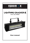
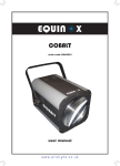
BI-LD016 Instruction Manual
WARNING
FOR YOUR OWN SAFETY, PLEASE READ THIS USER MANUAL CAREFULLY
BEFORE YOUR INITIAL START-UP!
The manufacturer will not accept liability for any resulting damages caused by the
non-observance of this manual or any unauthorized modification to the equipment.
* Never let the power-cable come into contact with other cables. Handle the power-cable
and all mains voltage connections with particular caution!
* Never remove warning or informative labels from the equipment.
* Do not open the equipment and do not modify the equipment.
* Do not connect this equipment to a dimmer-pack.
* Do not switch the equipment on and off in short intervals, as this will reduce the system’s life.
* Only use the equipment indoors.
* Do not expose to flammable sources, liquids or gases.
* Always disconnect the power from the mains when equipment is not in use or before cleaning!
Only handle the power-cable by the plug. Never pull out the plug by pulling the power-cable.
* Make sure that the available voltage is between 110v/240v.
* Make sure that the power-cable is never crimped or damaged. Check the equipment and
the power-cable periodically.
* If the equipment is dropped or damaged, disconnect the mains power supply immediately.
Have a qualified engineer inspect the equipment before operating again.
* If the equipment has been exposed to drastic temperature fluctuation (e.g. after
transportation), do not switch it on immediately. The arising condensation might damage
the equipment. Leave the equipment switched off until it has reached room temperature.
* If your product fails to function correctly, discontinue use immediately. Pack the unit securely
(preferably in the original packing material), and return it to your Prolight dealer for service.
* Only use fuses of same type and rating.
* Repairs, servicing and power connection must only be carried out by a qualified technician.
THIS UNIT CONTAINS NO USER SERVICEABLE PARTS.
* WARRANTY; One year from date of purchase.
CAUTION! TAKE CARE USING THIS
EQUIPMENT!HIGH VOLTAGE-RISK
OF ELECTRIC SHOCK!!
Technical specifications
You should find inside the carton the following items:
1, BI-LD016
2, Power cable
3, Instruction manual
Technical Specifications:
DMX channels: 8
Voltage: AC 110--125V
50--60Hz
72 Ultra bright LED’s (R: 24, G: 24, B:24)
Fuse: 1 Amp
Power Consumption: 20W
Operations:
There are 4 operating modes to choose from:
1, DMX mode
2, Auto Run mode
3, Sound active mode
4, Slave mode
DMX Mode
To select DMX mode, set dipswitch 10 to ON. You can now set the required DMX address using
dipswitches 1 to 9. The start address for this fixture is 0. Please refer to the chart below for DMX
functions.
Auto Run Function Mode
To select auto pattern mode, set all dipswitches to the OFF position. The unit will now cycle
through all it’s built-in patterns. In this mode the LEDs will remain constantly chasing until the
power is turned OFF or the mode is changed.
Sound Active Mode
To select sound active mode set dipswitch 9 to ON. You can now use the sensitivity control on the
back panel to set the required sound input level. With no music present, the LEDs will turn OFF
and will come back ON as soon as the music starts again.
Slave Mode
To select the slave mode set dipswitch 9 to OFF and others to ON. The slave units will now follow
in conjunction with the master unit.
Note: The master unit can be run in any mode for the slave units to follow.
Overview
Back
Features:
1, Hanging bracket
2, DMX in
3, DMX out
4, Dipswitches
5, Power Out
6, Power In
7, Mirophone
8, Sound sensitivity control
9, Fuse
10, Cooling fan
DMX Function Chart
Channel
Value
Function
1
0-255
Tilts top mirror up and down
2
0-255
Tilts bottom right mirror up and down
3
0-255
Tilts bottom left mirror up and down
4
N/A
Not used
0-251
Pattern selector, 1 to 15 (top mirror)
252-255
Blackout (top mirror)
0-251
Pattern selector, 1 to 15 (bottom right mirror)
5
6
7
8
252-255
0-251
252-255
0-255
Blackout (bottom right mirror)
Pattern selector, 1 to 15 (bottom left mirror)
Blackout (bottom left mirror)
Speed control
DMX Set up
DMX-512:
* DMX (Digital Multiplex) is a universal protocol used as a form of communication between
intelligent fixtures and controllers. A DMX controller sends DMX data instructions form the
controller to the fixture. DMX data is sent as serial data that travels from fixture to fixture via the
DATA “IN” and DATA “OUT” XLR terminals located on all DMX fixtures (most controllers only have a
data “out” terminal).
DATA Cable (DMX cable) requirements (for DMX operation):
* The TriScan can be controlled via DMX-512 protocol. The DMX address is set on the
back of the unit. Your unit and your DMX controller require a standard 3-pin XLR connector for
data input/output (figure 1).
Figure 1
Further DMX cables can be purchased
From all good sound and lighting suppliers
or Prolight dealers.
Please quote:
CABL10 – 2M
CABL11 – 5M
CABL12 – 10M
Also remember that DMX cable must be daisy chained and cannot be split.
DMX Set up
Notice:
* Be sure to follow figures 2 & 3 when making your own cables. Do not connect the cable’s shield
conductor to the ground plug or allow the shield conductor to come in contact with the XLR’s outer
casing. Grounding the shield could cause a short circuit and malfunctions.
Special Note: Line termination:
* When longer runs of cable are used, you may need to use a terminator on the last unit to
avoid erratic behaviour.
Termination reduces signal transmission problems
and interferance. it is always advisable to connect a
DMX terminal, (resistance 120 Ohm 1/4 W) between
pin 2 (DMX-) and pin 3 (DMX+) of the last fixture.
Using a cable will reduce the possibilities of malfunctions.
5-Pin XLR DMX Connectors:
* Some manufactures use 5-pin XLR connectors for data transmission in place of 3-pin. 5-Pin
XLR fixtures may be implemented in a 3-pin XLR DMX line. When inserting standard 5-pin
XLR connectors in to a 3-pin line a cable adaptor must be used. The Chart below details the
correct cable conversion.
Dip Switch Reference Chart
DMX Dip Switch Quick Reference Chart
Dip Switch Position
Dip Switch position
DMX Address