1
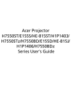
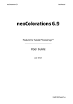
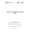
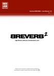
CALIBRATION WIZARD
Version: 8.0.0.21275
Last update: January 2015
neoStampa
1
Index
1. Introduction ……………………………………………………………………………………….………..….
4
1.1 Starting the wizard 8 ………………………………..……..…………………….…………..…
4
2. Print configuration …………………………………………………………….………….…………………
6
2.1 Printer selection ……………………………………………………….…..………..……………
6
2.2 Configuration of the spectrophotometer ………………………………………………..
7
2.3 Action selection ……………………………..……………………………………………………
7
2.4 Check printer and/or profile consistency …………………………………………..…….
8
3. Print parameters ………………………………………………………………………..….…………………
11
3.1 Quality …………………………………………………………………………………………………
11
3.2 Color mode ……………………………………………………….……………………..……………
11
3.2.1 Set color order ……………………….…………………….………………..…………
11
3.2.2 Double ink ……………………………………………………….…………………..….
12
3.2.3 Mask ……………………………………………………….……….…………..…………
13
3.3 Dithering …………………………………..………………………………….………………………
15
3.3.1 Raster settings ………………………………………………..…..………….……….
15
4. Absolute ink limit, Single ink limit and Linearization ……………………………..…………….
17
4.1 Step 1 - Ink limit …………………………………………………….…………….…….…………
17
4.2 Step 2 - Single ink cut……………………………………………………..……….…………….
18
4.3 Step 3 - Linearization ………………….………………..……………………….………..…….
21
5. hueman v2 - Black generation ….………….………………………………..………………..…………
23
5.1 Method ……………………………………..………………………………..…….……..…………..
23
5.2 Patch file ………………………………………….……………………..………….….…………….
24
5.3 Add function ………………………………….…………………………………………….…….…
25
5.4 Print …………………………………………..………………………………..………………………
25
5.5 Rich black …………………………………………………..………………………………..……….
25
6. Advanced settings …………………….…………………………..…………………………….…..………
27
6.1 Revision ………………………….…………..………………………………..………………………
27
6.2 Profiling mode ……………………………………..…………………………….…………………
27
6.3 Balance ……………………………………..………………………………..………….……………
28
6.4 Black start ………………………………….…..……….. ……………………….……..………….
28
6.5 Body (light) ………………………….……………..………………………………..………………
28
6.6 Body (dark) ……………………………………..………….………..………………………………
28
6.7 Ink limit method …………………………………………………..……………………………….
29
6.8 BlackOptimizer ……………………………………..………………………………..…….………
29
6.9 Shadow dot gain ……………………………….……………………………..…………………..
29
7. Printer profiling ……………………………………..………………………………..………..……………..
30
7.1 Select target file …………………………………………………………..………………………
30
7.2 Print ………….………………………………..………………………………..………………………
31
7.3 Measure …….………………………………..………………………………..……………………..
31
7.4 Import data …………………………………………..………………………………..…………….
32
7.5 Export data …………………………..……………..………………………………..….………….
32
7.6 Smoothing amount ……………………….………………………………..……….……………
32
2
7.7 Generating the profile ……………………………………..……………………………………
32
7.8 Add profile to list …………………………………………..………………………………..……
33
7.9 Gamut and quality view …………………….………………..……………….……………….
33
8. Workflow …………………………………….………..………………………………..……………………….
34
8.1 Test print ……………………………………………..………………………………..…………….
35
8.2 Comments ………………………………………..………………………………..………………..
36
8.3 Schema Backup ……………………..………..………………………..…………….…….……..
36
8.4 Finish ……………………………………..…..……….………………………..……………….……
37
3
1/ Introduction
With this Wizard 8 you can print different kind of test charts, in order to control and set ink amounts,
linearization curves and maximum ink limits, as well as printing an ICC target and create an ICC printer
profile.
The very important difference from neoStampa 7 calibration wizard is that this new version offers a
better control of the ink limit -and therefore better dark and light transitions-, and in some cases larger
gamut.
This Wizard 8 also offers the option to check existing calibrations, without having to go through the whole
process of measurements.
In this User Manual you will find descriptions of the options that the Calibration Wizard offers, and
extensive explanations as of various processes and aspects involved in this complex process.
1.1 Starting the Wizard
Access the Calibration Wizard 8 from the Printer Schema Manager, in neoStampa’s 8 upper bar on the
main window.
The Calibration wizard button is at the bottom left corner of the Printer schema manager:
4
The program opens at clicking on the Wizard:
5
2/ Print Configuration
In the first window of the Wizard you are required to introduce the most basic information for the
calibration.
The buttons at the bottom -apart from Configure- allow to move through the different windows of the
Wizard, and to Exit the Calibration, whether saving it or not.
2.1 Printer selection
In the upper part of the window are the settings of the printer you want to make the calibration with.
Hitting the square button with three dots will allow to add a printer to the list of printers that you already
have.
6
2.2 Configuration of the spectrophotometer
At the bottom of the window, as we have seen, there is the Configure button, which will open the
window to set the device you are going to use for measurements:
Depending on the device you use, the options for Transparency, Zebra ruler or UV filter will be activated or
not.
The Color management option in this window allows to select whether to work with the previous
neoStampa 7 profiler, -set by default- or the new neoStampa 8 one.
2.3 Action selection
There are three options in the Action selection field. The two first ones are described following.
The first is to Start a new calibration, in which you need to fill in the information as for Media name, Ink
type and Quality. Inèdit recommends to include all this information, as your schema will be easily
identified. Anyway, the name of the schema can be changed later on.
Legacy mode, when activated, will use older profiling versions of neoStampa.
7
The second option is to Continue and existing calibration. Just open the drop-down list and choose the
one you need, allow to see the already completed calibrations:
2.4 Check printer and/or profile consistency
This function is new in respect to the Calibration wizard 7. This is a very useful tool to check if the profiles
that you have already generated still keep the same quality. However, If you need to change inks, or
media, this re-profiling is not the thing to do as you should make a whole new calibration.
Search for the schema in the drop-down list, and hit Next, on the lower bar. You will access the last
profiling window of the calibration:
Since this process is just a check, the profile that will be generated is based on 152 patches. Proceed now
to Print the target and measure it. As in all Prints in the Wizard, you will be able to configure it before:
8
When the reading is done, you will get the compared DeltaE results.
And if you wish to see all the compared colors, click on the View all results … button:
If the obtained deltaE are larger than desired, you can now proceed to generate a new profile, pressing the
Generate button, and once you have it, Embed the new profile into the schema:
9
Finally press Finish, and a last dialog will pop-up, where you can give a new name to the schema:
10
3/ Print Parameters
Establish color specifications such as for Color mode, Print quality and Dithering in the second window of
the Wizard.
3.1 Quality
Quality is usually printer dependent and is provided by the driver specifications of each printer.
In the “Advanced” button next to it, you can see and change -if necessary- printer specific parameters,
such as single or bi-directional printing, number of passes, etc. Also here, the content of this window is
driver specific.
3.2 Color mode
The Color mode is selected from a drop-down list. The available selection depends on the printer
specifications.
3.2.1 Set color Order
Press the three-dots button on the right of Color mode to set the color order for the selected mode. Apart
from that, you can also set other parameters such as multiple inks or special colors from the window that
pops up:
11
Print:
In case you are not sure what ink order is loaded in you printer, you can print out a chart showing a
number for each printed base color. Certain printers have a special ink order coming from the driver
documentation (e.g. Epson, Mutoh). It is recommended to print out this chart if you are not sure of the
order or if you encounter strange color effects during the calibration process (e.g. Black prints Cyan).
Set color order:
On the left side of the window, set the inks in use according to your machine
specifications or to the previously printed mini chart. There are many inks available in neoStampa RIP, and
make sure you select the correct ones. Be careful when selecting Gray and Light Gray, as the latter can
only be used if Gray is present. Gray is sometimes called Light Black by certain ink suppliers, and Light Gray
would be Light Light Black for those too.
3.2.2 Double Ink
You can place the same ink into different slots multiple times. If you do so, the Double Ink button is
activated and lets you specify the behavior of those inks.
12
Channel: Toggle between the multiple inks. For each ink you can set an individual curve behavior. The
use of multiple inks is basically to make the total color get darker or more saturated. Setting different
behaviors for each channel enables special effects, such as minimizing dithering in lighter areas. A
consideration in this software-based approach of multiple inks lays upon the fact that certain printheads
are more used than others. Finally, the combination of multiple inks, including all the set parameters, are
linearized as one new ink.
We recommend that at least one channel should be linear and that you should NOT change the parameters
after you have linearized the combo.
View curve: It presents the behavior of the curve for the selected ink. Make sure that it looks smooth, if
you want to obtain homogeneous results. You can change the Start, Body and End by increasing or
decreasing the values below.
• Start: This value defines where the ink starts. 25 means that the selected channel will not
print below 25% of original coverage.
• Body: This value defines where the ink starts. You can try different values to evaluate which
ones are the most suited to deliver a smooth shape. 75 is a good value if Start s at 25% and
End at 100%.
• End: This value should usually be set at 100, since the idea is to get darker color. Note,
however, that in some cases you might have too much ink, and you may have to reduce it in the
ink cut procedure, which will be explained further on in this manual.
3.2.3 Mask
If you have special inks loaded, such as a penetration liquid, dilution ink, mask or white inks, you can set
parameters for this in the Mask channel settings window. The Mask ... button becomes available when you
select one of the following inks: Mask, White (background), Dilution ink.
13
Following find explanations for each of the options available in this window:
Get from alpha channel: As the name says, the image to print requires an additional Alpha channel
added to the image, e.g. manually created in Photoshop. The ink then uses the channel information to
print the content. Depending on the printer, the ink will be printed in a separate pass or simultaneously
with the other inks.
Full mask: neoStampa will create a flat color underneath the image whenever a pixel is present (with
Photoshop: always; with Illustrator or CorelDraw: whenever an object contains a color information, such as
white). Note that the full mask generation is only done if the image is in Grayscale, RGB, CMYK or LAB, but
not with multichannel files. So, when printing linearization targets the full mask will not print.
Shadow mask:
neoStampa will create an intelligent grayscale mask under the image information
according to its color intensity and color darkness. Usually, this mode is used when printing white ink, e.g.
for T-shirt printing. Note that the Shadow mask generation is only done if the image is in Grayscale, RGB,
CMYK or LAB, but not with multichannel files. So, when printing linearization targets the shadow mask will
not print, but it will be generated when printing the ICC target.
Fill ink: This method is usually used for penetration liquid or for a fill-up ink, such as dilution inks or
similar. The penetration liquid is provided by several ink suppliers with the idea of helping inks in lower
percentages to penetrate through the textile media. The fill ink method needs specifying an Intensity and
Minimal value explained underneath.
Put ink in white pixels: Usually white pixels do not require a penetration liquid or dilution ink-since the
area is not printed anyway- , which results in ink savings. In certain printing environments (e.g. carpet
printing using Zimmer ChromoJET800) this check-box helps to create a blocking area around the colored
image using dilution ink to prevent colors from bleeding into non-printed areas. Note that “white pixels”
refer to an image information with an object containing no color (with Photoshop: always; with Illustrator
or CorelDraw: whenever an object is found containing a white color).
Intensity: The Fill ink method will fill up with dilution ink, whenever this specified value is not reached by
the absolute amount of other inks in the ink set. So, when you print 10% Cyan+25%Magenta+30%Gray,
the absolute amount of ink will be 65%. In this case, neoStampa will automatically add a 35% of dilution
ink for better penetration.
Minimum value:
Specifying a minimum value for the Fill ink method adds a certain amount to an
absolute ink amount in any case. Scenario: If you set intensity to 100% and the Minimum value to 10%
and the absolute amount of ink of 25% Cyan+35% Magenta+ 75% Gray exceeds the 100% of specified
Intensity, then neoStampa will add another 10% on top of it. This will help the ink to penetrate even more,
but can also cause a certain amount of bleeding if applied too much. This value should be used with care.
14
3.3 Dithering
neoStampa 8 provides different raster methods. Two of them are the most common to use:
Smooth Stochastic (default):
This raster is a matrix-based method that places the dot matrix in the most homogeneous way, and it is
recommended for all types of inkjet printers. It has, however, some drawbacks, specially with n-level
printheads, as the nozzle can suffer from stress.
Diffusion v2
This raster is based on a Smooth Stochastic matrix but adds some error diffusion to the final raster. In
terms of performance, this method puts holes into the regular matrix in order to give time for relaxation to
the nozzle, in order to prevent the previously mentioned stress factor. The raster method is homogeneous
as the first one, but since certain dots are removed, it might be that the dot placement does not look as
“perfect” as with the Smooth Stochastic.
3.3.1 Raster Settings
The option Dithering unfolds a drop-down list:
The button with three dots on the right of the list allows to set different types of dots, which we explain
following:
15
Disable large dot: If you have a delicate media that cannot pick up a lot of ink, disabling the largest dot
(available with 2bit / 3 or more level printheads only!) can help. It can also help if the printhead has
problems firing the large dot, but this is quite a rare scenario. As the name says, the largest dot will not be
produced during rastering. We recommend however not to use this function as reducing ink in the perchannel ink cut provides more control.
Disable small dot: In some printing environment using certain printheads, the small dot never reaches
the media since a combination of a small dot with high printing carrier movement speed, and/or
electrostatic charge (e.g. using polyester fibre), deviates the dot so much that it is literally blown away.
This can cause a lot of residual ink in the environment ,and the dust is placed anywhere, an effect that is
certainly not wanted. Using this function switches off the usage of the smallest dots (available with 2bit/3
or more level printheads only!).
Only for black ink: If this box is selected in combination with “Disable small dot”, then the smallest dot is
only omitted in the Black channel(s).
Smoothness:
This value becomes available when working with Diffusion v2 raster method in
combination with an n-Bit / n-Level printhead. The smoothness defines the amount of error introduced to
the matrix raster to avoid stress from the nozzles when firing full-time (mentioned in Dithering Part 1). A
smoothness of 10 means that Diffusion v2 does not have any error diffusion (=Smooth Stochastic). By
decreasing this value, dots are removed from the regular matrix and the n-Levels of variable drop
technology are diffused into each other. A value of 6-9 delivers a good balance between quality and
stress-reduction to printheads with variable dot technology. If you go lower than this value, there can be
too much noise in the result and the print-out will go grainy. We recommend a value of 7 if you encounter
such a firing stress problem. Note that changing to Diffusion v2 or changing the amount of Smoothness
requires re-linearizing the printing conditions.
Dot multiplier: This value must be left at “1”. We recommend NOT to change it.
16
4/Absolute Ink Limit, Single Ink Limit and
Linearization
To complete this window of the Wizard there are three very important steps that need to be done, and
they need to follow an order:
4.1 Step 1 - Ink Limit
In Ink Limit you are able to print up to a 300% of ink, to find the best absolute ink limit for your media on
the test file.
Test file print to cut the absolute ink limit:
Before the actual print, a window opens with a preview of the charts, where you can adjust some
parameters (ink channel, print direction, position, orientation and page setup):
17
To evaluate the test chart in textile media, make sure that it is washed and steamed before. Then, where
it starts showing bleeding, proceed to cut the inks.
4.2 Step 2 - Single Ink Cut
In Single Ink Cut you are able to cut single ink limit. Therefore you need to print a CMYK plus light inks test
chart, with gradient of 0%-100%. Ink cut limit just for the main inks, no lights, as shown in screenshot
above (Channel/color).
Test file print to cut the single ink limit:
18
Once again, before the actual print and measurement, a window opens with a preview of the chart, where
you can adjust parameters (ink channel, print direction, position, orientation, page setup): Linearization
for full ink set, CMYK+cmk+g, as seen in screenshot below:
When the above parameters are set, press Ok to print the test file.
Then press the Measure button and connect the spectrophotometer. Follow the instructions for the
specific device you are working with.
Notice that the Calibration Wizard 8 offers the possibility to get 3 measurements for each print. This is
useful when for example the media is rough, and we want to get much precise results. The Wizard will
produce average values from the 2 or 3 measurements.
Notice also that the data for this measurements -and of each reading- can be Exported, with the bottom
left button on the window, and, if necessary, they can also be Imported.
19
When you finish the reading, the Densities and Ink cut dialog will pop-up. The Wizard will perform an
automatic ink cut, based on the values obtained. The new values are based on 100% of ink:
The dE method can be applied in the Linearization or in the Ink cut. You can choose so just below the
curves chart:
In Light inks transition you can pre-set the best ink transition.
Below the Light inks preset, the Advanced button will take to another window where more settings can
be applied for the light inks:
20
4.3 Step 3 - Linearization
In Linearization, you are able to see the performance of CMYK ink set with light ink set in linearization
curves. Therefore, you need to print a CMYK test chart with gradient of 0%-100%. If you are not using
light inks, please skip this step:
Print Test file:
For the third time, the window with the chart preview and adjustments options pops-up:
21
After printing the test file, proceed to connect the spectrophotometer, as you did before. Then start
reading the lines according to given specifications:
When you finish the reading, the Linearization performance will pop-up. The Wizard will perform an
automatic ink cut, based on the values obtained.
22
5/ hueman V2 - Black Generation
In this new window you get to the part to define the Black generation of your printer’s calibration. This
process allows to determine which combination of inks provide the best black, as well as it prevents
dithering of the black ink in the light areas, in case you don’t have any gray ink in combination.
5.1 Method
hueman v2 Black generation provides 3 methods to generate the black ink:
• Default (Black only):
This method is recommended if you have a very good, strong black ink in your printer and if you also have a
gray ink (=light black) that prevents dithering from the black ink in light areas. In this case the black
generation will be black only.
23
• Black Addition:
This method is recommended if a combination of inks is better than your pure black ink only, and if you
also have a gray ink (=light black) in the printer to prevent dithering from the black in light areas. Here, the
black generation will add the defined values of the additional inks to improve the overall darkness of the
result. You can use the “Print..” button to determine whether a combination of colors including black is
better than the black ink only.
• Gray Component Replacement (GCR):
This method is recommended if a combination of inks is better than your pure black ink and if you don’t
have a gray ink (=light black) in your printer. With this method CW8 will replace light areas of black with a
combination of CMY inks, to visually minimize the dithering from the black ink. Be aware that such a GCR
can be critical since the light fastness of C, M and Y are not always the same and that after a certain time
one of the inks might fade faster than others resulting in a non-neutral behavior of gray areas (e.g.
outdoor flag printing).
5.2 Patch file
In order to evaluate whether a combination of inks is better than your pure black ink, you can use the
“Print..” button to print out a chart for visual analysis. You can select one of the charts in the list. For most
printers, the BlackAdd_CMYK.psd (or the smaller A4-sheet-fitting BlackAdd_cmyk_A4.psd) will be
enough. If you have additional process colors, such as Orange, Blue or Red (not light inks!), you can select
the according patch file.
Example: If you have loaded Cyan, Magenta, Yellow, Black, Gray, Orange, Blue, Red in your printer, chose
the BlackAdd_CMYK+3. psd (or _small.psd). Since Gray is a light ink, do not count it as +1 ink.
24
5.3 Add function
You can add individual charts to print if you would like to test another set of combinations. Be aware that
the chart MUST be in multichannel format so you can arrange the channel order in the “Print..” window. We
recommend that you put at least 4 spot channels and name then with Cyan, Magenta, Yellow, and Black,
so that CW8 can auto-assign them to the proper ink channel.
Note that the multichannel file is a special color mode in Photoshop and may not contain CMYK or RGB
color channels on top. Save them in .psd format.
5.4 Print
Print the selected chart for visual analysis. In digital textile printing you should steam and wash the chart
since you want to see the final result (as with all charts except with the ink limit charts in most scenarios).
The default charts contain different combinations of black with the other process colors. In the center of
each patch you’ll find the 100% pure black ink. Around the center is 100% black plus the combination of
inks with the values noted aside. If you really find a black that is better outside than inside (better=darker
and/or more neutral, etc.) you can use these values to fill them into the “Rich black” fields.
5.5 Rich black
In the example above, the red circled patch has a better black outside than in the center. We will use K100,
C60,M60, Y60 for the “Rich black” fields for either Black Addition or GCR.
Note: Do not use extreme combinations, such as K100, C90, M90, Y0, since you might encounter other
problems that are not seen in this chart (e.g. light fastness, steaming stability, etc.). We recommend to use
a combination containing all values, such as K100, C60, M60, Y30 or K100, C30, M30, Y30, for stability
purposes.
25
Of course, only select a “Rich black” if the combination is really better than the black only, since you will
increase the ink amount, leading to higher production costs.
Fill the determined values into the fields. You can only use “Rich black” in combination with Black Addition
or Gray Component Replacement method.
26
6/ Advanced settings
The advanced settings of black generation are provided format experienced users only. Usually, using the
regular black generation window will be sufficient to get a high-quality profile. Advanced settings allow to
fine-tweak or control certain printing environments, but it can also lead to wrong results if not used
properly. Proceed with care and use the default settings, whenever possible.
Here is the window that opens when selecting Advanced settings:
6.1 Revision
By default, CW8 will automatically select the latest color separation technology in the revision list. The
latest revision usually delivers the best result for each specific ink combination. We recommend not to
change the revision unless specifically instructed by your distributor or by Inèdit.
6.2 Profiling mode
The default profiling mode for neoStampa is RGB profiling. The profiler included in CW8 (optional license)
that creates the ICC profile will only work if RGB is selected. In addition to this, all configuration parameters
in the black generation will only be available with RGB profiling mode.
27
The CMYK profiling can be used if the ICC profile is created with an external profiler that can create ICC
CMYK printer profiles. The black generation using CMYK profiling can be defined in the external profiler
usually.
6.3 Balance
The “Balance” parameter allows to increase or decrease individual inks to balance the black generation
combination using Black Addition or GCR. Since the profiling process will correct irregularities in the
balance between inks, the “Balance” option is not really required, and the values should be left at 1.0 In
very rare occasions, a certain ink may be much stronger (or weaker), in relation to others, and can be
corrected here. The resulting curve will be displayed in the Black generation preview, on the right of the
window.
6.4 Black start
The curve control area allows to specify certain conditions on the curve, such as Black start, Body (light)
and Body (dark). The Black start sets the start position of the black ink to the defined value.
The default value for Black start using Black Addition is 33%. It means that the additional colors to achieve
a richer black will start to enter after 33%, and will reach the specified value at 100%. Below 33% only
black ink (including gray) will be used.
The default value for Black start using GCR is 10%. This means that below 10% of 2626black generation,
no black ink will be present, but instead it will be replaced with a combination of C, M, and Y inks. This is to
prevent dithering of the black ink if no gray ink (=light black inks) is present in the ink set.
6.5 Body (light)
The Body -light- parameter shapes the curve in the lower area of black generation. The ideal value is
experimental, but should result in a smooth and regular total curve shape, which can be seen in the Black
generation preview.
The default value for Body -light- using Black Addition is 83. The default value fro Body -light- using GCR is
33.
6.6 Body (dark)
The Body -dark- parameter shapes the curve in the upper area of black generation. Also here, the ideal
value is experimental and should result in a totally smooth behavior of the final curve as seen in the Black
generation preview.
28
The default value for Body -dark- using Black Addition is 100. The default value for Body (dark) using GCR
is 66.
6.7 Ink limit method
neoStampa includes two methods for ink limiting:
Smooth: The default method provides an intelligent ink limiting without clipping behavior in heavy ink
load areas. It optimizes the ink amount in extreme areas to provide smoother behavior of gradients but
sacrifices 2-3% of gamut.
Clip: The clip method just cuts down the exceeding ink to the defined value. Although the gamut might be
2-3% larger in these extreme areas, it is possible that gradients in very dark areas are not as smooth as
with the above method.
6.8 BlackOptimizer ®
This function improves the gamut behavior in colorful areas when moving towards saturated, dark colors.
Since -specially in digital textile printing-, the regular GCR method doesn’t always directly make a color
darker, but turns it duller and sometimes even lighter, an intelligent analysis of color-to-dark is required,
to improve the combination of colors in the black generation. BlackOptimizer does this analysis based on
whether a color is already dark, and therefore uses less GCR to get darker. It is recommended to leave this
button always on. If you encounter some dithering from color-to-dark (e.g. if the black ink starts too
early), it might help to switch the function off, although it might make the printer gamut less linear.
6.9 Shadow dot gain
A dot gain can be added to improve overprinting of colors, also in darker areas. An insufficient saturation in
dark areas is sometimes caused by an intermediate ink limit behavior, which causes a bump between
absolute ink limit (2-mix-colors) and the relative ink limit set in the RIP (e.g. 240%). A regular dot gain is
usually applied to all colors, but from the CIELab point of view, the linearity is not given anymore. The
Shadow dot gain parameter adds a dot gain only where is it required; in already saturated colors, to
counteract the bump effect. The default value of 15% is a good balance between improving the bump
effect and laying down too much ink, but mainly depends on how heavy the colors have been linearized.
The Early black improves the gradient
and linearity from dark-saturated to dark-unsaturated color,
affecting the black ink directly in normal cases, and should be switched on by default. Switch it off only if
you experience strong jumps in dark-unsaturated areas from the black ink or a rich black combination.
29
7/ Printer profiling
This is the step in the calibration process where the ICC profile is generated. After completing the hueman
v2 black generation window, you will get to the printer profiling one, when hitting next. Remember that
this option is only activated if you have purchased the license to generate ICC profiles, so, if you don’t have
it you will not access this last window.
7.1 Select target file
In order to print a target for your spectrophotometer, select from the drop-down list the appropriate
target: Small/Medium/Large/Very large/Custom. For a high-quality profile, you should print at least 1500
patches for paper prints, and 2250 for textile prints.
30
Then choose the device from the drop-down list:
7.2 Print
After you have selected the right target, use the “Print…” button to print out the target file on your media.
As with all charts, you have to steam and wash it, or have it dry for a couple of minutes (paper printing).
Configure the Print of the target first:
7.3 Measure
You are now ready to measure the target. Make sure you select the same target file that you have
previously printed, and click on the “Measure...” button to open the measurement dialog and to connect
with the spectrophotometer.
31
When you finish reading the target, hit Ok to close the measurement dialog and you will see that the
“Generate...” button becomes selectable.
7.4 Import data
If you wish to Import a previously stored measurement, you can use the Import button to do so. Note that
the CW8 will check whether the data content corresponds to the correct reference file (e.g. amount of
patches, etc.).
7.5 Export data
You may need to Export data for example if you’d like to create an ICC profile with an external application
such as i1Profiler. CW8 creates CGATS, which are measurement files that are compatible with most ICC
profiling software. Select the i1Profiler format if you want to generate the ICC profile with i1Profiler
software.
7.6 Smoothing amount
With this option you can specify a certain amount to smooth out error measurements, although much of it
is avoided by choosing to do three measurements of each test file, as the CW8 has newly incorporated.
Broadly speaking, the more you smooth a profile the less precise this will be, so smoothing should apply
only if the global precision of an ICC profile is maintained, and the most important aim is to achieve
smoother gradients in printing.
The options for smoothing are, in general terms: None should be used when measurements are good, as
with paper; Few can be selected for stable readings on dense, low-structured textiles; Normal would
apply with unstable measurements on structured textiles; finally, High is only to be selected for
extremely structured textiles, like towels. This latter is not recommended to use, as it implies heavy
smoothing.
7.7 Generating the profile
After you have measured the target, the “Generate...”button will become available. Select first from all the
above parameters and then click on this button to generate de ICC RGB printer profile.
A window will pop up to ask how you’d like to name the profile. It is recommended to give the same name
to the profile that you gave to the complete calibration, to avoid confusion. You can also specify where
32
you’d like to save the generated profile; typically, in the desktop since you can easily distribute if from
there, or within your profile folder.
7.8 Add profile to list
Once you have your ICC profile generated, this will appear on the profile list automatically.
7.9 Gamut and quality view
View the linearization and the projection of the profile in the gamut viewer.
If you make a click in the gamut area another window will pop up, showing a color picker with the printable
colors. Here you can scroll through the bar to detect error messages or smoothness issues coming from
irregular measurements or misreadings.
33
8/ Workflow
We have reached the last window of the Calibration.
In the upper part of the window, the Workflow options can be used to define some initial parameters.
Color Preset offers two methods: the Standard mode, which uses the Perceptual mode and thus provides
more realistic colors, and ColorBoost, which uses saturated colors and renders brighter colors.
Mirroring is usually used for transfer. In this window you have the option of applying Full page mirroring,
which will obviously change the whole page.
Input defaults displays a new window:
34
By default, Input ICC profiles is not activated, as changing them may completely change the colors you
will print.
The same goes for Proofing. This consists of obtaining from our printer the results which would be
obtained using another printing system. Please refer to point 5.2 of neoStampa’s manual to understand
the main rendering intents offered.
Also, beware in the above window if you are going to use the Design orientation and mirroring
options, because if you have already selected Full page mirroring in the previous window, these buttons
will now double the effect.
Full page mirroring and Input defaults provide the same setting options given in the Printer schema
manager, in the Advanced tap.
8.1 Test print
With the Test print option you are able to choose a test image and check the profile and print quality.
With the “plus” button you will choose the file you need from your computer. Once selected, this will be
included in the drop-down list.To test the image you like, just press Print.
35
8.2 Comments
Quite self-explanatory, an empty area to include Comments belonging to the calibration is available.
Those will be seen when you open the Advanced tap of the Printer schema manager:
8.3 Schemas Backup
In the Printer schema manager (window above), at the bottom, there are two buttons for you to save
copies of the schemas created, generated by the Backup button.
You can name and save your copies, which will be stored as zip files:
Whenever you want to use any of those copies, press Restore and selected it from the given list:
36
8.4 Finish
The last step will be to “Finish...” the calibration by clicking on this button. You will be prompted to give it a
final name to complete the calibration.
Once the Wizard is closed, if you want to use the schema created, you will need to open the Printer
Schema manager and click on “Browse... “ to locate the calibration:
If no other routes have been expressly selected, the usual path is /neoStampa 8/Color/Printername/
Calibration name. After that, your new calibration will automatically become available in the schemas list,
in the Printer schema manager.
We hope this manual has been useful to you. If you think the contents can be improved in any way,
you can send your suggestions to [email protected]
In our web www.inedit.com you will find further support materials such as video tutorials, apart from
all the information of the programs and solutions of Inèdit.
37