1
BFBS TechniSat User Guide
System
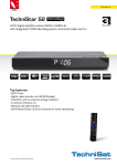
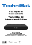
This user guide is intended for use with BFBS/TechniStar set top
boxes (STBs) of the style illustrated above. If you have a different
type of TechniSat unit, some information may be relevant, but it is
preferable to refer to the correct manual for your unit.
The Pace and Humax branded units are significantly different in their
menu structures.
Page 1 of 15
23-8-12
BFBS STB
The BFBS STB has a front panel providing two operational controls
with one at the extreme left being a power ON/STANDBY button.
The other control replicates the left/right/up/down arrows and OK
button of the remote control. Both these controls are also available
on the remote control and this is generally the preferable way to
operate the STB.
Towards the right end is a flap covering the slot for the Conditional
Access Module (CAM). The CAM holds a Viewing Card.
The CAM and/or Viewing Card are normally both pushed fully home
and are shown withdrawn here to show which way round they go.
Cards and CAMS should never be removed unless instructed by the
support team at BFBS. If the STB has been transported, open the
flap to ensure card and CAM are still both pushed fully home. Cards
are removed by pulling them outwards, taking care not to bend them
or touch the exposed contact pads. The CAM can be removed by
pressing the lever at the right of the CAM slot then once it is
released, pulling it straight outwards.
Page 2 of 15
23-8-12
Units are normally supplied fully configured prior to shipment, or they
may be setup by the local satellite technician making the installation.
In most cases, they will require no further settings changes unless
some other form of television set with a different aspect ratio or form
of connection is to be used.
If contacting BFBS for support purposes, it is important to identify
your STB as being the TechniStar S1 version. You will also be asked
for Viewing Card number (the 11 digit number above the bar code)
and also the CAM identifier which is 14 characters.
Do not attempt to use the Viewing Card/CAM in any unit except the
one for which it was supplied.
Connections
Mains
As a minimum, set top box systems
need connecting to a mains supply
and a television set. The STB has a
separate mains power unit which is
supplied with alternative power input
adapters. One adapter is for UK style
“13 amp” sockets and the other for
European type 2 pin plugs. The mains
supply requires one, or other adapter
to be fitted as shown here. First,
engage the end away from the power
outlet cable end of the mains power
unit, then pivot it down until it locks in
place.
Take care to store the unused adapter in case the STB is ever
relocated to an area where it is needed. To remove one adapter to fit
another, slide the OPEN button towards the power outlet cable end
of the mains power unit. It will then be released.
Page 3 of 15
23-8-12
Signal
Television
Connections
230 V supply
Optional connections
Mains adapter
Speaker system
Digital i/p amp
If a box needs to be reconnected to a television set having different
parameters, use the STB remote control and press the MENU
button, found below and left from the arrow/OK controls. Refer to the
set maker’s specification for full details but the most likely
parameters that may need changing are the form of connection
(HDMI or SCART) and the aspect ratio. 4:3 is a traditional style TV
and ‘widescreen’ sets are 16:9.
When television sets with an HDMI connection are available, this is
the preferred form of link. SCART and RCA phono connections
provide alternative links.
Page 4 of 15
23-8-12
Changing output options
Although output signals, may be present, it is
important that the set top box (STB) is correctly
configured for the type of connections being
used.
To select between HDMI and SCART outputs;
Switch on STB and television and select
on the television set whichever input the
STB is connected to.
Press the ‘MENU’ button on the remote
control.
Use the arrow ‘UP’ and/or ‘DOWN’
function to go to ‘SETTINGS then press
OK.
In the settings menu, use the ‘UP’ / ‘DOWN’ / ‘OK’ controls
to go to and select ‘PICTURE SETTINGS’.
Page 5 of 15
23-8-12
To change the output to be used, use the remote to reach
the required line. Then press the ‘LEFT’ / ‘RIGHT’ arrows to
change between SCART and HDMI.
If using a SCART connection, the SCART mode should
normally be set to CVBS if your television supports this. If
necessary change to RGB mode.
A similar process with the arrow controls allows changes to
be made to match the aspect ratio of your television. For
traditional (older) televisions it should be set to be 4:3.
Newer ‘widescreen’ types should have it set to 16:9.
Once the required changes are entered, press the “BACK”
button. Depending what has been changed, you may be
asked to confirm that the changes should be stored by
pressing the ‘OK’ button.
Page 6 of 15
23-8-12
Card enabling
BFBS television broadcasts are encrypted to prevent programmes
being watched by non-authorised viewers. When a Viewing
Card/CAM is issued, the card details are submitted for the card to be
enabled. It can take up to two hours for the card to begin working
Until that happens, you cannot watch TV programmes and the
screen will show this “not authorised” message:
During this time, the RADIO mode can be used and allows you to
check that the audio connections are all OK.
Page 7 of 15
23-8-12
Pin number
BFBS services carry a wide range of material and two types of
Viewing Cards are available. If you have a ‘FAMILY’ card certain
programme classifications cannot be viewed. ‘ADULT’ cards can
view all programmes but a personal identifier number (PIN) must be
entered for programme classified as “adult”.
Users should change this to be their own PIN as follows
Press the ‘MENU’ button on the remote control.
Use the arrow ‘UP’ and/or ‘DOWN’ function to go to
‘SETTINGS then press OK.
With the arrow controls, navigate to ‘PATENTAL CONTROL’
and then to ‘CHANGE PIN’.
You will be asked to enter the current PIN which as supplied
has a default of 0000.
Enter a new number you will remember.
If you select a programme with a 15 or greater rating, the STB will
prompt you to enter the PIN.
Page 8 of 15
23-8-12
Other commonly used options
The set top box is designed to be as energy efficient as possible. To
minimise power consumption the ‘quick start’ feature is normally
disabled and gives improved efficiency when the STB is left in
standby mode.
To enable the Quickstart mode, switch on STB and television.
Press the ‘MENU’ button on the remote control.
Use the arrow ‘UP’ and/or ‘DOWN’ function to go to
‘SETTINGS then press OK.
Next use the remote’s arrow controls to navigate to ‘BASIC
SETTINGS’ then on to the ‘QUICKSTART’ line.
Press OK then use the ‘LEFT’ / ‘RIGHT’ arrows to enable or
disable the feature.
A further power-saving feature is the ‘Auto Standby’ feature that is
accessed on the same menu page. The factory default is for the unit
to go into standby mode three hours after the last button press on
the box or remote control. Alternative time-out periods, or for it to be
disabled, can also be selected.
Page 9 of 15
23-8-12
Switching on
To use the STB system, it is necessary to ensure that the television
has either the HDMI or SCART input selected, depending which has
been connected. This often involves the use of an ‘INPUT’ or
‘SOURCE’ menu that should be documented in the instructions
provided by the TV set manufacturer.
When it has been powered down, or switched to standby, the STB
requires a minute or so to re-boot. After a short time the BFBS on
screen message is displayed for a few seconds.
Once this message clears, the decryption system begins to enable
BFBS reception.
Page 10 of 15
23-8-12
Selecting TV and radio channels
To use the BFBS DTH system, it is necessary to ensure that the
television has either the HDMI or SCART input selected, depending
which connection has been used for the set top box. If it is the first
time the set top box has been used, it will default to the TV channel,
BFBS1. Otherwise, the STB will resume reception of whichever
channel was being received when it was last used.
To go to another channel for which you know the channel number,
pressing the appropriate number button will take you directly to that
channel. To change between radio and TV modes, press the
‘TV/RADIO’ button once. Radio channels can also be selected by
their channel number. A powerful feature of the BFBS system is the
Electronic Programme Guide, the ‘EPG’. This is opened by pressing
‘EPG button on the remote control.
This opens in the EPG – CHANNEL LIST mode and shows all the
BFBS services that are enabled in your STB. The number of
channels will vary, depending on your location.
The colour buttons allow the displayed time window to be scrolled in
appropriate increments. Buttons 1 to 7 allow different day’s
programmes to be checked.
Page 11 of 15
23-8-12
A number of other display options are selfexplanatory, though it is important to note
that the recorder features mentioned in
some menus beneath the RED button are
not yet implemented in this version of the
STB and no support can yet be offered
over their future capabilities.
Scrolling to a particular channel then
pressing the GREEN button opens a full
listing for all the programmes on that
channel. Other menu options are
designed to be intuitive, using on-screen
prompts.
To close the EPG, press the ‘BACK’
button.
Page 12 of 15
23-8-12
Care of the system
It is important to ensure that the line of site from all parts of the dish
towards the horizon remains clear of objects. Someone walking in
front of the dish, let alone a vehicle parking there, will cause loss of
signal.
Although always mounted securely, ground
placed dishes should never be handled in any
way as this can easily cause misalignment.
Protective measures should be taken to keep
the necessary area free from all forms of traffic,
including pedestrians.
Set top boxes are the property of SSVC / BFBS
and all possible precautions should be taken to
prevent accidental damage. A small television
set may be placed on top, but ensure not all of
the ventilation holes are obstructed.
Fault finding
Whilst all equipment may sometimes suffer failures, the most
common cause of apparent failure is user error. If you have
established that everything is connected and switched in ways that
have worked previously, begin a logical check of symptoms to allow
a useful fault report to be made.
The error message “NO INPUT SIGNAL’ can mean there is a fault
anywhere in the system between the dish and the rear connection to
your set top box. If you are in a building complex with other STB
users taking signals from the same dish, check with others to
establish if your STB is the only one affected or if the problem is
more widespread. Wide-scale loss of service may be due to the dish
having been mechanically disturbed or to the distribution amplifiers
linked directly to the dish having faults, or being switched off!
When signals are being received but have become prone to
interruptions, “mosaicing” or other degradations, the STB has a
facility to check the strength and quality.
Page 13 of 15
23-8-12
To use this signal check:
Press the ‘MENU’ button on the remote control.
Use the arrow ‘UP’ and/or ‘DOWN’ function to go to
‘CHANNEL SEARCH’ and press OK. Then scroll to
‘TRANSPONDER’.
Depending on your location, different satellites, with other technical
parameters may be shown on your screen. The signal level is the
significant reading and quality values in some cases may appear low
though this does not necessarily indicate a fault condition.
Page 14 of 15
23-8-12
Technical support
Once a detailed fault description is available, it can be sent by email
to:
[email protected] or by phoning
mil (9) 529 82100 or
+44 1494 878100
Further support help is found at:
www.bfbs.com/tvhelp
Be sure always to give details of the Viewing Card number. This is
the one occasion to carefully remove the card prior to an instruction
from the BFBS support team.
Comments on this user guide
This is not intended to be a full user manual, describing every
feature of the BFBS TechniStar model of TechniSat box. The many
menus are largely self evident and intuitive. However if you feel there
are areas requiring update, please forward suggestions to the
Technical Support contact details above.
Page 15 of 15
23-8-12