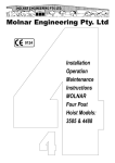
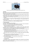
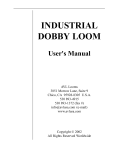
1
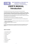
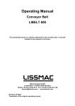
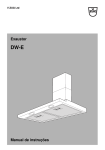
OPERATION MANUAL
Floor Cutter
FS UNI-CUT
This manual should be available to your service personnel at all times to
ensure correct and careful handling of the machine.
Maschinenbau u. Diamantwerkzeuge GmbH
Mechanical Engineering – Diamond Tools
Lanzstraße 4 - D-88410 Bad Wurzach
Telefon +49 (0) 75 64/3 07-0 - Fax + 49 (0) 75 64/3 07-5 00
[email protected] - www.lissmac.com
State:2007/02
1
Preface
This operating manual should make it easier to learn to acquaint yourself with the
machine and all its features.
The operating manual contains important information on safe, efficient and
technically correct operation. Following the instructions helps prevent accidents,
unnecessary repair costs and down time which enhances the machine’s reliability
and service life.
The operating manual is yet to be supplemented with instructions pertaining to
national laws concerning accident prevention and environmental protection.
The operating manual must always be accessible on the machine.
Every person working on the machine must read and follow the instructions in the
operating manual. This includes the following areas:
• Operation, including setting-up, troubleshooting during operation, disposal of
waste products, product care, disposal of lubrication and auxiliary products.
• Servicing (maintenance, inspection, repair) and/or
• Transport
In addition to the operating manual and in compliance with all binding national and
local regulations concerning accident prevention, the general technical regulations
for safe and correct operation must also be adhered to.
Table of Contents
1. General Safety Precautions
2. Description of Machine
3. Commissioning
4. Transport
5. Operation
6. Maintenance
7. Spare parts list
8. Annex
10. Guarantee
2
1. General Safety Precautions
1.1 Warning Labels and Symbols used in this Manual
Danger ! Not following the instructions can results in serious injuries or
even death.
Caution!
Note!
Not following the instructions can, under certain conditions, result
in injuries.
Not following the instructions can result in damage to the
machine or other equipment.
1.2 General Safe Operating Procedures
1.2.1 The machine has been manufactured in keeping with the most recent
technology and the recognized safety rules. Nevertheless there may be some
risk of a hazard to life and limb of the user or third persons or impairments of
the machine and other real assets respectively.
1.2.2 Use the machine only in good working conditions and follow all procedures
concerning correct and safe operation, as outlined in the manual! This applies
specifically to malfunctions that can jeopardize safety! Take immediate action
to eliminate troubles!
1.2.3 This floor cutter is intended for cutting concrete or asphalt exclusively. The
cutting of wood, plastic material or metal (except concrete reinforcements) is
not permitted!
Any other utilisation of this floor cutter is considered inadmissible. The
manufacturer/supplier is not liable for any damage caused by undue
application.
Correct operation also requires following instructions in the operating manual
as well as adhering to inspection and maintenance procedures.
1.3 Organizational measures
1.3.1 Always keep the operating manual close to the machine and easily
accessible!
1.3.2 Follow all laws and regulations concerning accident prevention and
environmental compliance listed in the supplement to this operating manual.
3
1.3.3 Any personnel working on the machine must read this operating manual,
especially this chapter on safety precautions, prior to beginning. Learning on
the job is too late! This especially applies to persons who work occasionally on
the machine (like setup or maintenance crews).
1.3.4 Perform regular spot checks to ensure that personnel are doing their jobs in a
safe and conscientious manner and that they are adhering to the instructions
in the operating manual.
1.3.5 Use personal protective equipment whenever necessary or when required by
regulations!
1.3.6 Pay attention to all safety and danger warning labels located on the machine!
1.3.7 Keep all safety and danger warning labels in/on the machine completely
legible!
1.3.8 Immediately stop the machine and notify parties in charge when performing
safety-related changes on the machine or its operation or becoming aware of
any trouble of this kind!
1.3.9 Make no alterations and do not add componentry or rebuild the machine
without permission from the manufacturer!
1.3.10 Use only original spare parts!
1.3.11 Perform all scheduled inspections as needed, or use the scheduled intervals
as outlined in the operating manual!
1.3.12 For carrying out maintenance work, adequate workshop equipment is
indispensable.
1.4 Qualifications for Selecting Operators; Fundamental Responsibilities
1.4.1 Only personnel of proven reliability are allowed to operated the machine.
Observe legal minimum age requirements!
1.4.2 Use only qualified and trained personnel. Clearly define staff responsibilities
concerning operation of machine, setup, maintenance, and repair works!
1.4.3 Ensure that the floor cutter is handled only by persons appointed to do so!
1.4.4 Define machine operator’s responsibility – also in respect to road traffic
regulations – and his ability to object to instructions not in compliance with the
safety regulations!
4
1.4.5 Apprentices, new employees, or personnel receiving general training must be
supervised at all times by an experienced operator while working on the
machine!
1.4.6 Any work at the electrical equipment of the floor cutter must be carried out by
a qualified electrician only or a trained person under the supervision of a
qualified electrician, in accordance with the rules and standards for
electronics.
1.5 Safety Notice to Certain Operation Times
1.5.1 Normal Operation
1.5.1.1 Do not perform procedures that may present a safety risk!
1.5.1.2 Take steps to ensure the machine is used only when it is in a safe,
operational state!
1.5.1.3 Machine must be examined for externally visible damage at least once per
shift. Report any changes (including performance) to the appropriate parties
in charge at once. If necessary, immediately stop and secure the machine!
1.5.1.4 Immediately stop and secure the machine when malfunctioning! Promptly fix
the problem!
1.5.1.5 Prior to starting work, familiarize yourself with the locality and its
environment.The environment may include obstacles within the working and
traffic area, safe floor load, necessary protection of the site towards public
traffic areas, first aid in case of accident.
1.5.2 Using the Floor Cutter for Extracurricular Jobs, Maintenance Procedures,
Troubleshooting; Waste Disposal
1.5.2.1 Follow the instructions in the operating manual when adjusting, maintaining
and inspecting componentry and performing scheduled work. This includes
the replacement of parts! Only qualified personnel are allowed to perform
these activities.
1.5.2.2 Notify operators of any maintenance or additional work prior to performing!
Appoint a supervisor!
1.5.2.3 When the machine is completely turned off for maintenance or repair work, it
must be safeguarded against an unexpected restart!
5
1.5.2.4 Prior to cleaning the machine with water or by steam jet (high pressure
steam jet) or with other cleansing agents, cover and seal all openings into
which, due to safety or functional reasons, water/steam/cleansing agent may
not penetrate. Particularly protect endangered electric motors and switches.
1.5.2.5 Completely remove all covers/tape after cleaning!
1.5.2.6 Tighten any loose screws after performing maintenance or repair work!
1.5.2.7 If the protective devices on the machine need to be removed for setting up,
maintenance or repair work, they must be reassembled immediately
afterwards and tested for their safety features to ensure safe operation!
1.5.2.8 Dispose of lubrication and auxiliary devices as well as spare parts in a safe
and environmentally friendly manner.
1.6 Precautions for Special Types of Danger
1.6.1 Electrical Power
1.6.1.1 Use only original fuses with the electrical current for which they were
designed! Immediately turn off the machine when encountering power supply
problems!
1.6.1.2 Any work on electrical equipment must be performed by a qualified
electrician only or by trained persons under the supervision of a qualified
electrician, in compliance with the regulations for electrical engineering.
1.6.1.3 Regularly inspect/check the machine’s electrical condition. Problems, such
as loose connections (e.g. damaged cables) must be immediately repaired.
1.6.2 Dust
1.6.2.1 Observe all national regulations and standards when working in small
spaces!
1.6.3 Noise
1.6.3.1 Wear officially prescribed personal ear protection!
6
1.7 Transport
1.7.1
Ensure that your hoisting gear and load suspension devices have adequate
carrying capacity.
1.7.2
Have an experienced coordinator direct the lifting process!
1.7.3
Lift the machines using only approved lifting equipment as per the
instructions given in the operating manual (striking points for loading
procedures)!
1.7.4
Use only a vehicle providing sufficient carrying capacity for transporting the
machine!
1.7.5
Secure the load. Use the appropriate striking points!
1.7.6
Turn off the power even when moving the machine only a small distance!
Before restarting, ensure the machine is securely connected!
1.7.7
Always follow the instructions in the operating manual when restarting!
2. Description of Machine Componentry
2.1 Component Overview
Pos. 1
Steering Rod
Pos. 2
Operation Desk
Pos. 3
Driverseat
Pos. 5
Diesel tank
Pos. 6
Saw blade protection cap
Pos. 7
Motor frame
Pos. 8
Saw head with hydraulic motor, guidance elements, and saw blade
protection cap
Pos. 9
Travelling gear
Pos. 10
Hydraulic tank
Pos. 11
Striking points
Content: diesel engine, steering, hydraulic pump
Content: steering, gear
7
8
2.2 Protection Devices
Pos. 6
Saw blade protection cap
2.3. Technical Data
Max. cut depth
Max. saw blade diameter
Saw blade holder
Performance (kW/HP)
Fuel
Tank content
Regular cutting motion
Rapid cutting motion
Saw blade speed, infinitely variable (electronic)
Raising of saw blade
Lowering of saw blade
Hydraulic tank
Weight including sludge extractor
Dimensions
FS UNI-CUT
630 mm
1500 mm
35 mm
98 / 133
Diesel
90 l
0-22 m/min.
0-60 m/min.
700 – 2500 RPM
Hydraulic motor
infinitely variable
50 l
2030 kg
2700/1100/1800 mm
2.4. Accessories
- Saw blade protection cap ∅ 1200/1500 mm
- Sludge extraction
2.5. Perceived noise level of FS UNI-CUT
Guaranteed sound level
= 105 dB(A)
WARNING!
Ear muffs must be worn if a 90 dB(A) noise level is exceeded!
Sound ranging method in accordance with ISO 3744, 3862 and Regulation
2000/14/EG.
9
3. Commissioning
3.1 Operation desk
Prior to starting the floor cutter, the operator has to make himself familiar with the
machine.
Meaning of the symbols:
12. Water pump ON - OFF
13. Hydraulic oil temperature is too high (green light) / hydraulic oil level (red light) is
too low (light must not burn during operation)
14. Current supply (light burns during operation)
15. Preheating (light burns during start-up)
∗ required if outside temperatures are low
16. Emergency cut-off
17. Battery charging control (light must not burn during operation)
18. Motor oil pressure (light must not burn during operation)
19. Air filter (light must not burn during operation)
∗ change dirty cartridge (see 6.1)
20. Working hours counting device
21. Cooling water temperature
22. Sludge extraction ON - OFF
23. Saw blade change-over switch
0 = Off
1 = left
2 = right
24. Control lever for direction of motion and cutting speed (must always be in middle
position at the start)
Control lever forward
=
forward motion
Control lever backward
=
reverse motion
Button pressed down
=
rapid cutting motion
Button up
=
regular cutting motion
Attention! The rate of speed is set by control knob (pos. 25)
26. Gas lever for diesel engine
10
27. Vertical adjustment of saw protection cap
Lever forward
=
saw cap up
Lever backward
=
saw cap down
Lever in middle
=
saw cap stops
Atttention This lever also controls the feed motion of the saw cap.
Wide deflection
= increased feed motion
28. Lever
Lever forward
Lever backward
Lever in middle
Attention
=
=
=
saw blade up
saw blade down
saw blade stops
This control knob (pos. 29) controls the rate of speed of the saw
blade.
Wide deflection
=
increased feed motion
30. Working pressure during sawing process
31. Saw blade speed control
32. Saw blade speed
33. Change of cutting direction
- When reversing the cutting direction, the steering has also to be changed
34. Electronic feed motion ON - OFF
35. Socket for cooling water controller
- red light burning
=
insufficient cooling water
36. Ignition lock
37. Connection for programming device
38. Sockets
3.2 Connections / lubrication and auxiliary devices
- When delivered, the floor cutter is filled with HD-oil and diesel fuel. Anyway,
these should be checked.
∗ HD-oil level gauge (pos. 47)
∗ Fuel-level gauge (pos. 48)
∗ Couple cooling water hose (pos. 42)
11
12
3.3 Assembly of saw blade
- All switches on the operation desk must be in position “0”
- Start motor with ignition key (pos. 36)en
- Move saw blade drive to highest position
∗ lever pos. 28
∗ control knob pos. 29
Danger!
- Switch off ignition (pos. 21)
- Remove eye bolts (pos. 39+40)
- Uncouple extraction hose and undo saw blade cover
- Remove all screws (pos. 41)
- Remove pressure disk and insert saw blade
Attention!
* Clean flange surfaces
* Arrows indicating direction of rotation (arrow on the blade)
and protection cap must coincide (synchronous saws)
-
Mount the pressure disk and screws (pos. 41)
- Assemble saw blade cover and put back extraction hose shoe
13
14
3.4 Preparations for start
- Put the floor cutter in position
∗ Steering rod disk and saw blade (or rear side marker) are positioned above
the cutting line
*Couple water hose at pos. 42 or at extraction point
- Open water plugs (pos. 42)
- Set saw blade speed control knob (pos. 31) to “0”
- Select sense of rotation of saw blade (pos. 23) - Put diesel engine gas lever (pos. 26) in „full throttle“ position
- Adjust speed with control knob (pos. 31) – see table below
∅ mm
45m/sec.
(concrete)
55m/sec.
(asphalt)
400 500
600
700
800
900 1000 1100 1200 1500
215
0
263
0
1720
1430
1230
1080
960
860
780
720
580
2100
1750
1500
1310
1170
1050
960
880
700
∅ mm
45m/sec.
(Concrete)
55m/sec.
(asphalt)
- Switch on water pump (pos. 12)
- Set feed motion control knob to “zero” (pos. 29)
- Put lever (pos. 28) in „down“ position
- Slowly initiate the dipping motion with the feed motion control knob - until the
saw blade starts cutting
Attention!
Is the saw blade provided with sufficient cooling water?
- Put the cut depth indicator (pos. 43) to “zero”
- Dip the saw blade to desired cut depth (mm) (indicator pos. 43)
∗ Control knob (pos. 29)
∗ Lever (pos. 28)
- Set control knob (pos. 25) to “zero”
- Push the steering lever (pos. 24) forward (button is not pressed down)
- Slowly initiate feed motion with control knob (pos. 25)
* If required, switch on electronic control system (pos. 34) – see 5.2
3.5 Regular / rapid cutting mode
3.5.1 Regular cutting motion
- Steering lever (pos. 24) is in middle position
- Put control knob (pos. 25) to “zero”
- Start diesel engine by ignition key (pos. 36)
- Actuate gas lever (pos. 26)
∗ Define desired maximum speed
- Push steering lever (pos. 24) into desired direction of motion
- Start movement by control knob (pos. 25)
3.5.2 Rapid cutting motion
- Proceed as indicated under 4.1.1 „normal cutting motion”
- Simultaneously, button on steering lever (pos. 24) pressed down
15
16
4. Transport
Displacement by crane
- Has the crane enough carrying capacity?
- Fix quadruple suspension gear with adequate carrying capacity using jack rings
provided (pos. 11)
- Lift carefully
Danger!
- Do not allow any persons to loiter under suspended loads at
any time!
- Always keep an eye on the floor cutter!
5. Operation
5.1 Regular cutting operation
- Start preparations (see 3.4)
5.2 Cutting with electronically controlled feed function
(applicable for reinforced concrete only)
- Start electronical control (pos. 34)
- Push steering lever (pos. 24) in direction of motion
- Raise speed by turning control knob (pos. 25)
Attention! If the rate of speed is selected too high, there is a risk of
considerable fluctuations of the feed motion due to electronical
control
17
18
5.3 Cooling water
- Make sure that the saw blade is supplied with sufficient cooling water
∗ Use only clean water!
∗ Do not buckle hose!
5.4 Choice of saw blade
See the “Lissmac Diamond Tools“ brochure. Only use saw blades recommended by
the manufacturer.
5.5 Change from right to left cutting
- Stop diesel engine (pos. 36)
- Dismount steering rod lifter (pos. 44)
- Remove hexagon screws (pos. 45)
- Lift steering rod and suspend in rope
- Pivot the sawing unit to middle position
- Mount HD cylinder from pos. 46 to opposite side (introduce from above first)
- Pivot the whole sawing unit to left side
- Fix the sawing unit with straining screws again (pos. 45)
- Reassemble steering rod (pos. 1) and steering rod lifter (pos. 44) at left side
- Fix the driver seat at the other side
- Pivot operation desk accordingly
- Do not forget to change the sense of rotation (pos. 23) of the saw blade
Attention: If the saw blade was already fixed, this needs to be turned as well
(see 3.3)
19
6. Maintenance
6.1 Maintenance
firstly
change hydraulic oil
change hydraulic filter
check hydraulic oil level
lubricator nipples
Saw blade guiding element
Check cooling water filter
Check hoses and screwed
connections of hydraulic
system for tightness/damage
daily
weekly
monthlyh
50 h
50 h
yearly
X
X
warning light
ON
every „x“
operating hours
500 h
500 h
X
X
X
X
20 h
X
Diesel engine see „Deutz“ operating manual
Please observe the operating instruction of the engine manufacturer (you will find it attached to each new machine).
Especially observe the safety and maintenance instructions.
20
6.2 Lubrications and auxiliary devices
- Diesel engine see Deutz operating manual
- Lubricator nipple
∗ Energrease LS2 BP
7. Spare Parts / Wearing Parts
Designation
Lissmac Item No. Deutz Ident. No.
Engine oil filter
206599
01174418
Fuel filter
206598
01181245
Filter / water separator
207502
01319822
Air filter cartridge
204638
26510342
Safety cartridge (air filter)
204640
26510343
Hydraulic filter (Argo)
204554
V3.0923-08
Engine oil 15W40 (without filter change) approx. 8.5 litres
Engine oil 15W40 (with filter change) approx. 10 litres
Hydraulic oil BP-Bartran HV68 approx. 55 litres
Driving wheel
207676
Hydraulic motor with brake
206529
Hydraulic motor without brake
206530
Starter battery
402115
Silencer
691678
Driver seat
206553
Wheel / steering roller / rod
207344
Water pump
207405
Water plug 3/4"
280011
HD level indicator
203730
Throttle linkage, complete
681118
HD manometer 0-600 bar
206566
HD mini-measuring hose
206567
Rotary shaft seal 80x100x7
206550
Conical nipple V-Seal
207168
Seal bushing
628178
O-ring 42x2
201550
Wearing plate / saw blade
628132
Sealing pack for HD engine
207728
Sealing pack for drive gear
681262
Guiding element saw blade
(Ø500/628143)-(Ø1000/628241)protection S-green
(Ø1200/628250)
Wearing plates / saw protection
(Ø500/628140)-(Ø1000/628247)cap
(Ø1200/628252)
Wearing plates / extraction hose
(Ø500/628208)-(Ø1000/628256)shoe
(Ø1200/628267)
21
10. Guarantee
The guarantee time for this machine is 12 months. Guarantee for the following
wearing parts will be given only when the wearing is not due to working
conditions.
Wearing parts are parts which are subject to wear and tear in working conditions due
to intended use of the machine. The time of wearing is not defineable in a uniform
way, it depends on their application intensity. The wearing parts of each specific
machine have to be attended, adjusted and, if necessary, exchanged in accordance
with the user’s manual of the manufacturer.
For wearing due to working conditions, no warranty claims will be accepted.
•
•
•
•
•
•
•
•
•
•
•
•
•
•
•
•
•
•
•
•
•
•
•
•
•
•
•
•
•
•
•
Advance and driving elements as tooth racks, toothed wheels, pinions, spindles,
spindle nuts, spindle bearings, ropes, chains, chain wheels, belts
Gaskets and washers, cables, hoses, collars, plugs, ccouplings and switches for
pneumatic and hydraulic systems, water, electricity, fuel
Guidance elements like guiding joints, guiding bushes, guiding rails, rolls,
bearings, antislipping devices
Gripping fixtures of quick-disconnecting systems
Flushing head seals
Gliding and roller bearings which are not running in an oil-bath
Rotary shaft nipples and sealing elements
Friction and overload clutches, brake gears
Graphite brushes, collectors
Easily removable ring collars
Potentiometers and manual control elements
Fuses and lamps
Lubrication and auxiliary devices
Fixing materials as plugs, anchors, nuts and bolts
Bowden wires
Lamellars
Membranes
Spart plugs, glow plugs
Parts of reversing starter, as start by rope, start by handle, start by roll, start by
spring
Sealing brushes, packing rubber, splash guard rags
Filters of all types
Driving-, deflection rollers and roller linings
Protection elements for rope lays
Running and driving wheels
Water pumps
Transport rollers for cutting materials
Drilling-, parting-off and cutting tools
Conveyor belt
Rubber strippers
Needled felt protection
Energy accumulation units
22
LISSMAC Maschinenbau und Diamantwerkzeuge GmbH
EEC Declaration of Conformity
LISSMAC Floor Cutter FS Uni-Cut
•
Manufacturer LISSMAC Maschinenbau und
Diamantwerkzeuge GmbH
Lanzstr. 4
D - 88410 Bad Wurzach
•
Storage of the technical documents by:
Anton Hess (Assistant to the technical director)
LISSMAC Maschinenbau und
Diamantwerkzeuge GmbH
Lanzstr. 4
D-88410 Bad Wurzach
•
Description of machine:
Floor cutter FS Uni-Cut
Floor cutter with 93 kW diesel engine
Cut depth 480 mm
•
Applied procedure of conformity evaluation
Internal manufacturing control
(RL 2000/14/EG Annex V)
•
Measured sound level:
104 dB
•
Guaranteed sound level:
105 dB
•
EC Directives observed:
EC Machine Directive 98/37/EEC,
Noise Directive 2000/14/EEC
EC Low Voltage Directive 73/23 EEC changed by 93/68 EEC
EC Electromagnetic Compatibility Directive 89/336/EEC, changed by
98/68/EEC
EN 12100, EN 13862, EN 60204-1
EN 294, EN ISO 3744
Authorized person legally responsible:
LISSMAC
Maschinenbau und Diamantwerkzeuge GmbH
Gewerbepark West – Lanstrasse 4
88410 Bad Wurzach
Tel.: (0 75 64) 3 07-0, Fax: (0 75 64) 3 07-5 00
Mail: [email protected] – www.lissmac.com
________________________________________
ppa. Josef Weiland
(Technical Director)
23
24
25
26
27
28
29
30
31
32