1
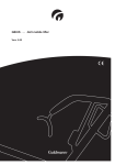
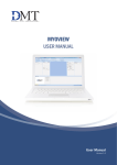
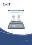
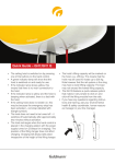
GB/US . . . . GH2 HD Twin lifting modules Vers. 1.00 GH2 HD Twin lifting modules Item numbers: 120001 - x023 1.00. . . . . . . . . Purpose and use. . . . . . . . . . . . . . . . . . . . . . . . . . . . . . . . . . . . . . . . . . . . . . 3 1.01. . . . . . . . . Manufacturer. . . . . . . . . . . . . . . . . . . . . . . . . . . . . . . . . . . . . . . . . . . . . . . . . . 3 1.02. . . . . . . . . Purpose. . . . . . . . . . . . . . . . . . . . . . . . . . . . . . . . . . . . . . . . . . . . . . . . . . . . . . 3 1.03. . . . . . . . . Important/warnings . . . . . . . . . . . . . . . . . . . . . . . . . . . . . . . . . . . . . . . . . . . . . 3 1.04. . . . . . . . . Load limit for the GH2 system. . . . . . . . . . . . . . . . . . . . . . . . . . . . . . . . . . . . . 4 1.05. . . . . . . . . Unpacking and preparation. . . . . . . . . . . . . . . . . . . . . . . . . . . . . . . . . . . . . . . 4 1.06. . . . . . . . . Assembly before use. . . . . . . . . . . . . . . . . . . . . . . . . . . . . . . . . . . . . . . . . . . . 5 1.07. . . . . . . . . Lifting sling. . . . . . . . . . . . . . . . . . . . . . . . . . . . . . . . . . . . . . . . . . . . . . . . . . . . 6 1.08. . . . . . . . . Power supply. . . . . . . . . . . . . . . . . . . . . . . . . . . . . . . . . . . . . . . . . . . . . . . . . . 7 2.00. . . . . . . . . Description of functions. . . . . . . . . . . . . . . . . . . . . . . . . . . . . . . . . . . . . . . . 8 2.01. . . . . . . . . Pictograms. . . . . . . . . . . . . . . . . . . . . . . . . . . . . . . . . . . . . . . . . . . . . . . . . . . . 8 2.02. . . . . . . . . Indicator lights. . . . . . . . . . . . . . . . . . . . . . . . . . . . . . . . . . . . . . . . . . . . . . . . . 9 2.03. . . . . . . . . Operation. . . . . . . . . . . . . . . . . . . . . . . . . . . . . . . . . . . . . . . . . . . . . . . . . . . . . 9 2.04. . . . . . . . . Safety features. . . . . . . . . . . . . . . . . . . . . . . . . . . . . . . . . . . . . . . . . . . . . . . . 10 2.05. . . . . . . . . Charging/connection . . . . . . . . . . . . . . . . . . . . . . . . . . . . . . . . . . . . . . . . . . . . 11 2.06. . . . . . . . . Accessories. . . . . . . . . . . . . . . . . . . . . . . . . . . . . . . . . . . . . . . . . . . . . . . . . . 12 3.00. . . . . . . . . Transport . . . . . . . . . . . . . . . . . . . . . . . . . . . . . . . . . . . . . . . . . . . . . . . . . . . 13 4.00. . . . . . . . . Maintenance and storage. . . . . . . . . . . . . . . . . . . . . . . . . . . . . . . . . . . . . . 14 4.01. . . . . . . . . Cleaning. . . . . . . . . . . . . . . . . . . . . . . . . . . . . . . . . . . . . . . . . . . . . . . . . . . . . 14 4.02. . . . . . . . . Storage . . . . . . . . . . . . . . . . . . . . . . . . . . . . . . . . . . . . . . . . . . . . . . . . . . . . . 14 4.03. . . . . . . . . How is corrosion prevented/avoided?. . . . . . . . . . . . . . . . . . . . . . . . . . . . . . 14 4.04. . . . . . . . . Owner’s daily maintenance obligations. . . . . . . . . . . . . . . . . . . . . . . . . . . . . 14 4.05 . . . . . . . . Disposal of GH2 incl. batteries . . . . . . . . . . . . . . . . . . . . . . . . . . . . . . . . . . . 14 5.00. . . . . . . . . Service and lifetime. . . . . . . . . . . . . . . . . . . . . . . . . . . . . . . . . . . . . . . . . . . 15 5.01. . . . . . . . . Lifetime . . . . . . . . . . . . . . . . . . . . . . . . . . . . . . . . . . . . . . . . . . . . . . . . . . . . . 15 5.02. . . . . . . . . Service inspection. . . . . . . . . . . . . . . . . . . . . . . . . . . . . . . . . . . . . . . . . . . . . 15 5.03. . . . . . . . . Troubleshooting. . . . . . . . . . . . . . . . . . . . . . . . . . . . . . . . . . . . . . . . . . . . . . . 16 6.00. . . . . . . . . Technical specifications. . . . . . . . . . . . . . . . . . . . . . . . . . . . . . . . . . . . . . . 17 A.. . . . . . . . . . . Users guide . . . . . . . . . . . . . . . . . . . . . . . . . . . . . . . . . . . . . . . . . . . . . . . . . 20 B.. . . . . . . . . . . WARRANTIES. . . . . . . . . . . . . . . . . . . . . . . . . . . . . . . . . . . . . . . . . . . . . . . . 20 © Guldmann GB/US-1364/04/08 • # 900692 7.00. . . . . . . . . EC declaration of conformity. . . . . . . . . . . . . . . . . . . . . . . . . . . . . . . . . . . 19 1.00 Purpose and use 1.01 Manufacturer V. Guldmann A/S Graham Bells Vej 21-23A DK-8200 Aarhus N Tel. + 45 8741 3100 Fax + 45 8741 3131 1.02 Purpose GH2 HD Twin lifting modules (hereinafter called GH2) are ceiling-mounted lifting systems which cover the requirements for heavy and special lifting at hospitals, nursing homes, institutions, swimming pools, riding schools and in private homes. • • • • • • • • © Guldmann GB/US-1364/04/08 • # 900692 1.03 • • • • • • • • Prerequisites The use of GH2 is subject to the following prerequisites: Before installing the rail system a written declaration from a building expert is needed. It must be documented that the ceiling construction can bear and is suitable for the installation of the GH2 rail system. The aid/working tool is used by trained staff. The training offered by Guldmann to all customer groups on the purchase of a ceiling/mounted lifter has been undertaken. The helper is aware of the user’s well-being when the product is being used. The product may be used only with rail systems which have been tested and approved according to Guldmann’s instructions. Only fitters who have been approved by Guldmann should install and test the rail systems. The product is used with the Guldmann lifting sling or other suitable sling Point 2.06. The product is used with a Guldmann hoist or with other suitable hoists. Point 2.06. Important/warnings Please read the user manual before you start using GH2. Do not exceed GH2’s recommended load of 455 kg /1000 lbs. GH2 must only be used to lift people. The red emergency stop cords must be adjusted so that they are within reach of the user. GH2 must not be used where there is a risk of it being splashed with water. If a defect appears during use of GH2, it must be taken out of service and Guldmann’s Service Team must be contacted to repair it. If GH2 is used in places where the distance between the rail system and the floor is more than three metres, the lifting strap must be extended with an extension strap. GH2 is controlled by a micro processor PCB which can be damaged by static electricity if touched without the necessary precautions. See Point 1.08. The electronics must only be serviced by trained service engineers. 1.04 Load limit for the GH2 system See the labels on the products for maximum load limits. The product, e.g. hoist, which is labelled with the lowest load limit, determines the maximum load limit for the entire system. The maximum load limit must not be exceeded. Please note that the load limit may change if different products are used on a daily basis, e.g. lifting sling, hoist. 1.05 Unpacking and preparation Visual check of GH2 If GH2 is thought to be damaged upon receipt, it must not be used before it has been checked and approved by a qualified person or the Guldmann Service Team has checked and approved GH2. The contents of the box 1. GH2 2. Hand control 3. Connector bar 4. Connecting cable 5. Transformer/charger 6. Manual 7. Label for rail system 8. 2 charging stations (for DC charger) 1 2 © Guldmann GB/US-1364/04/08 • # 900692 3 1.06 Assembly before use Installing the rail system Change compared to installing other Guldmann rail systems! Check that the rail system is installed with the following maximum distances between fittings: • • • GH2 HD Twin DC Mini rail =1250 mm / 50” Maxi rail = 3500 mm / 140” Jumbo rail = 5250 mm / 210” • GH2 HD Twin AC Midi rail =2500 mm / 100” 4 brackets must be used when fitting rail systems with standard curves. Important! GH2 HD Twin must not be used in rail systems with switch tracks, turntables and combi-locks. © Guldmann GB/US-1364/04/08 • # 900692 Installing GH2 1. Place the lifting modules end to end so that the connector bar can be installed. 2. Install the connector bar between the lifting modules with the nuts and bolts supplied. 3. Place GH2 in the rail system. 4. Install the connecting cable between the lifting modules. 5. Extend the red emergency cord and stop so that they are always within reach of the user. 6. Fit the four-pole plug in accordance with the enclosed guide. Precautions for ESD protection apply. See Point 1.08. 7. Reset the emergency stop to connect power to the product. This is done by pressing the contact arm to which red emergency stop cord is attached against the product until it clicks. 8. Charge GH2 as shown in Section 2.05. 9. GH2 is now ready for use with the Guldmann rail system. Lifting sling A Guldmann lifting sling with 4-6 lifting straps, which are designed for use with hooks with diameters down to 8 mm / 0.3”, must be used. Slings made by other manufacturers Guldmann shall not be liable for faults or accidents that occur as a result of using slings made by other manufacturers. In case of doubt concerning the selection or use of a lifting sling, please contact your supplier. Guldmann shall not be liable for faults or accidents due to incorrect use of the lifting sling, or for reasons of inadequate attention on the part of the helper or user. Working with GH2 As GH2 makes no particular demands on space or power consumption and runs smoothly in the rail system, it is only necessary to pay attention to the user’s functional level and the helper’s technique. The user should be lifted just above the underlying surface and moved at this height. © Guldmann GB/US-1364/04/08 • # 900692 1.07 1.08 Power supply GH2 is equipped with batteries that require regular recharging. The power supply for the charging and battery charging point must be connected by a qualified engineer or by the Guldmann Service Team. Always use the transformer/charger supplied. AC power supply When the power is supplied via the rails (MIDI rail), the AC transformer Guldmann type DTS-2420, item no. 937000 must be used. For connection please refer to the installation guide. If AC power supply is used (MIDI rail) the hoist will after use be constantly recharged throughout the length of the rail. DC power supply When the power is supplied via 2 charging stations, a DC charger, one for each hoist, of the type Mascot 2240, item no. 937030, must be used. For connection please refer to the installation guide. If DC power (MINI, MAXI and JUMBO rails) is used, the hoist must after use be placed in the charging station for recharging. The charging station is marked with on the rail. © Guldmann GB/US-1364/04/08 • # 900692 Safety concerning static electricity (ESD) Service engineers and installers must use an ESD safety package when working with electronic components. This package consists of a mat, a ground wire and a bracelet. The engineer/installer connects the mat to a grounding point, e.g. a radiator or a water pipe. He must then put on the bracelet and connect it to the mat. If the engineer is using a ladder, it is important that the mat is placed on the step on which he is standing. If it is not possible to find a grounding point, the mat and the bracelet must be used as a minimum. Only then is it permitted to work with the PCB or components where it is possible to come into contact with the PCB. 2.00 Description of functions Information panel on GH2 seen from the floor. Pictograms Charging indicator Emergency lowering Emergency stop Example of serial number label No. 120001-1001-2005 max 250 kg/ 550 lbs 24V AC/DC. FUSE 5AF. 75 VA. ED15% IP20 V. Guldmann A/S, Graham Bells Vej 21-23A DK-8200 Århus N, Tel. +45 8741 3100, www.guldmann.com © Guldmann GB/US-1364/04/08 • # 900692 2.01 CE labelling Type B in accordance with EN 60601-1 Read the user guide before use Permissible operation time e.g. 3 minutes’ work and 20 minutes’ break Must not be disposed of as standard household waste, but must be recycled 2.02 Indicator lights Colours and functions are described below: Green Permanent Flashing Off : The product is active : The product is discharged and requires recharging : The product is inactive Yellow Permanent : Charging indicator - indicates that there is a connection between the hoist and charger/transformer 2.03 Operation Manual operation GH2 switches on automatically when the hand control is pressed. GH2 will switch off automatically after approx. 10 minutes if not activated. © Guldmann GB/US-1364/04/08 • # 900692 1. 2. 3. 4. Lifting Lowering Weight adjustment Weight adjustment 1 4 3 2 Caution The strap must be loaded with a weight corresponding to Guldmann’s lifting hanger for GH2’s lifting/lowering function to work. Transport/running in the rail system GH2 is pushed manually forwards in the rail system by the helper. GH2 must not be exposed to extreme cold/heat. E.g. do not run a cold hoist into a hot bathroom, etc. 2.04 Safety features Warning! Emergency stop and emergency lowering should only be used in emergencies. In the unlikely event that it should be necessary t o use the safety functions, the fault must be found and remedied before GH2 is used again. Please contact your supplier. Re EMC If electromagnetic or other interference is experienced between this product and other products, they must not be used together. • • Strap cut-out The red cord has the following functions: One pull: Emergency stop is activated. Two pulls: Emergency lowering is activated (requires a continued light pull). Emergency stop If GH2 does not stop/react to the hand control when GH2 is in use, pull the red cord lightly and all functions except emergency lowering are deactivated. When the emergency stop is activated, GH2 will not function. The emergency stop must be manually pressed before GH2 is again ready for use. After deactivating the emergency stop, the hand control is activated twice: first to reset the PCB second to switch on the hoist 10 © Guldmann GB/US-1364/04/08 • # 900692 • • Emergency lowering If GH2 fails, the electrical emergency lowering is used to lower the user safely. The emergency lowering system is operated by a constant pull on the red cord which is used for emergency stop. When the red cord is not continuously pulled, emergency lowering will be replaced by emergency stop. It will therefore not be possible to activate GH2 in any other way. Key to labels: Type B In accordance with EN 60601-1. Warning Read the user manual/technical documentation before use, cleaning or servicing. Description of strap cut-out Overloading, irregular pulling and/or a twisted lifting strap will cause the strap cut-out to activate and GH2 to cut out. If the yellow label on the strap is visible, the full recommended load must not be lifted. 2.05 Charging/connection When GH2 is not in use, it should be parked in the charging station. This maintains the batteries and ensures long battery life. © Guldmann GB/US-1364/04/08 • # 900692 When GH2 is charging, the yellow charging indicator on GH2’s information plate will be on. The indicator switches off and on during battery charging. The light only indicates that the connection between GH2 and the trans former/charger is correct. The green circle of lamps on the bottom of GH2 flashes if the charge level is too low – GH2 can then only carry out a limited number of lifts and must be recharged. Place GH2 in the charging station marked with the battery symbol on the rail for recharging. When GH2 is fitted in the MIDI rail, charging can take place throughout the length of the rail. 11 Accessories Guldmann hoist Obtain a special brochure from your distributor, manufacturer or at www.guldmann.com Extension strap The extension strap is used where the distance between the lower edge of the rails and the floor exceeds 3000 mm /120”. For example, if the distance is 3500 mm /140” a 500 mm / 20” extension strap can be purchased from your supplier. Cross lifting hanger The cross lifting hanger can be used in two ways depending on what kind of hoist is being used. Lifting sling with divided leg straps: Place the lifting sling with the wide side facing the user. Hook the back straps on the hoist onto the hooks closest to the user and the leg straps to the hooks farthest away from the user. Lifting sling with undivided leg straps (Sit-On sling): It is an advantage to position the lifting sling with the narrow side facing the user. Hook the back straps on the hoist onto the hooks closest to the user and the leg straps to the hooks farthest away from the user. Horizontal lifter, foldable The horizontal lifter is a lifting device which is used together with a hoist and rail systems to move people in a horizontal position. It can be stored completely or partially folded in order to minimise space requirements, or it can hang ready to use in the hoist. The horizontal lifter may be used only for horizontal relocation of people lying on a level, horizontal surface. The person must be lying on a Guldmann sling or on another suitable sling. A level surface can be, for example, a bed, a stretcher or the floor. Batteries Battery Guldmann type FG20401 item no. 933015. Charger Charger type Mascot 2240 item no. 937030. Transformer Transformer Guldmann type DTS-2420 item no. 937000. 12 © Guldmann GB/US-1364/04/08 • # 900692 2.06 3.00 Transport Guldmann recommends that GH2 is transported or stored in its original packaging. Key to symbols on the GH2 packaging: -10 14 40°C 104°F 30 70% 700 1060hPa © Guldmann GB/US-1364/04/08 • # 900692 GH2 should be stored: – at temperatures between -10 and +40°C – at a relative humidity of between 30 and 70% – at an air pressure of between 700 and 1060hPa 13 4.00 Maintenance and storage 4.01 Cleaning Clean GH2 with a damp cloth and ordinary detergent. Do not use strong acids, bases or alcohol to clean GH2. No autoclave must be used to clean GH2. 4.02 Storage GH2 must be stored in a dry room with a relative humidity that does not exceed 70%. GH2 should be stored with the emergency stop activated to discharge power from the batteries. For long-term storage the 4-pole plug with the wire colours white, black, red and yellow must be removed. 4.03 How is corrosion prevented/avoided? When GH2 s mainly used in an aggressive environment, e.g. swimming pool, etc., it must be ordered with a special surface coating to prevent corrosion. 4.04 Owner’s daily maintenance obligations Check the sling and the sling straps for wear and tear and damage before the products are used. Do not use the sling if it is damaged or defective. Do not use GH2 if the lifting strap is damaged or defective. Contact your supplier and order a new lifting sling or a replacement for the lifting strap. Replacement of the lifting strap must be carried out by the Guldmann Service Team or by a qualified service engineer in accordance with Guldmann’s instructions. 4.05 Disposal of GH2 incl. batteries Comply with the local and national regulations on environmentally correct recycling. Batteries must always be handed into an approved recycling point. 14 © Guldmann GB/US-1364/04/08 • # 900692 Precautions for ESD protection apply. See Point 1.08. 5.00 Service and lifetime 5.01 Lifetime GH2 has an expected life of 15 years on condition that service inspections are complied with as set out in Point 5.02. Replacement of components Replacing batteries, PCB and fuses must be carried out by a qualified service engineer or by the Guldmann Service Team. 5.02 Service inspection According to the international standard EN/ISO 10535 “Hoist for the transfer of disabled persons – Requirements and test methods” a safety inspection of the hoist must be performed at least one a year. The GH2 must be inspected by a qualified fitter or by the Guldmann Service Team. The service inspection includes a written report specifying what has been inspected and replaced. Worn or defective components must be replaced by new components from Guldmann. Spare parts drawings and documentation can be ordered from the manufacturer or the distributor. 1. Visual inspection of the hoist • Check for wear, irregularities or other types of damage to the hoist 2. Testing the hoist as though in normal use • Check all functions of the product with and without load as described in section 2 • Check that the emergency stop functions • Check that the emergency lowering device functions • Check that the green indicator lamp lights up when the hoist is activated • Check that the yellow charging indicator lights up when the batteries are recharging © Guldmann GB/US-1364/04/08 • # 900692 3. Remove cover/screen 4. • • • • • • Checking the electrical state of the hoist Check batteries for: • Input voltage • Output voltage Check electrical functions and signals Check the wiring circuit for faults or defects Check the cable lead-ins Check the power supply, plugs, etc. Check the electrical safety of the product according to IEC 60601-1/1988 15 5. • • • • • • Checking the mechanical state of the hoist Clean the hoist to remove dirt and other impurities Inspect and evaluate vital components Replace defective and worn components Check and tighten all moving parts Lubricate the hoist Where applicable, treat the surface with silicone oil 6. Replace cover/screen 7. Go through the checkpoints under item 2 again to make sure that . everything functions 8. Have new problems arisen or been found under item 7? • If new problems have arisen, return to item 3 • If there are no new problems, the inspection is completed 9. When a service inspection including service work or exchange of . components has taken place, the final check must comprise a weight test with the product’s nominal load 5.03 Troubleshooting • • • Does GH2 not respond to the hand control’s keys? Check that the emergency stop is not activated Check that the product has power supply Contact the Guldmann Service Team The hand control may be defective 16 © Guldmann GB/US-1364/04/08 • # 900692 Is the green light on GH2 flashing when it is recharging? • Check to see if the yellow charging indicator lights up when GH2 has been run into the charging position • Check to see if the power is switched on • Contact the Guldmann Service Team 6.00 Technical specifications A G H F C D E B K L I J © Guldmann GB/US-1364/04/08 • # 900692 A . . . . . . . . . . . . . . . . . . . . . . . . . . . . . . . . . . . . . . . . . . 770 mm . . . . . . . . 30½” B . . . . . . . . . . . . . . . . . . . . . . . . . . . . . . . . . . . . . . . . . 300 mm . . . . . . . . . 12” C . . . . . . . . . . . . . . . . . . . . . . . . . . . . . . . . . . . . . . . . . 148 mm . . . . . . . . . . 6” D . . . . . . . . . . . . . . . . . . . . . . . . . . . . . . . . . . . . . . . . . 160 mm . . . . . . . . . 6½” E, min. . . . . . . . . . . . . . . . . . . . . . . . . . . . . . . . . . . . . . 242 mm . . . . . . . . . 9½” F, min. . . . . . . . . . . . . . . . . . . . . . . . . . . . . . . . . . . . . . 382 mm . . . . . . . . . 15” G . . . . . . . . . . . . . . . . . . . . . . . . . . . . . . . . . . . . . . . . . 295 mm . . . . . . . . 11½” H . . . . . . . . . . . . . . . . . . . . . . . . . . . . . . . . . . . . 692 - 2692 mm . . . . 27-107½” I . . . . . . . . . . . . . . . . . . . . . . . . . . . . . . . . . . . . . . . . . . 620 mm . . . . . . . . 24½” J . . . . . . . . . . . . . . . . . . . . . . . . . . . . . . . . . . . . . . . . . . 790 mm . . . . . . . . 31½” K . . . . . . . . . . . . . . . . . . . . . . . . . . . . . . . . . . . . . . . . . . 490 mm . . . . . . . . 19½” L . . . . . . . . . . . . . . . . . . . . . . . . . . . . . . . . . . . . . . . . . . 473 mm . . . . . . . . 18½” Angling of connector bar . . . . . . . . . . . . . . . . . . . . . . . . . ± 12° . . . . . . . ± 12° Depth of lifting unit . . . . . . . . . . . . . . . . . . . . . . . . . . . 197 mm . . . . . . . . . . 8” 17 Lifting capacity with cross hanger . . . . . . . . . . . . . . . . . . . . . . . . max. 455 kg . . . . 1000 lbs. Lifting capacity with horizontal lifting support . . . . . . . . . . . . . . . max. 250 kg . . . . . 550 lbs. Max. number of lifts in series (AC) . . . . . . . . . . . . . . 62 with 250 kg/1000 mm 62 with 550 lbs./40” 31 with 455 kg/1000 mm 31 with 1000 lbs./40” Max. number of lifts in series (DC) . . . . . . . . . . . . . . 49 with 250 kg/1000 mm 49 with 550 lbs./40” 28 with 455 kg/1000 mm 28 with 1000 lbs./40” Lifting speed: 250 kg load / 550 lbs. . . . . . . . . . . . . . . . . . . . 1585 mm/min. . . . . 62½”/min 455 kg load / 1000 lbs. . . . . . . . . . . . . . . . . . . 1160 mm/min. . . . . 45½”/min Own weight: Lifting units . . . . . . . . . . . . . . . . . . . . . . . . . . . . . . . . . . . 17.4 kg . . . . . . 38 lbs. Connector bar . . . . . . . . . . . . . . . . . . . . . . . . . . . . . . . . . 1.3 kg . . . . . . . 3 lbs. Cross lifting hanger . . . . . . . . . . . . . . . . . . . . . . . . . . . . . 6.5 kg . . . . . . 14 lbs. Hand control: Operating force on pushbutton . . . . . . . . . . . . . . . . . . . . . . . . . . . . . . . . . 2,6 N Noise emission in acc. with DS/ISO 3746: Lifting motor. . . . . . . . . . . . . . . . . . . . . . . . . . . . . . . . . . . . . . . . . . . . . 52 dB(A) Electrical specifications Power supply.... . . . . . . . . . . . . . . . . . . . . . . . . . . . . . . . . . . . . . . . . . . . 25V AC Power supply.... . . . . . . . . . . . . . . . . . . . . . . . . . . . . . . . . . . . . . . . . . . . 24V DC Output transformer... . . . . . . . . . . . . . . . . . . . . . . . . . . . . . . . . . . . . . . . . 40 VA Output recharger.... . . . . . . . . . . . . . . . . . . . . . . . . . . . . . . . . . . . . . . . . . 32 VA Supply voltage transformer or charger.... . . . . . . . . . . . . . . . . . . . . . 100-240 V Power consumption, GH2. . . . . . . . . . . . . . . . . . . . . . . . . . . . 8.5 A at full load Max. output, GH2. . . . . . . . . . . . . . . . . . . . . . . . . . . . . . . . . . . . . . . . . . 240 VA Charging time. . . . . . . . . . . . . . . . . . . . . . . . . . . . . . . . . . . . . . . . max. 8 hours Lead batteries, sealed and maintenance-free. . . . . . . . . . . . . . . . . . 4 pcs 12V Rechargeable batteries. . . . . . . . . . . . . . . . . . . . . . . . . . . . . order no. 933015 Safety features Safety cut off for strap . . . . . . . . . . . . . . . . . . . . Approx. 45º, driving direction Approx. 10º, transverse direction Battery protection at too low voltage . . . . . . . . . . . Switches off when voltage goes below 17 volt Periodic load, lifting motor (operation/pause). . . . . . . . . . . . . . . . . . . . . . . . . . 15/85, dynamic supervision 18 © Guldmann GB/US-1364/04/08 • # 900692 Density class: Lifting unit and hand control . . . . . . . . . . . . . . . . . . . . . . . . . . . . . . . . . . . IP 20 Microswitch on hand control . . . . . . . . . . . . . . . . . . . . . . . . . . . . . . . . . . . IP 67 7.00 EC declaration of conformity EC-DECLARATION OF CONFORMITY Manufacturer V. Guldmann A/S Graham Bells Vej 21-23A DK-8200 Aarhus N EAN country code: 57 EAN distribution No.: 07287 Phone +45 8741 3151 Fax +45 8741 3131 Representative Company Address Country Phone Hereby declare that Product GH2 HD Twin incl. lifting hanger, suspension and charging system Type No. XXXXXX-YYYY-ZZZZ x) x) XXXXXX: Reference No. of the product, YYYY: Serial No. of the product in the production year, ZZZZ: Production year was manufactured in conformity with the provisions in: • EN 10535: Hoists for the transfer of disabled persons - requirements and test methods • EN 60601-1:1990 Medical electrical equipment + A1: 1993 Part 1-1: General requirements for safety + A2: 1995 + A12: 1993 • EN 60601-1-2: Medical electrical equipment Part 1: General requirements for safety 2: Collateral standard: Electromagnetic compatibility © Guldmann GB/US-1364/04/08 • # 900692 according to the Council Directive 93/42/EEC of 14 June 1993 Skejby 11.01.08 Place and day of issue Product responsible Technical Manager 19 U.S.A. and countries outside the EU A. Users guide Before using the product, read the entire operation manual including all warranties. B. WARRANTIES The Guldmann lifting equipment is designed to be used for the lifting, transferring, and transporting of persons with a physical handicap who are not able to physically self transfer or who are temporarily incapacitated by illness, anesthesia or other causes. This lifting equipment is designed to relieve the users, their caregivers, and nursing personnel in the task of lifting elderly or handicapped people, thereby minimizing the risk of back injury during such lifting and transfer operations. If the product is used irresponsibly or for any use other than that described above or in the enclosed written instructions, the manufacturer’s warranty will be nullified and rendered void. There are no warranties which extend beyond the description in the enclosed written instructions. Guldmann warrants that its lifting equipment is free from defects in materials and workmanship under normal use. Guldmann warrants that the lifting equipment itself will perform substantially in accordance with the specifications set forth in the documentation provided with the equipment. The above express warranties are made for a period of 365 days from the date the lifting equipment is delivered to you as the first user. Your distributor will replace any lifting equipment which proves defective in materials or workmanship, without additional charge, on an exchange basis. Guldmann does not warrant that the functions contained in the lifting devices will meet your requirements or that the operation of the services will be uninterrupted or error-free. The warranty does not cover any of the part of the lifting equipment which has been subject to damage or abuse by you. The warranty does not cover any part of the lifting equipment which has been altered or changed in any way by you or others. Guldmann is not responsible for problems caused by changes in the operating charasteristics of the operating system which are made after the delivery of the lifting equipment. Any implied warranties including any warranties of merchant abillity or fitness for a particular purpose are limited to the term of the express warranties. 20 © Guldmann GB/US-1364/04/08 • # 900692 Your distributor will either replace or repair without additional charge any Guldmann lifting equipment that does not perform in substantial accordance with the specifications of the document. Guldmann shall not in any case be liable for special, incidental, consequential, indirect or other similar damages arising from any breach of these warranties even if Guldmann or its agent has been advised of the possibillity of such damages. You must call Guldmann or your distributor for an authorization to return any defective item during the warranty period. If your distributor is unable to correct your problem by telephone, you will be provided with a return authorization number and address for returning the defective item for warranty service or replacement. You must insure any defective item being returned because Guldmann does not assume the risk of loss or damage while in transit. Do not return items or warranty service to Guldmann. © Guldmann GB/US-1364/04/08 • # 900692 The warranties set forth above are in lieu of all other express and implied warranties, whether oral, written or implied, and the remedies set forth above are your sole and exclusive remedies. Only an authorized officer of Guldmann may make modifications to this warranty, or additional warranties binding on Guldmann. Accordingly, additional statements such as advertising or presentations, whether oral or written, do not constitute warranties by Guldmann and should not be relied upon as such. The warranty gives you specific legal rights, and you may also have the other rights which vary from state/country to state/country. 21 © Guldmann GB/US-1364/04/08 • # 900692 22 © Guldmann GB/US-1364/04/08 • # 900692 23 © Guldmann GB/US-1364/04/08 • # 900692 V. Guldmann A/S Corporate Office: Graham Bells Vej 21-23A DK-8200 Århus N Tlf. +45 8741 3100 Fax +45 8741 3131 [email protected] www.guldmann.dk Guldmann Inc. 5525 Johns Road Suite 905 Tampa, FL 33634 Tel. 800 664 8834 Tel. 813 880 0619 Fax 813 880 9558 [email protected] www.guldmann.net 24