1
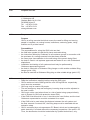
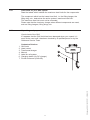
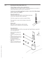
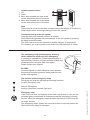
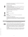
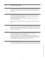
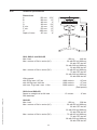
GB/US . . . . GH2 Ceiling Hoists
Vers. 2.01
1
GH2 Ceiling Hoists
Hoist numbers:
120001 - xxxx
1.00. . . . . . . . . Purpose and use. . . . . . . . . . . . . . . . . . . . . . . . . . . . . . . . . . . . . . . . . . . . . . 3
1.01 . . . . . . . . Manufacturer. . . . . . . . . . . . . . . . . . . . . . . . . . . . . . . . . . . . . . . . . . . . . . . . . . 3
1.02. . . . . . . . . Purpose and use. . . . . . . . . . . . . . . . . . . . . . . . . . . . . . . . . . . . . . . . . . . . . . . 3
1.03. . . . . . . . . Important – precautions. . . . . . . . . . . . . . . . . . . . . . . . . . . . . . . . . . . . . . . . . . 3
1.04. . . . . . . . . Load limits on your GH2 system. . . . . . . . . . . . . . . . . . . . . . . . . . . . . . . . . . . 4
1.05. . . . . . . . . Unpacking and preparation. . . . . . . . . . . . . . . . . . . . . . . . . . . . . . . . . . . . . . . 4
1.06. . . . . . . . . Mounting the lifting hanger before use . . . . . . . . . . . . . . . . . . . . . . . . . . . . . . 5
1.07. . . . . . . . . The lifting sling. . . . . . . . . . . . . . . . . . . . . . . . . . . . . . . . . . . . . . . . . . . . . . . . . 6
1.08. . . . . . . . . Before the hoist can be used. . . . . . . . . . . . . . . . . . . . . . . . . . . . . . . . . . . . . . 7
1.09. . . . . . . . . Power supply. . . . . . . . . . . . . . . . . . . . . . . . . . . . . . . . . . . . . . . . . . . . . . . . . . 7
1.10. . . . . . . . . The Swing-kit. . . . . . . . . . . . . . . . . . . . . . . . . . . . . . . . . . . . . . . . . . . . . . . . . . 8
1.11. . . . . . . . . GH2+2 ceiling hoist with built-in drive motor. . . . . . . . . . . . . . . . . . . . . . . . . . 9
1.12. . . . . . . . . GH2+2R ceiling hoist with built-in drive motor
. . . . . . . . . . . . . and infrared remote control . . . . . . . . . . . . . . . . . . . . . . . . . . . . . . . . . . . . . . . . . 9
2.00. . . . . . . . . Description of functions. . . . . . . . . . . . . . . . . . . . . . . . . . . . . . . . . . . . . . . 10
2.01. . . . . . . . . Pictograms. . . . . . . . . . . . . . . . . . . . . . . . . . . . . . . . . . . . . . . . . . . . . . . . . . . 10
2.02. . . . . . . . . Indicator lamps. . . . . . . . . . . . . . . . . . . . . . . . . . . . . . . . . . . . . . . . . . . . . . . . 11
2.03. . . . . . . . . Operation. . . . . . . . . . . . . . . . . . . . . . . . . . . . . . . . . . . . . . . . . . . . . . . . . . . . . 11
2.04. . . . . . . . . Safety functions. . . . . . . . . . . . . . . . . . . . . . . . . . . . . . . . . . . . . . . . . . . . . . . 12
2.05. . . . . . . . . Recharging. . . . . . . . . . . . . . . . . . . . . . . . . . . . . . . . . . . . . . . . . . . . . . . . . . . 13
2.06. . . . . . . . . Accessories. . . . . . . . . . . . . . . . . . . . . . . . . . . . . . . . . . . . . . . . . . . . . . . . . . 14
3.00. . . . . . . . . Transport . . . . . . . . . . . . . . . . . . . . . . . . . . . . . . . . . . . . . . . . . . . . . . . . . . . 15
5.00. . . . . . . . . Service and lifetime. . . . . . . . . . . . . . . . . . . . . . . . . . . . . . . . . . . . . . . . . . . 17
5.01. . . . . . . . . Lifetime . . . . . . . . . . . . . . . . . . . . . . . . . . . . . . . . . . . . . . . . . . . . . . . . . . . . . 17
5.02. . . . . . . . . Service inspection. . . . . . . . . . . . . . . . . . . . . . . . . . . . . . . . . . . . . . . . . . . . . 17
5.03. . . . . . . . . Troubleshooting. . . . . . . . . . . . . . . . . . . . . . . . . . . . . . . . . . . . . . . . . . . . . . . 18
6.00. . . . . . . . . Technical specifications. . . . . . . . . . . . . . . . . . . . . . . . . . . . . . . . . . . . . . . 19
7.00. . . . . . . . . EC declaration of conformity. . . . . . . . . . . . . . . . . . . . . . . . . . . . . . . . . . . 21
. . . . . . . . . . . . . USA and countries outside the EU . . . . . . . . . . . . . . . . . . . . . . . . . . . . . . 22
A.. . . . . . . . . . . Users guide. . . . . . . . . . . . . . . . . . . . . . . . . . . . . . . . . . . . . . . . . . . . . . . . . . 22
B. . . . . . . . . . . Warranty. . . . . . . . . . . . . . . . . . . . . . . . . . . . . . . . . . . . . . . . . . . . . . . . . . . . . 22
2
© Guldmann GB/US-1263/12/2011 • # 90069_2.01
4.00. . . . . . . . . Maintenance and storage. . . . . . . . . . . . . . . . . . . . . . . . . . . . . . . . . . . . . . 16
4.01. . . . . . . . . Cleaning. . . . . . . . . . . . . . . . . . . . . . . . . . . . . . . . . . . . . . . . . . . . . . . . . . . . . 16
4.02. . . . . . . . . Storage . . . . . . . . . . . . . . . . . . . . . . . . . . . . . . . . . . . . . . . . . . . . . . . . . . . . . 16
4.03. . . . . . . . . How to prevent and avoid corrosion . . . . . . . . . . . . . . . . . . . . . . . . . . . . . . . 16
4.04. . . . . . . . . Daily maintenance. . . . . . . . . . . . . . . . . . . . . . . . . . . . . . . . . . . . . . . . . . . . . 16
4.05. . . . . . . . . Disposal of GH2 incl. batteries . . . . . . . . . . . . . . . . . . . . . . . . . . . . . . . . . . . 16
1.00
Purpose and use
1.01 Manufacturer
V. Guldmann A/S
Graham Bells Vej 21-23A
DK 8200 Århus N
Tel. +45 8741 3100
Fax +45 8741 3131
www.guldmann.com
1.02
Purpose and use
Purpose
GH2 is a ceiling-mounted hoist that covers the need for lifting and moving
people in hospitals, at nursing homes, institutions, swimming pools, riding
schools and in private homes.
Preconditions
The preconditions for using the GH2 hoist are that:
• the staff who operate this aid facility have received training,
• the instruction offered by Guldmann to all customer groups in connection with
the purchase of a ceiling-mounted hoist has been received,
• the carer pays close attention to the well-being of the person being lifted,
• the hoist is used in rail systems approved and tested in acc. with Guldmann’s
stipulations,
• installation and testing of rail systems should only be performed by
Guldmann-approved engineers.
• the hoist is used with a Guldmann lifting hanger or with another suitable lifting
hanger (point 1.06),
• the hoist is used with a Guldmann lifting sling or other suitable slings (point 1.07).
© Guldmann GB/US-1263/12/2011 • # 90069_2.01
1.03
Important – precautions
• Read the instructions carefully before using the GH2 hoist.
• GH2’s maximum load of 200 kg/440 lbs. and 250 kg/550 lbs. respectively
must never be exceeded.
• GH2 may only be used to lift people.
• The red emergency stop and emergency lowering strap must be adjusted to
the user’s reach.
• GH2 must not be used where there is a risk of water being sprayed directly
onto it (Except for GH2 with protection class IP24).
• If the GH2 hoist fails while in use, it should not be used further, and the local
Guldmann representative must be contacted for a repair.
• If the GH2 hoist is used where the distance between the rail system and
the floor exceeds 3 metres/120”, the lifting strap must be extended with an
extension strap.
• GH2 is controlled by a microprocessor PC Board, which can be damaged by
static electricity if touched without the necessary precautions. See point 1.09.
Thus, the electronics should be looked after by quaified technicians, only.
3
1.04
Load limits on your GH2 system
Read the labels which indicate the maximum load limits for the components.
The component which has the lowest load limit, i.e. the lifting hanger, the
lifting sling, etc., determines the entire system’s maximum load limit.
This maximum load limit must not be exceeded.
Please note that the load may change when different components are used,
such as lifting hangers, lifting slings, etc.
Unpacking and preparation
Visual check of the GH2
If it appears that the GH2 hoist has been damaged when you unpack it, it
must not be used until it has been checked by a qualified person or by the
Guldmann Service Team.
Contents of the box
1. GH2 hoist
2. Hand control
3. Transformer/charger
4. Manual
5. Label for rail system
6. Charging station (for DC charger)
7. Friction enhancer (GH2+2R)
4
1
2
3
© Guldmann GB/US-1263/12/2011 • # 90069_2.01
1.05
1.06
Mounting the lifting hanger before use
Lifting hangers made by other manufacturers
Guldmann shall not be liable for faults or accidents that occur as a result of
using lifting hangers made by other manufacturers.
If you are in any doubt regarding the choice or use of the lifting hanger:
please contact your supplier.
Strap with snap hook
Use lifting hanger type 21X87 or the X lifting hanger type
21387 when using GH2 with a snap hook.
GH2 with a snap hook can also be used for Swing.
The snap hook is sewn onto the strap and cannot be
removed.
Please note
Bath chairs, bath stretchers, and horizontal
stretchers must be attached to the snap hook.
Strap attachment
Use lifting hanger type 21X70 or Horizontal Lifter Type BS when using GH2
with strap attachment.
•
•
•
•
•
Mount the lifting hanger as
illustrated.
Loosen the pointed screws
(2).
Release the axle journal (3).
Mount the lifting strap (1) on
the lifting hanger (4).
Introduce the axle journal
again (3).
Use a 1.5 mm Allen key to
tighten the pointed screws.
1
2
3
© Guldmann GB/US-1263/12/2011 • # 90069_2.01
4
5
The lifting sling
A lifting sling with four to six lifting straps designed
for mounting on hooks with a minimum diameter
of 8 mm/0.3” should be used when using a
Guldmann lifting hanger.
Slings made by other manufacturers
Guldmann shall not be liable for faults
or accidents that occur as a result of
using lifting slings made by other
manufacturers.
If you are in doubt regarding the
choice or use of the lifting sling:
please contact your supplier.
Guldmann shall not be liable for faults or accidents due to incorrect use of the
lifting sling, or for reasons of inadequate attention on the part of the carer or user.
Working with the GH2 hoist
It is only necessary to pay attention to the user’s functional level and the
carer’s technique, as the GH2 hoist makes no special requirements as
regards space or power consumption and runs easily in the rail system.
The user should only be lifted just clear of the underlying surface and
should be moved at this height.
Attaching the lifting sling
Attach the hooks that face the user to the uppermost set of straps (from the
back). Attach the lowermost set of straps (from the legs) to the hooks that
face away from the user.
Lifting to and from sitting position
When lifting a user from e.g. a wheelchair, move the GH2 towards the person
to be lifted.
The lifting hanger should be at the same height as the person’s chest and should
not be moved further in over the user than to approximately mid-thigh position.
Place the lifting hanger parallel to the user’s shoulders.
Place the lifting sling behind the user’s back between the back of the chair
and the user’s back.
The centre band of the lifting sling should follow the user’s spine. As for the
slings type Active the strap showing the size of the sling should be opposite
the spine. Lead the leg straps along the outer sides of the user’s shins and
beneath the thighs between the hollow of the knees and the hip joints. Cross
the leg straps over each other in front of the user.
All four lifting straps are now ready to be attached. The lifting sling can now
be mounted on the lifting hanger.
Lifting to and from lying position in bed
Bring the lifting hanger over the centre of the person to be lifted.
Place the lifting hanger parallel to the user’s shoulders.
Turn the user onto his or her side. The lifting high back sling should be placed
6
© Guldmann GB/US-1263/12/2011 • # 90069_2.01
1.07
so that its top is at the same height as the top of the user’s head. Now lay the
sling over the user so that the centre band follows the user’s spine. Turn the
user onto his or her back and pull out the remaining part of the lifting sling.
Place the leg straps beneath the user’s thighs and cross them over each
other. All four lifting straps are now ready to be attached and the lifting sling
can now be mounted on the lifting hanger. It is an advantage to elevate the
head of the bed so that the user is sitting up.
Only persons who have received competent instruction regarding the use of
lifting equipment and fitting of slings should start using the hoist.
1.08
Before the hoist can be used
Battery connection
Attach 4-pole plug in accordance with the enclosed
instructions. The measures regarding ESD-safety
are valid in this connection. See point 1.09.
Emergency stop device
The emergency stop device must be reset in order
to connect power to the product. To do this, push
the contact arm, to which the red emergency stop
band is fastened, towards the product until it clicks.
1.09
Power supply
GH2 is equipped with batteries that require regular recharging. The power
supply for charging and the battery charging point must be connected by a
qualified engineer or by the Guldmann Service Team.
The transformer/recharger supplied must always be used.
© Guldmann GB/US-1263/12/2011 • # 90069_2.01
AC power supply
When the power is supplied via the rails (Midi-rails), an AC transformer
Guldmann type DTS-2420, item No. 937000, must be used. For connection
please refer to the installation guide.
If AC power supply is used (MIDI rails), the hoist will after use be constantly
recharged throughout the length of the rail.
DC power supply
When the power is supplied via the charging station, a DC charger Mascot
type 2240, item No. 937030, must be used. For connection please refer to the
installation guide.
If DC power supply is used (MINI, MAXI and JUMBO rails), the hoist shall
after use be placed in the charging station for recharging. The charging
station is marked with - + on the rail.
Safety concerning static electricity (ESD)
Service technicians and installers must use an ESD-safety package
consisting of a mat, a ground wire, and a bracelet. The technician/installer
connects the mat to a grounding point, for instance a radiator or a water pipe.
He must then put on the bracelet and connect it to the mat. If the technician
7
is using a ladder, it is important that the mat is placed on the step on which
he is standing. If it is not possible to find a grounding point, the mat and the
bracelet must be used as a minimum.
Only then is it allowed to work with the PC Board or components where it is
possible to come into contact with the PC Board.
The Swing-kit
Note: If you wish to use the Swing-kit with the GH2 hoist, this must be
specified when ordering.
1. Bring the two hoists as close to each other as
possible.
The lifting hanger is attached to the hook on hoist B.
A
B
A
B
A
B
A
B
A
B
2. Pull out the free strap and hook from hoist A and
attach it to the eye.
3. Pull out the lifting strap on hoist B a little further and
retract the lifting strap on hoist A.
When the transfer swing has been completed there
is no longer any load on the lifting strap on hoist B.
4. Release the hook and strap from hoist B, which
now bears no load.
Return the lifting strap to hoist B until the hook is
needed again.
5. Return the lifting hanger on hoist A to working
height. The transfer through the door has now
been completed.
8
© Guldmann GB/US-1263/12/2011 • # 90069_2.01
1.10
1.11
GH2+2 ceiling hoist with built-in drive motor
GH2+2 ceiling hoist with a built-in drive motor operates fully automatically on
the rail system.
When using a GH2+2, please note that the motor uses approx. 1 second to
accelerate and stop the hoist, respectively. Thus, when stopping the unit from
max. speed, the motor must be cut off 10-15 cm before the desired position.
When the hand control is activated for a shorter period of time, it is possible
to position the hoist with a high level of accuracy.
GH2+2 must run on its own power and should not be pulled through the rail
system.
1.12
GH2+2R ceiling hoist with built-in drive motor and infrared remote control
GH2+2R has a built-in drive motor and IR receiver which is controlled by the
IR sender.
With this sender, it is possible to control all the functions of the hoist.
Furthermore, the IR sender can be used to control e.g. switch tracks,
combi-locks and turntables mounted with IR receivers.
The cable-mounted hand control must remain fitted to the hoist. This will
ensure that the hoist can always be operated if the IR sender is mislaid
or if its batteries run dry.
In certain cases, an unladen hoist with a drive motor can, due to its low
unloaded weight, have difficulty in driving through, for example, switch
tracks, if the switch is not open in the direction in which the hoist is passing.
To provide extra security for unassisted users that the hoist runs smoothly
through the track system, it is possible to mount a friction enhancer in
connection with the hoist’s drive wheels. Friction enhancers cannot be
used in connection with a drive-through charging station.
Friction enhancers are mounted as follows:
1. Move the hoist to the end of the rail, making sure that the drive wheels are
free of the rail.
© Guldmann GB/US-1263/12/2011 • # 90069_2.01
2. The friction enhancer is placed over the wheels as shown. The long pins on
the friction enhancer must point in the direction of the nearest end of the hoist.
3. Run the hoist into the rail again. Check
that the friction enhancer is functioning by
holding onto the hoist with the drive motor
in operation. The hoist must pull strongly
in both drive directions.
9
2.00
Description of functions
The information panel on the GH2 hoist as seen from the floor.
Pictograms
Charging Emergency
Emergency
indicator
lowering
stop
Example of a serial number label
– see variants of GH2 ceiling hoists under point 6.00
Direction of
travel for GH2+2
with drive motor
No. 120001-1001-2005
max 200 kg/440 lbs
24V AC/DC. FUSE 15AF. 240VA. ED15% IP20
V. Guldmann A/S, Graham Bells Vej 21-23A
DK-8200 Århus N, Tel. +45 8741 3100, www.guldmann.com
No. 120001-1001-2005
max 250 kg /550 lbs
24V AC/DC. FUSE 5AF. 75 VA. ED15% IP20
V. Guldmann A/S, Graham Bells Vej 21-23A
DK-8200 Århus N, Tel. +45 8741 3100, www.guldmann.com
10
© Guldmann GB/US-1263/12/2011 • # 90069_2.01
2.01
CE-marking
Type B in accordance with EN 60601-1
Read instructions before use
Permissible operation time, for instance operation 3 min. and pause 20 min.
Please don’t throw away with household rubbish, but recycle the product
2.02
Indicator lamps
The colours and functions are as described below:
2.03
Green
On
Blinking
Off
The hoist is active.
The hoist batteries need recharging.
The hoist is switched off.
Yellow
On
Charging indicator indicates that connection is established
between the hoist and the recharger/transformer.
Operation
Hand control
Pressing a button on the hand control automatically switches on the GH2 hoist.
The GH2 will automatically switch off after approximately ten minutes when
not in use.
© Guldmann GB/US-1263/12/2011 • # 90069_2.01
1. Lift
2. Lower
1
1
2
1.
2.
3.
4.
4
Lift
3
2
Lower
Move hoist towards the open arrow on the information panel of the hoist
Move hoist towards the closed arrow on the information panel of the hoist
11
Infrared remote control
1. Lift
2. Lower
3. Move hoist towards the open arrow
on the information panel of the hoist
4. Move hoist towards the closed arrow
on the information panel of the hoist
1
2
3
4
Note
There must be a load on the strap corresponding to the weight of Guldmann’s
lifting hanger before the lifting/lowering function will operate.
Transport/running in the rail system
Push the GH2 hoist manually into the rail system.
GH2+2/GH2+2R operates fully automatically on the rail system by pressing
the hand control/IR sender.
The GH2 hoist must not be exposed to sudden changes in temperature.
For instance, you must not take a cold hoist into a hot bathroom or similar.
Safety functions
The emergency stop and emergency lowering
device should be used only in an emergency
If, contrary to expectations, it becomes necessary to
use the safety functions, the fault must be located and
remedied before using the GH2 hoist again.
Please contact your supplier.
Re: EMC
If electromagnetic or other influences occur between
this product and other products, these products must
not be used together.
The function of the emergency strap
Pulling the red strap will activate the following functions:
• 1st pull: Emergency stop
• 2nd pull: Emergency
lowering (requires a constant, light pull).
Emergency stop
If the GH2 hoist does not respond to the hand control when in use, pull the
red strap lightly to deactivate all functions except the emergency lowering
function. When the emergency stop has been activated, the GH2 hoist will
no longer function.
The emergency stop’s contact arm must be pushed in manually before the
GH2 hoist will be ready for use again.
12
© Guldmann GB/US-1263/12/2011 • # 90069_2.01
2.04
After deactivation of the emergency stop, activate the hand control twice.
• the first time to reset the PC Board
• the second time to switch on the hoist
Emergency lowering
If the GH2 hoist breaks down, the electric emergency lowering device can
be used to lower the user safely.
The emergency lowering device is operated by a constant pull on the red
strap which is also used to activate the emergency stop.
If the red strap is not pulled constantly, the emergency stop will be active
rather than the emergency lowering device, and it will not be possible to
operate the GH2 hoist before the unit is reset.
Explanation to labels:
Type B
In accordance with EN 60601-1.
Warning
Before use, cleaning and service read the user manual/technical
documentation.
Description of strap safety device
Overloading the hoist, pulling the strap crookedly, or if the strap is twisted, the
strap safety device will be activated, and the GH2 hoist will be deactivated.
If the yellow mark on the strap is visible, it is not allowed to lift with maximum
load.
© Guldmann GB/US-1263/12/2011 • # 90069_2.01
2.05
Recharging
When the GH2 hoist is not in use it should be parked in the recharging unit.
This will maintain the batteries and ensure them a long lifetime.
When GH2 is being recharged, the yellow charging indicator on GH2’s information face is illuminated. The indicator light flashes while the batteries are
being recharged. The light indicates that the GH2 hoist and the transformer/
charger are correctly connected. The green circle of lamps on the bottom of
the hoist will blink if the batteries are running low – the GH2 hoist will then
be able to lift only a certain number of times, and the batteries must be
recharged.
To recharge the batteries, place the GH2 hoist in the charging unit marked
with the battery symbol on the rail. The batteries in a GH2 hoist installed in
a MIDI rail will be constantly recharged throughout the length of the rail.
13
Accessories
Guldmann – ABC lifting sling and lifting hanger
Order a special brochure from your distributor, the manufacturer or
www.guldmann.com.
Extension strap
The extension strap must be used wherever the distance between the lower
edge of the rail and the floor exceeds 3 metres/120”. For example, if the
distance between the rail and the floor is 3.5 metres/140”, you should order
a 500 mm/20” extension strap.
Switch track, manual and electric
Switch tracks are used for changing direction
in a rail system. Manual switch tracks are
activated by pulling on a cord attached
to the switch tracks. This changes the
direction of travel, and GH2 then runs
in the direction indicated by the cord.
Electric switch tracks are activated
by pressing the attached hand control.
Safety
This product is mechanically protected against derailment and jamming.
Turntable
The turntable is used in track systems
where the hoist needs to run in several
directions.
The turntable must not be used with the
GH2 HD hoist.
The GH2 motor is powered into the
center of the turntable. By pressing the
switch, the turntable rotates 90°. Press
again, and the turntable returns to the first
position.
Safety
This product is mechanically protected against derailment and jamming.
14
© Guldmann GB/US-1263/12/2011 • # 90069_2.01
2.06
Combi-lock, manual and electric
The Combi-lock is used when a singletrack rail system is to be linked up to
a room-covering rail system, or when
two room-covering rail systems need
linking.
The Combi-lock ensures that the two
systems are locked together in situations such as transfer from a singletrack rail system in a bedroom to a
room-covering system in a bathroom.
The Combi-lock is available as an
electric or a manual model. It is
activated by either pressing the
switch or pulling on the cord.
Safety
This product is mechanically protected against derailment and jamming.
Infrared remote control
Switch tracks, turntable and combi-locks can be supplied with receivers for
IR remote control.
Batteries
Battery Guldmann type FG20401, item No. 933015
Charger
Charger Mascot type 2240, item No. 937030
Transformer
Transformer Guldmann type DTS-2420, item No. 937000
3.00
Transport
Guldmann recommends that the GH2 hoist is always transported and stored
in the original packaging.
© Guldmann GB/US-1263/12/2011 • # 90069_2.01
Explanation of symbols on the GH2 packaging:
-10
14
40°C
104°F
30
70%
700
1060hPa
GH2 should be stored at temperatures between -10 and +40°C /14 and 104°F.
GH2 should be stored at an air humidity between 30 and 70%.
GH2 should be stored at an air pressure between 700 and 1060hPA.
15
4.00
Maintenance and storage
4.01
Cleaning
Clean the GH2 hoist with a damp cloth and standard household detergent.
Never clean GH2 with strong acid, base or alcohol. Never clean GH2 in an
autoclave.
4.02
Storage
The GH2 hoist should be stored in a dry room with a maximum humidity
of 70%. The hoist should be stored with the emergency stop activated to
prevent consumption of battery power.
For long-term storage, remove the 4-pole plug with white, black, red and
yellow connection leads.
4.03
How to prevent and avoid corrosion
If the GH2 hoist is mainly used in corrosive surroundings, such as swimming
pools, it must be ordered with a special corrosion-preventive surface treatment.
Do not expose GH2 to sudden cold/heat, as an example do not move a cold
GH2 into a hot bathroom.
4.04
Daily maintenance
Check the lifting sling for wear and damage before using the hoist.
Never use a damaged or defective lifting sling.
Never use the GH2 hoist if the lifting strap is damaged or defective.
Contact your supplier to order a new lifting sling or lifting strap replacement.
The lifting strap may be replaced only by the Guldmann Service Team or by
a qualified fitter in accordance with Guldmann’s instructions.
4.05
Disposal of GH2 incl. batteries
Local and national regulations for environmentally responsible recycling must
be observed. Batteries should always be taken to approved recycling points.
16
© Guldmann GB/US-1263/12/2011 • # 90069_2.01
The measures regarding ESD-safety are valid in this connection. See point
1.09.
5.00
Service and lifetime
5.01
Lifetime
GH2 has an expected lifetime of 15 years, provided that the service
inspections mentioned under point 5.02 are observed.
Replacing components
Batteries, printed circuit boards and lifting straps may be replaced only by a
qualified fitter or by the Guldmann Service Team.
5.02
Service inspection
According to the international standard EN/ISO 10535 “Hoist for the transfer
of disabled persons - Requirements and test methods” a safety inspection of
the hoist must be performed at least one a year.
The GH2 must be inspected by a qualified fitter or by the Guldmann Service
Team.
The service inspection includes a written report specifying what has been
inspected and replaced.
Worn or defective components must be replaced by new components from
Guldmann.
Spare parts drawings and documentation can be ordered from the manufacturer or the distributor.
1. Visual inspection of the hoist
• Check for wear, irregularities or other types of damage to the hoist
2. Testing the hoist as though in normal use
• Check all functions of the product with and without load as described in
section 2.
• Check that the emergency stop functions
• Check that the emergency lowering device functions
• Check that the green indicator lamp lights up when the hoist is activated
• Check that the yellow charging indicator lights up when the batteries are
recharging
© Guldmann GB/US-1263/12/2011 • # 90069_2.01
3. Remove cover/screen
4.
•
•
•
•
•
•
Checking the electrical state of the hoist
Check batteries for:
• Input voltage
• Output voltage
Check electrical functions and signals
Check the wiring circuit for faults or defects
Check the cable lead-ins
Check the power supply, plugs, etc.
Check the electrical safety of the product according to IEC 60601-1/1988
17
5.
•
•
•
•
•
•
Checking the mechanical state of the hoist
Clean the hoist to remove dirt and other impurities
Inspect and evaluate vital components
Replace defective and worn components
Check and tighten all moving parts
Lubricate the hoist
Where applicable, treat the surface with silicone oil
6. Replace cover/screen
7. Go through the checkpoints under item 2 again to make sure that .
everything functions
8. Have new problems arisen or been found under item 7?
• If new problems have arisen, return to item 3
• If there are no new problems, the inspection is completed
9. When a service inspection including service work or exchange of .
components has taken place, the final check must comprise a weight
test with the product’s nominal load.
Troubleshooting
Does the GH2 hoist fail to respond when buttons on the hand control
are pressed?
• Check that the emergency stop has not been activated
• Check that power is supplied to the hoist
• Contact the Guldmann Service Team
The hand control may be defective
Does the green lamp on the hoist blink when the batteries are .
recharging?
• Check that the yellow charging indicator lights up when the hoist is put in the
recharging position
• Check that the power supply is switched on
• Contact the local Guldmann representative or the Guldmann Service Team
18
© Guldmann GB/US-1263/12/2011 • # 90069_2.01
5.03
6.00
Technical specifications
Dimensions
A
B
C
D
E, min.
F, min.
G
Depth of Hoist
595
300
148
160
82
370
1850
197
mm 23¾”
mm
12”
mm
6”
mm 6½”
mm 2½”
mm
15”
mm
73”
mm
8”
GH2, GH2+2 and GH2+2R
Max. load . . . . . . . . . . . . . . . . . . . . . . . . . . . . . . . . . . . . 200 kg . . . . . 440 lbs.
Max. number of lifts in series (AC) . . . . . . . . . . . . . . . 92 with 85 kg/1000 mm
92 with 187 lbs./40”
36 with 200 kg/1000 mm
36 with 440 lbs./40”
Max. number of lifts in series (DC) . . . . . . . . . . . . . . . 72 with 85 kg/1000 mm
72 with 187 lbs./40”
32 with 200 kg/1000 mm
32 with 440 lbs./40”
Lifting speed:
with 85 kg load / 187 lbs. . . . . . . . . . . . . . . . . . . 1680 mm/min . . . . . . 66”/min
with 200 kg load / 440 lbs. . . . . . . . . . . . . . . . . . 1200 mm/min . . . . . . 47”/min
with max. 5 kg load / max. 11 lbs. . . . . . . . . . . . 3300 mm/min . . . . . 130”/min
(Dual-speed)
© Guldmann GB/US-1263/12/2011 • # 90069_2.01
GH2+2 and GH2+2R
Speed on straight rail at full load . . . . . . . . . . . . . . . 15 cm/sec. . . . . . . 6”/sec.
Soft start/stop
GH2 HD
Max. load . . . . . . . . . . . . . . . . . . . . . . . . . . . . . . . . . . . . 250 kg . . . . . 550 lbs.
Max. number of lifts in series (AC) . . . . . . . . . . . . . . . 92 with 85 kg/1000 mm
92 with 187 lbs./40”
32 with 250 kg/1000 mm
32 with 550 lbs./40”
Max. number of lifts in series (DC) . . . . . . . . . . . . . . . 72 with 85 kg/1000 mm
72 with 187 lbs./40”
28 with 250 kg/1000 mm
28 with 550 lbs./40”
19
Lifting speed:
with 85 kg load / 187 lbs. . . . . . . . . . . . . . . . . . . 1680 mm/min . . . . . . 66”/min
with 250 kg load / 550 lbs. . . . . . . . . . . . . . . . . . 1020 mm/min . . . . . . 40”/min
with max. 5 kg load / max. 11 lbs. . . . . . . . . . . . 3300 mm/min . . . . . 130”/min
(Dual-speed)
GH2, GH2+2, GH2+2R and GH2 HD
Weight:
GH2 & GH2 HD excl. lifting hanger . . . . . . . . . . . . . . . . 8,7 kg . . . . . . 18 lbs.
GH2+2 & GH2+2R excl. lifting hanger . . . . . . . . . . . . . 9,0 kg . . . . . . 20 lbs.
Lifting hanger . . . . . . . . . . . . . . . . . . . . . . . . . . . . . . min. 2,0 kg . . . . . . 4.4 lbs.
Sound level acc. to DS/ISO 3746:
Lifting motor. . . . . . . . . . . . . . . . . . . . . . . . . . . . . . . . . . . . . . . . . . . . . 52 dB(A)
Drive motor . . . . . . . . . . . . . . . . . . . . . . . . . . . . . . . . . . . . . . . . . . . . . 52 dB(A)
Protection class:
Hoist and hand control. . . . . . . . . . . . . . . . . . . . . . . . . . . . . . . . . . . IP20 / IP 24
Microswitches in hand control. . . . . . . . . . . . . . . . . . . . . . . . . . . . . . . . . . . IP67
Safety Measures
Safety cut off for strap . . . . . . . . . . . . . . . . . . . . Approx. 45º, driving direction
Approx. 10º, transverse direction
Battery protection
at too low voltage . . . . . . . . . . . . . . . . . . . . . . . . . . Switches off when voltage
goes below 17 volt
Periodic load, lifting motor
(operation/pause). . . . . . . . . . . . . . . . . . . . . . . . . . 15/85, dynamic supervision
Periodic load, drive motor
(operation/pause) . . . . . . . . . . . . . . . . . . . . . . . . . 20/80, dynamic supervision
20
© Guldmann GB/US-1263/12/2011 • # 90069_2.01
Electrical specifications
Power supply. . . . . . . . . . . . . . . . . . . . . . . . . . . . . . . . . . . . . . . . . . . . . 25V AC
Power supply. . . . . . . . . . . . . . . . . . . . . . . . . . . . . . . . . . . . . . . . . . . . . 24V DC
Output transformer. . . . . . . . . . . . . . . . . . . . . . . . . . . . . . . . . . . . . . . . . . . 40VA
Outpout recharger. . . . . . . . . . . . . . . . . . . . . . . . . . . . . . . . . . . . . . . . . . . 32VA
Supply voltage transformer or recharger . . . . . . . . . . . . . . . . . . . . . 100 - 240V
Current consumption, GH2 . . . . . . . . . . . . . . . . . . . . . . . . . . 8.5A at max. load
Current consumption, GH2+2 drive motor . . . . . . . . . . . . . . 2.5A at max. load
Max. power consumption GH2 . . . . . . . . . . . . . . . . . . . . . . . . . . . . . . . . 240VA
Charging time . . . . . . . . . . . . . . . . . . . . . . . . . . . . . . . . . . . . . . . . max. 8 hours
Lead batteries, sealed and maintenance-free . . . . . . . . . . . . . . . . . . . 2 x 12V
Rechargeable batteries . . . . . . . . . . . . . . . . . . . . . . . . . . . . . order no. 933015
7.00
EC declaration of conformity
EC-DECLARATION OF CONFORMITY
Manufacturer
V. Guldmann A/S
Graham Bells Vej 21-23A
DK-8200 Aarhus N
EAN country code: 57
EAN distribution No.: 07287
Phone +45 8741 3151
Fax
+45 8741 3131
Representative
Company
Address
Country
Phone
Hereby declare that
Product
GH2, GH2+2, GH2+2R & GH2 HD
incl. lifting hanger, suspension and charging system
Type No.
XXXXXX-YYYY-ZZZZ x)
x)
XXXXXX: Reference No. of the product, YYYY: Serial No. of the product in the production year,
ZZZZ: Production year
was manufactured in conformity with the provisions in:
Hoists for the transfer of disabled persons
- requirements and test methods
• EN 60601-1:1990 Medical electrical equipment + A1: 1993
Part 1-1: General requirements for safety
+ A2: 1995
+ A12: 1993
• EN 60601-1-2:
Medical electrical equipment Part 1: General requirements for safety 2: Collateral standard: Electromagnetic compatibility
© Guldmann GB/US-1263/12/2011 • # 90069_2.01
• EN 10535:
according to the Council Directive 93/42/EEC of 14 June 1993
Skejby 01.09.03
Place and day of issue
Product responsible
Technical Manager
21
USA and countries outside the EU
A.
Users guide
Before using the product, read the entire operation manual
including warranty.
B. WARRANTY
Guldmann warrants its equipment is free from material defects under normal
use, and will perform substantially in accordance with the specifications set
forth in documentation provided with the equipment.
This express warranty shall be in effect for one year from the date of original
purchase and installation (the “Warranty Period”). If a valid claim is made
during the Warranty Period for malfunction or equipment defect, Guldmann
will repair or replace the equipment at no additional cost to you. Guldmann
retains sole discretion as to whether the equipment will be repaired or replaced.
This warranty shall be null and void if the equipment is operated and maintained in any manner inconsistent with its intended use or the instructions
provided with the product. Further, in order for the warranty to remain in effect
for the full Warranty Period, all service to the equipment must be provided
by a Guldmann designated technician. Any parts or components repaired or
replaced by a Guldmann designated technician will be guaranteed for the
remainder of the Warranty Period.
The warranty set forth is in lieu of all other express and implied warranties,
whether oral, written or implied, and the remedies set forth above are your
sole and exclusive remedies. Only an authorized officer of Guldmann may
make modifications to this warranty, or additional warranties binding on Guldmann. Accordingly, additional statements such as advertising or presentations, whether oral or written, do not constitute warranties by Guldmann.
Service or Repair
Contact Guldmann Repair for an authorization to return any defective item
during the Warranty Period. You will be provided with a return authorization
number and address for returning the item for warranty service or replacement. Do not return items to Guldmann under warranty without receiving a
Return Authorization Number.
22
© Guldmann GB/US-1263/12/2011 • # 90069_2.01
The warranty does not cover any part of the equipment which has been subject to damage or abuse by the user or others. The warranty does not cover
any part of the equipment which has been altered or changed in any way by
the user or others. Guldmann does not warrant that the lifting device functions
will meet your requirements, be uninterrupted or error free.
© Guldmann GB/US-1263/12/2011 • # 90069_2.01
If mailing the item, pack it carefully in a sturdy carton to prevent damage.
Include your Return Authorization Number, a brief description of the problem
and your return address and phone number. Guldmann does not assume the
risk of loss or damage while in transit, so it is recommended you insure the
package.
23
© Guldmann GB/US-1263/12/2011 • # 90069_2.01
V. Guldmann A/S
Corporate Office:
Graham Bells Vej 21-23A
DK-8200 Århus N
Tlf.
+45 8741 3100
Fax
+45 8741 3131
[email protected]
www.guldmann.dk
Guldmann Inc.
14401 McCormick Drive,
Unit A
Tampa, FL 33626
Tel.
800 664 8834
Tel.
813 880 0619
Fax
813 880 9558
[email protected]
www.guldmann.net