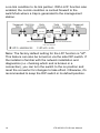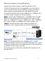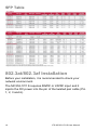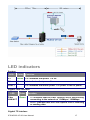
1
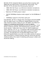
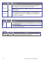
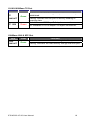
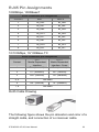
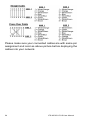
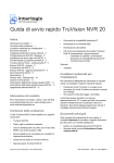
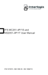
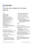
IFS MC352-1P/1S User Manual
P/N 1072579 • REV R00.03 • ISS 10SEP12
Copyright
Trademarks and
patents
Manufacturer
Version
Certification
FCC compliance
ACMA
compliance
European Union
directives
© 2012 UTC Fire & Security Company. All rights
reserved.
Interlogix, IFS MC352-1P/1S, the IFS Brand and
logo are trademarks of UTC Fire & Security.
Other trade names used in this document may be
trademarks or registered trademarks of the
manufacturers or vendors of the respective
products.
UTC Fire & Security Americas Corporation, Inc.
2955 Red Hill Avenue, Costa Mesa, CA
92626-5923, USA
This document applies to IFS MC352-1P/1S
version 1.0.
N4131
Class A: This equipment has been tested and
found to comply with the limits for a Class A digital
device, pursuant to part 15 of the FCC Rules.
These limits are designed to provide reasonable
protection against harmful interference when the
equipment is operated in a commercial
environment. This equipment generates, uses,
and can radiate radio frequency energy and, if not
installed and used in accordance with the
instruction manual, may cause harmful
interference to radio communications. Operation
of this equipment in a residential area is likely to
cause harmful interference in which case the user
will be required to correct the interference at his
own expense.
Notice! This is a Class A product. In a domestic
environment this product may cause radio
interference in which case the user may be
required to take adequate measures.
2004/108/EC (EMC directive): Hereby, UTC Fire
& Security declares that this device is in
compliance with the essential requirements and
other relevant provisions of Directive 2004/108/EC
2002/96/EC (WEEE directive): Products marked
with this symbol cannot be disposed of as
unsorted municipal waste in the European Union.
For proper recycling, return this product to your
local supplier upon the purchase of equivalent
new equipment, or dispose of it at designated
collection points. For more information see:
www.recyclethis.info.
Contact
information
Customer support
www.utcfireandsecurity.com or
www.interlogix.com
www.interlogix.com/customer-support
Contents
Overview 1
Package Contents 1
Product Description 2
Hardware Overview 4
Front Panel 5
Top Panel 6
Wiring the Power Inputs 6
Wiring the Fault Alarm Contact 7
Mounting Installation 8
Link Fault Pass through (LFP) 12
Link Loss Carry Forward (LLCF) 12
Link Loss Return (LLR) 13
Stand-alone Installation 15
802.3at/802.3af Installation 16
LED indicators 17
Cable Connection 20
Specifications 21
RJ45 Pin Assignments 23
Contacting Technical Support 25
IFS MC352-1P/1S User Manual
i
Overview
The MC352-1P/1S Industrial 802.3at High Power over Ethernet
Gigabit Media converter fully complies with IEEE 802.3
10Base-T, IEEE 802.3u, 100Base-TX, IEEE 802.3ab
1000Base-T and IEEE 802.3z 1000Base-SX / LX standards.
The Gigabit media conversion is quick and easy by simple
plug and play installation. The MC352-1P/1S series Industrial
802.3at High Power over Ethernet Gigabit Media converter
also supports flow control and back pressure in half-duplex
operation to eliminate packet loss.
Package Contents
Check the contents of your package for the following parts:
•
MC352-1P/1S x1
•
User’s Manual x1
•
DIN Rail Kit x 1
•
Wall Mount Kit x 1
If any of these items are missing or damaged, please contact
your distributor or IFS sales rep immediately. If possible, retain
the original carton and packaging material in case you need to
return the product for repair/replacement.
IFS MC352-1P/1S User Manual
1
Product Description
The MC352-1P/1S extends communication distance with high
Gigabit performance via fiber optical wire, in which the
extension distance can be up to 70km. The MC352-1P/1S is
specifically designed with durable components and an IP-30
rated enclosure to operate reliably in electrically and
demanding environments. The industrial Gigabit media
converter provides a high level of immunity to electromagnetic
interference and heavy electrical surges which are usually
found on plant floors or traffic control cabinets along highways.
Being able to operate under the temperature range from -40 to
75 Degree C allows the MC352-1P/1S to be used in almost
any demanding environment.
The maximum distance between the PoE PSE to PD is 100
meters. To extend the network device deployment range, the
MC352-1P/1S is designed with a fiber interface. The MC3521P/1S is used to convert an optical Ethernet signal to an
electrical Ethernet signal that allows two type segments to
connect easily, efficiently and inexpensively. It can convert
10/100/1000Base-T signal to 1000Base-SX / LX and provides
the diverse options of fiber connecting types to meet different
network applications.
With the long Fiber distance support, it still sustains the
transmission performance as high as 1000Mbps. It works in a
high performance Store and Forward mechanism, and also
can prevent packet loss with IEEE 802.3x Flow Control (FullDuplex) and the LFP (Link Fault Pass Through function)
(LLCF/LLR) with a DIP Switch setting. Furthermore, it can
immediately notify the network administrator the issue with an
alarm from the link media which provides an efficient solution
to monitor the network power usage.
To fill the growing demand of Industrial PoE PD devices that
need higher Power Input and long distance transmission, the
2
IFS MC352-1P/1S User Manual
MC352-1P/1S Industrial Media converter that complies with
IEEE 802.3at High Power over Ethernet technology. The
MC352-1P/1S provides the following key features:
•
IEEE 802.3at Power over Ethernet standard compliance
•
IEEE 802.3af Power over Ethernet standard compliance
•
Maximum 30 Watts power output
•
10/100/1000Mbps duplex mode support on the1000Base-T
port
•
1000Mbps support on the fiber optic port
The MC352-1P/1S is a Single-Port, End-Span Industrial IEEE
802.3at High Power over Ethernet Gigabit Media converter
with maximum power output of up to 30 Watts over Ethernet
cables. It is designed specifically to meet the power
requirements of network equipment such as PTZ (Pan, Tilt &
Zoom) network cameras, PTZ Speed Dome cameras, color
touch-screen / Video and Voice over IP (VoIP) telephones,
multi- channel (11a / b / g / n) wireless LAN access points and
other Network devices that need higher power to function
normally. The MC352-1P/1S Industrial High Power over
Ethernet Gigabit Media converter is an ideal solution to deliver
data and power to network devices directly via the RJ-45 Port
interface without the need of installing extra power outlets and
electrical cabling.
IFS MC352-1P/1S User Manual
3
Hardware Overview
Figure 1: All Panel Views
4
IFS MC352-1P/1S User Manual
Front Panel
The Front Panel of the Industrial 802.3at PoE Media Converter
consists of one 1000Base-SX / 1000Base-LX / mini-GBIC SFP
port and one Auto-Sensing 10/100/1000Mbps Ethernet RJ-45
Port.
IFS MC352-1P/1S User Manual
5
Top Panel
The top panel of the MC352-1P/1S Media Converter consists of
one terminal block connector within two DC power inputs.
Wiring the Power Inputs
The 6-contact terminal block connector on the top panel of the
MC352-1P/1S is used for two DC redundant power inputs.
Please follow the steps below to insert the power wires.
1. Insert positive / negative DC power wires into the contacts
1 and 2 for POWER 1, or 5 and 6 for POWER 2.
V1- V1+
V2- V2+
2. Tighten the wire-clamp screws to prevent the wires from
disconnecting.
6
IFS MC352-1P/1S User Manual
1
-
2
Power 1
3
4
5
Fault
6
Power 2
+
-
+
Wiring the Fault Alarm Contact
The fault alarm contacts are in the middle of the terminal block
connector as the picture shows below. Inserting the wires, the
MC352-1P/1S will detect the fault status of the power failure
and then forms an open circuit. The following illustration shows
an application example for wiring the fault alarm contacts.
1
2
3
4
5
6
Insert the wires into the fault alarm contacts
IFS MC352-1P/1S User Manual
7
Note: The wire gauge for the terminal block should be in the
range between 12 ~ 24 AWG.
The alarm relay circuit accepts up to 30V, max. 3A currents.
Mounting Installation
This section describes how to mount the MC352-1P/1S and
make connections to it. Please read the following sections and
perform the procedures in the order presented.
Note: In the installation steps below, this Manual uses the IFS
GE-DSGH-8 as an example. However, the steps for any IFS
Industrial Switch & Industrial Media Converter are similar.
Mounting to a DIN-Rail
The DIN-Rail kit comes assembled on the MC352-1P/1S out of
the box. Please refer to following figures to mount the MC3521P/1S on a DIN-Rail.
8
IFS MC352-1P/1S User Manual
1. Lightly press down and push the bottom of the DIN-Rail
connector mount into the track.
2. Check that the DIN-Rail connector mount is tightly mounted
on the track.
3. Please refer to following procedures to remove the MC3521P/1S from the track.
IFS MC352-1P/1S User Manual
9
4. Lightly press down and pull the bottom of the DIN-Rail
connector mount to remove it from the track.
Mounting to a Wall
To install the MC352-1P/1S on the wall, please follow the
instructions described below.
1. Loosen the screws to remove the DIN Rail from the Media
Converter.
10
IFS MC352-1P/1S User Manual
2. Place the wall mount plate on the rear panel of the MC3521P/1S.
3. Assemble the wall mount plate on the MC352-1P/1S.
4. Use the hook holes at the corners of the wall mount plate
to mount the MC352-1P/1S on the wall.
IFS MC352-1P/1S User Manual
11
Link Fault Pass through (LFP)
The LFP refers to the Link Fault Pass Through function
(LLCF/LLR) and the DIP Switch settings. LLCF/LLR can
immediately notify administrators about a problem with the link
media. The DIP Switch enables or disables the LFP function.
LLCF (Link Loss Carry Forward) detects the connection loss
on the TP line, and LLR (Link Loss Return) detects the
connection loss on the fiber line.
Link Loss Carry Forward (LLCF)
MC352-1P/1S incorporates an LLCF function for
troubleshooting a remote connection. When the LFP function
is enabled, the FL/TP ports do not transmit a link signal until
they receive a link signal from the opposite port.
The diagram below shows a typical network configuration with
a good link status using MC352-1P/1S for remote connectivity.
In case of a connectivity issue, the MC352-1P/1S media
converter LLCF sends the notification to the switch/hub that
generates a trap to the management station.
12
IFS MC352-1P/1S User Manual
* The factory default setting for the LFP function is "off".
Link Loss Return (LLR)
The fiber ports of the MC352-1P/1S have been designed with
an LLR function for troubleshooting a remote connection. LLR
works in conjunction with LLCF.
When the LFP function is enabled, the port’s transmitter shuts
down when its receiver fails to detect a valid connection. LLR
should only be enabled on one end of the link and is typically
enabled on either the unmanaged or remote device.
The diagram below shows a typical network configuration with
a good link status using MC352-1P/1S for remote connectivity.
Note that LLR and LLCF are enabled as indicated in the
diagram.
If one of the optical conductors is bad (as shown in the
diagram box below), the converter with LLR function will return
IFS MC352-1P/1S User Manual
13
a no-link condition to its link partner. With LLCF function also
enabled, the no-link condition is carried forward to the
switch/hub where a trap is generated to the management
station.
Note: The factory default setting for the LFP function is "off".
This feature can also be turned on via the side DIP-switch. If
the installer is familiar with the network installation and
diagnostics (i.e. checking which end is broken in a
connection), you can turn the switch to the on position and
reset the converter for changes to take effect. Otherwise, it's
recommended to keep the DIP switch in its default position.
14
IFS MC352-1P/1S User Manual
Stand-alone Installation
Please follow these steps to install the MC352-1P/1S:
The SFP transceivers are hot-swappable, you can insert or
remove the transceiver from an SFP port without having to
power down the Industrial 802.3at PoE Media Converter.
To install the MC352-1P/1S with 100Base-FX, 1000Base-SX /
LX SFP, simply complete the following steps:
Step 1: Insert in the 100Base-FX, or 1000Base-SX / LX SFP.
Make sure the same type of SFP modules are used on both
side, i.e. 100Base-FX / 2km to 100Base-FX / 2km, 1000BaseSX / 220m & 550m to 1000Base-SX / 220m & 550m, etc.
Step 2: Connect the fiber cable. Attach the duplex LC
connector on the network cable into the SFP transceiver.
Note: It is recommended to use 1000Base-SX / LX SFP
modules available in the IFS Transmission product line. A SFP
transceiver module that is not supported will not be recognized
by MC352-1P/1S media converter.
The following list provides the available SFP modules for the
MC352-1P/1S.
IFS MC352-1P/1S User Manual
15
SFP Table
802.3at/802.3af Installation
Before your installation, it is recommended to check your
network environment.
The MC352-1P/1S requires 48VDC or 24VDC input and it
injects the DC power into the pin of the twisted pair cable (Pin
1, 2, 3 and 6).
16
IFS MC352-1P/1S User Manual
LED indicators
System:
LED
Color
Function
P1
Green
Lit: indicates that power 1 is on.
P2
Green
Lit: indicates that power 2 is on.
FAULT
Green
Lit: indicates that either power 1 or power 2 has no power.
Gigabit Fiber Interface
LED
Color
Fiber
LNK/ACT
Green
Function
Lit: indicates that the Fiber Optical Port is successfully
connecting to the network at 100Mbps / 1000Mbps.
Blinks: indicates that the Fiber Optical Port is receiving
or sending data.
Gigabit TP Interface
IFS MC352-1P/1S User Manual
17
LED
Color
Function
Lit: indicates that the Gigabit Ethernet Port is successfully
connecting to the network at 10/100/1000Mbps.
TP
LNK/ACT
Blinks: indicates that the Gigabit Ethernet Port is receiving or
sending data.
Green
Lit: indicates that the Gigabit Ethernet Port is successfully
connecting to the network at 1000Mbps. OFF indicates that
the Gigabit Ethernet Port is successfully connecting to the
network at 10/100Mbps.
TP 1000
PoE
LED
PoE
InUse
Color
Function
Orange
Lit: Indicates that the port is providing DC 52V to remote
powered device.
Off: Indicates that the port is not providing DC 52V to
remote powered device.
System
18
LED
Color
PWR
Green
Function
Lit: Indicates that the device is powered.
IFS MC352-1P/1S User Manual
10/100/1000Base-TX Port
LED
Color
TP
LNK/ACT
Green
TP 1000
Green
Function
Lit: Indicates the link through that port is successfully
established.
Blinking: Indicate that the port is actively sending or
receiving data.
Lit: Indicates a 1000Mbps Full duplex connection.
Off: Indicates a 10/100 Mbps Full duplex connection.
1000Base-SX/LX SFP Slot
LED
Color
Fiber
LNK/ACT
Green
Function
Lit: Indicates a successful link through the fiber port.
Blinking: Indicates the data activity through the fiber port.
IFS MC352-1P/1S User Manual
19
Cable Connection
The recommended cable types are listed below:
Cables:
Standard
1000Base-SX
(850nm)
1000Base-LX
(1300nm)
Fiber Type
Multi-mode
Cable Specification
50/125μm or 62.5/125μm
Multi-mode
Single Mode
50/125μm or 62.5/125μm
9/125μm
Fiber Distances:
Standard
1000Base
-SX
1000Base
-LX
Fiber Diameter
(micron)
MM 62.5
62.5
50
50
MM 62.5
50
50
SM 9
Modal Bandwidth
(MHz * km)
100
200
400
500
5
4
5
N/A
Max. Distance
(meters)
220
275
500
550
550
5000*
Note:
The single mode port (1000Base-LX port) of the MC352-1P/1S, is compliant
with LX 5 kilometers and provides additional margin allowing for a 10/30/70
kilometer Gigabit Ethernet links on single mode fiber.
20
IFS MC352-1P/1S User Manual
Specifications
Model
MC352-1P/1S
Hardware Specification
10/100/1000Base-T 1-Port RJ-45 interface, auto-negotiation and
Port
auto-MDI/MDI-X
1000Base-X Fiber
Interface
SFP (LC)
Vary on SFP Module
Fiber Cable
Cable Distance
Optical Frequency
Launch Power
Vary on SFP Module
Receive Sensitivity
Maximum Input
power
IEEE 802.3at /
802.3af PoE Port
LED Indication
1, End-Span, 1/2(+), 3/6(-)
System: Power 1, Power 2 and Fault LED (Green)
Fiber port: LNK / ACT (Green)
10/100/1000Base-T port: LNK / ACT, PoE In-use (Green /
Orange)
LFP DIP Switch
ON / OFF
Flow Control
Back pressure for half duplex, IEEE 802.3x Pause Frame
for full duplex
Maximum Frame
Size
9216 bytes
Power
Requirement
24 and 48V DC, redundant power with polarity reverse
protect function
Enclosure
IP-30 Aluminum metal case
Dimension
135 x 87 x 32mm
Weight
510g
Installation
DIN rail kit and wall mount ear
ESD Protection
6KV DC
EFT Protection
6KV DC
Alarm
Provides one relay output for power fail
Alarm Relay current carry ability: 1A @ DC 24V
Speed
500g
Twisted-pair:
10/20Mbps for Half/Full-Duplex,100/200Mbps for Half /
Full-Duplex
1000/2000Mbps for Full-Duplex
IFS MC352-1P/1S User Manual
21
Fiber-optic:
200Mbps / 2000Mbps for Full-Duplex
Network Cables
Power
Consumption
10/100/1000Base-T:
2-Pair UTP Cat. 3, 4, 5, 5e,6 (100 meters, max.)
EIA/TIA-568 100-ohm STP (100 meters, max.)
100Base-FX /1000Base-SX / LX:
Multi-mode: 50/125μm or 62.5/125μm optic fiber
Single-mode: 9/125μm optic fiber
24V: 4.3 Watts / 14BTU, 48V: 4.8 Watts / 16BTU (Without
PoE)
24V: 33 Watts / 112BTU, 48V: 31 Watts / 105BTU (With
PoE)
Power over Ethernet
PoE Standard
IEEE 802.3af / 802.3at High Power over Ethernet / PSE
PoE Power Supply
End-Span
Type
PoE Power Output
52V DC. 15.4 Watts
52V DC. 30 Watts
Power Pin
Assignment
1/2(+), 3/6(-)
PoE Budget
30 Watts
Standards Conformance
Standards
Compliance
IEEE 802.3 10Base-T Ethernet
IEEE 802.3u 100Base-TX / FX Fast Ethernet
IEEE 802.3ab 1000Base-T Gigabit Ethernet
IEEE 802.3z 1000Base-SX / LX Gigabit Ethernet
IEEE 802.3x Full-Duplex Flow Control
IEEE 802.3af Power over Ethernet
IEEE 802.3at High Power over Ethernet
Stability Testing
IEC60068-2-32(Free fall)
IEC60068-2-27(Shock)
IEC60068-2-6(Vibration)
When connecting to other Ethernet equipment such as a
Router, Bridge, Switch, or Hub, please refer to that device’s
Technical Manual.
22
IFS MC352-1P/1S User Manual
RJ45 Pin Assignments
1000Mbps, 1000BaseT
RJ-45 Connector pin assignment
Contact
MDI
MDI-X
1
BI_DA+
BI_DB+
2
BI_DA-
BI_DB-
3
BI_DB+
BI_DA+
4
BI_DC+
BI_DD+
5
BI_DC-
BI_DD-
6
BI_DB-
BI_DA-
7
BI_DD+
BI_DC+
8
BI_DD-
BI_DC-
10/100Mbps, 10/100Base-TX
RJ-45 Connector pin assignment
Contact
MDI
Media Dependant
Interface
MDI-X
Media Dependant
Interface -Cross
1
Tx + (transmit)
Rx + (receive)
2
Tx - (transmit)
Rx - (receive)
3
Rx + (receive)
Tx + (transmit)
4, 5
6
Not used
Rx - (receive)
7, 8
Tx - (transmit)
Not used
RJ45 Cable Drawing
The following figure shows the pin allocation and color of a
straight cable, and connection of a crossover cable.
IFS MC352-1P/1S User Manual
23
Please make sure your connected cables are with same pin
assignment and color as above picture before deploying the
cables into your network.
24
IFS MC352-1P/1S User Manual
Contacting Technical Support
Contact technical support if you encounter any difficulties
during this installation. Please make sure you have the
requested diagnostic or log files ready before you contact us
by phone or go to www.interlogix.com/customer-support.
Technical Support
Europe, Middle East and Africa
W
Select Contact Us at www.utcfssecurityproducts.eu
North America
T
+1 855.286.8889
E
[email protected]
Australia
E
[email protected]
IFS MC352-1P/1S User Manual
25