1
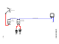
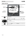
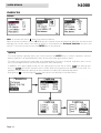
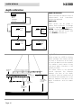
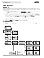
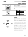
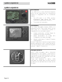
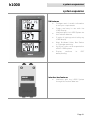
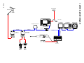
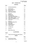
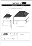
h1000 system
user manual
HB-1000D-02 English
WARNING!
Use of solvent based or chemical
cleaners on displays will result in
damage
and
invalidate
your
warranty.
introduction
Page 2
h1000
h1000
introduction
overview
Congratulations on your pu rchase of the h1000 System from B&G. The h1000 navigation system
combines clever thinking with incredibly simple operation, and represents B&G’s commitment to
providing customers with the finest marine navigation systems. The h1000 is a fully expandable
integrated system of Pilot, Instrument and Chart Plotters offering a major advance in display
flexibility. You can access any information from any display unit, so even one display unit can do
everything providing the sensors are in the system.
Before you begin using your new h1000 System, please take the time to read this manual to help
you achieve the full poten tial from your new system.
Page 3
introduction
h1000
certification
warnings and precautions:
WARNING:
DO NOT USE AN ALCOHOL BASED CLEANER ON THIS DISPLAY.
Note:
This equipment generates, uses, and can radiate radio frequency energy and, if not installed and
used in accordance with the instructions, may cause harmful interference to radio
communications. However, there is no guarantee that interference will not occur in a particular
installation. If this equipment does cause h armful interference, the user is encouraged to try to
correct the interference by relocating the equipment or connecting the equipment to a different
circuit. Consult an authorised dealer or oth er qualified technician for additional help if these
remedies do not correct the problem.
This device meets requirements for CFR47 Part 15 of the FCC limits for Class B equipment.
The h1000 meets the stan dards set out in European Standard EN 60945: 1997 IEC 945: 1996 for
maritime navigation and radiocommunication equipment and systems.
During the manufacturing process, an anti-mist coating is applied to the insi de of the display
window, however, un der certain atmospheric con ditions, a small amount of condensation may form
on the win dow of the instrument display, this will not harm the unit and should clear after a short
period once the instrument has been switched on
The h1000 contains no user-serviceable parts. Repairs should only be made by an authorised
service centre. Unauthorised repairs or modifications will invalidate your warranty.
trademarks
All rights reserved. No part of this manual may be reproduced or transmitted in any form or by any
means including photocopying and recording, for any purpose without the express written
permission of B&G.
Information in this document is subject to change without notice. B&G reserves the right to change
or improve its products and to make changes in the content without obligation to notify any person
or organisation of such changes.
B&G, and h1000 are all trademarks of Brookes & Gatehouse Ltd. and may not be used without the
express permission of B&G.
Page 4
h1000
contents
contents
overview
3
warnings and precautions
4
trademarks
4
contents
5
system overview
7
display overview
light controls
8
8
switching on and off
switching on
default data pages
examples of the default data pages
switching off
9
9
9
9
9
default factory settings
10
changing screen format
screen formats
changing page data
10
10
10
graphical pages
graphical pages
track screen
depth
pilot display
11
11
11
11
11
main menu
12
timer
12
memories
compass
reset trip log
alarms
13
13
13
13
memories
alarms
lighting
14
14
14
calibrations
15
depth calibration
16
speed calibration
17
Page 5
h1000
contents
contents
Page 6
wind calibration
19
compass calibration
21
system set-up
23
compass function
24
alarms
alarm conditions
error conditions
data failure
25
25
25
26
technical specifications
27
installation
precautions
panel mounting
28
28
28
electrical connections
external connections
29
29
interface connections
connections
29
29
system expansion
pilot features
cnd features
analogue features
30
30
30
30
system expansion
3fd features
interface box features
31
31
31
system expansion diagram
32
abbreviations
33
warranty
34
h1000
Masthead Unit
LCD Display
2m Fastnet Cable
Wind
Interface Box
10m Fastnet Cable
Speed Depth
Interface Box
12 Volts
Page 7
overview
Speed
Sensor
system overview
Depth
Sensor
h1000
overview
display overview
Title Line
Highlighted
Menu Item
Data Entry Field
Additional
commands are
displayed here
OK returns to
previous menu
when highlighted
and the ENTER
key is pressed
light controls
The lightin g level can be changed at any time by pressing the LIGHTS key.
This causes the lighting level to cycle in the sequence high - medium low - off and then back to high.
The UP/DOWN keys are used to move through the various display pages
and to scroll through options.
Pressing the ENTER key displays the Main Menu, it is also used to select
highlighted items.
Page 8
h1000
getting started
switching on and off
Before switching the h1000 on, check that the
installation instructions detailed on pages, 28 an d 29
have been correctly followed.
switching on
Turnin g on the 12 Volt power supply to the system you
will be presented with the B&G logo splash screen.
The h1000 will then perform a short self-test
procedure that checks internal memory and displays
any failure detected on th e screen.
After a few secon ds, the screen will display a data
page, from here you can move through the page
options using the UP/DOWN keys.
default data pages
The h1000 displays are pre-programmed with six
default data page formats. These can be accessed by
pressing the UP/DOWN keys. To change the default
data page settings; refer to changing screen format on
Page 7 of this manual. The flexibility of the h1000
system allows for a virtually endless combination of
screen formats to suit individual needs.
▲▼
▲▼
Stored Log
▲▼
▲▼
▲▼
▲▼
examples of the default data pages
switching off
Turnin g off the 12V d.c. power supply at the breaker
will power off the h1000 System.
Page 9
h1000
getting started
default factory settings
Language:
English
Speed/Distance Units:
Nautical Miles
Depth Units:
Metres
Wind Speed Units:
Knots
Bearing Reference:
Magnetic
Date Format:
Day-Month-Year
Time Reference:
UTC (universal time coordinate)
changing screen format
screen formats
The display can be customised for
preferences using the Page Contents menu.
personal
changing page data
Pressing the ENTER key from a data page will display the main menu. Select the Page Contents
menu and press ENTER to select the screen format of the data page previously displayed.
Choose one of the pre- defined screen formats using the UP/DOWN keys and then press ENTER to
select.
Once a screen format has been selected, use the UP/DOWN keys to select which pane you wish to
configure and press ENTER. Use th e UP/DOWN keys to scroll through the ‘information displayed’
choices and then press the ENTER key to select. Use the UP/DOWN keys to scroll to the next pane
and press ENTER to select th e pane.
Repeat the selection process until you have made a choice for each pane. Use the UP/DOWN keys
to highlight OK and press the ENTER key to save your selections.
To exit this function, use the UP/DOWN keys to highlight OK in the bottom right hand corner of the
screen an d press ENTER, you will then be taken back to th e Main Menu.
Page 10
h1000
getting started
graphical pages
graphical pages
There are three full-screen graphical pages available
when the appropriate data is on the system.
These pages are viewed by selecting Page Contents
from the Main Menu, and then selecting the Full
Screen option from the Select Format page.
track screen
Available when a GPS is part of the system and
currently navigating to an active waypoint.
The track screen shows the vessel’s position on the
screen as an X, the arrow from the vessel’s position
shows the current course over ground to the next
waypoint of the leg.
The relative position of the waypoint is shown as a
circle. The name of the waypoint, the bearing to
waypoint (BTW) and distance to waypoint (DTW)
information are also displayed. The position of this
information depends on the direction of the vessel.
depth
Available when a Depth sensor is part of the system.
Depth is clearly shown in figures in the top half of the
screen.
The histogram in th e lower half the screen gives an
impression of the profile of the seabed.
pilot display
Available when a Pilot is part of th e system.
This is a read-only repeat of the main page on the pilot
display unit.
The layout of this page will depend on the mode
currently selected by the pilot. Refer to the h1000 Pilot
User manual for more details.
Page 11
h1000
main menu
main menu
menu system
From any data page, press the ENTER key to access
the h1000 menu system. The Main Menu will be
displayed.
If no other key is pressed within a period of six
seconds, the display will revert to the previously
displayed data page.
timer
timer
When the Timer is selected from the Main Menu for the first time, the display will show Time to
Start. To adjust the start time, highlight 00 mins and press the ENTER key. Alter the countdown
start time by using the UP/DOWN keys and press the ENTER key to move between the digits.
To start the timer, use the UP/DOWN keys to highlight Start and press the ENTER key when ready.
If the timer is counting down to the start of a race, th e Title will remain as Time to Start. When the
timer reaches zero, the title will change to Elapsed Time and continue counting up until Reset is
selected.
The timer function continues to operate even when the timer page is exited. This allows access to
other pages if necessary or perhaps even configure a data page to show the Timer functi on.
Page 12
h1000
memories
memories
memories
This menu covers various features of the
system in which user-supplied data is stored
for future use.
compass
The compass memory holds the current course and can be user defined. Port and Starboard courses
are retained and are updated at each E NTER key press whilst in the Tactical compass page. When OK
is selected control returns to the Main Menu.
reset trip log
Trip log and Stored log functions can be accessed and displayed from the Page Contents menu when
a Speed/Depth Interface is connected to the system. The trip log can be reset to zero by highlighting
Reset trip log from the Memories Menu, selecting OK from the drop down box, and then pressing the
ENTER key. Choosing cancel from the drop-down box will exit the function without resetting the trip
log value.
alarms
Alarm levels for high wind speed, shallow depth, compass off course and low battery volts can be set
from the Alarms menu.
To set the wind speed alarm, highlight Wind speed from the menu and press the ENTER key. A dropdown box will appear sh owing an alarm wind speed value and off. To set the alarm, select the wind
speed value from the drop down box and press the ENTER key. Using the UP/DOWN and ENTER
keys, alter the value to the desired setting. The alarm is now active and will trigger if the win d speed
is exceeded. To switch off the alarm, simply highlight off from the drop-down box.
The procedure for setting the wind speed alarm is shown on the followin g page as an example. The
other alarms are set in a similar way.
Note: The low battery alarm is pre-set at 10.5V, and can only be turned ON or OFF.
Page 13
calibrations
h1000
memories
alarms
Note: all alarms are set to off when they leave the factory.
When an alarm condition occurs, all displays will show an alarm window that identifies the alarm and
displays the current value. If an external alarm is connected to the Universal Interface, this will also
sound. To silence the alarm press the ENTER key on any display.
lighting
The three display lighting levels are controlled by the LIGHTS key in normal operation, but the
exact brightness can be adjusted for each of the three settings from this menu.
The levels are numbered in the order they appear when the key is pressed, and each level can be
set in percentage terms from 00% (minimum) to 99% (maximum).
In addition, this menu page allows for the lighting zon e to be set to either local (this display unit
only), or system (the entire system) and is useful when zoning particular displays on the boat. For
example, cockpit display lighting can be isolated from a display located below decks.
Highlighting OK and pressing the ENTER key returns the display to th e Main Menu.
Page 14
h1000
calibrations
calibrations
calibration
Calibration values take time and effort to set up and it is often necessary to perform various
manoeuvres with the boat. For this reason , an optional security lock is provided before entry into
the Calibration Menu to prevent accidental resets.
security pin
The security PIN uses a four di git Personal Identification Number or PIN. If security has been
activated, this PIN must be entered if you require the Calibrations Menu.
If you reset the PIN to 0000, security checking is disabled.
security
Security is an option on the Calibrations menu, which allows a new PIN to be set. Once a non-zero
PIN has been set the security checking is enabled, and all subsequent access to the Calibration
Menu is restricted.
Note:
Once the PIN has been entered, the PIN entry screen is automatically by-passed when re-entering
the calibration menu. After a power cycle, the PIN is once again required to enter the Calibration
Menu.
Security
disabled
Security
enabled
Page 15
h1000
calibrations
depth calibration
depth calibration
C a libr a tio n
D e ppth
De
th
Speed
W in d
C o m p ass
S e curity
Depth calibration allows the units of
measurement
and
transducer
offset to be adjusted.
OK
depth units
D ep th C a lib r a tio n
D ep th C a lib r a tio n
Unit
U nit
O ffse t
Unit
U nit m e tre
O ffse t 1 .2 0
meetre
m
tre
1.2
0
fo ot
fa thom
OK
Depth values can be shown in
metres, feet or fathoms. To change
the units, highlight Unit and press
ENTER. Using the UP/DOWN keys,
highlight the desired choice and
press ENTER to memorise.
OK
D ep th C a lib r a tio n
U nit
Offse
O ffse tt
D ep th C a lib r a tio n
m e t re
1 .20
U nit
Offse
O ffse tt
OK
m e t re
1 .2 0
OK
depth offset
Offset allows the h1000 to display
depth readings from directly below
the keel or propellers of the boat,
or from the waterline to the seabed.
This makes it much easier to see
how much water clearance is left
beneath the boat.
WATERLINE
OFFSET
DEPTH
TRANSDUCER
KEEL
OFFSET
OFFSET
(VALUE OF
0.0)
KEEL
(- VE OFFSET
VALUES)
Page 16
WATERLINE
(+ VE OFFSET
VALUES)
The offset value to be entered
should represent the distance
between the face of the depth
transducer, and the lowest part of
the boat below the waterline, or the
distance between the face of the
depth transducer an d the water
surface.
h1000
calibrations
speed calibration
speed calibration
Speed calibration sets the units of measurement, damping and speed calibration factor (Refer to the
flow chart detailed on Page 18).
units
Boat speed values can be shown in knots, kph or mph. To change the units, highlight Unit and press
ENTER. Using the UP/DOWN keys, highlight the desired choice and press ENTER to memorise.
damping
Boat speed damping allows you to slow down the response of speed- readings in rougher conditions
by adjusting the damping value from 0 to 9. For minimum damping, set the value to 0, for maximum
damping, set the value to 9.
adjustment
Speed adjustment calibration is necessary to compensate for hull shape and paddlewh eel location on
your boat. For accurate speed and log readings, it is essential that the paddlewheel is calibrated.
adjustment - auto
This procedure will automatically calibrate the boat speed and log readings, and is the recommended
method for most boats. This procedure requires the boat to make consecutive runs, under power at a
constant speed, over a known distance.
Select two markers that are easily identifiable on the ground and on a chart, and where the effects of tidal
flow are at a minimum. Measure and record the distance between the markers on the chart.
It is recommended that three runs are carried out, this accounts for tidal efforts, and improves accuracy.
However, a time should be selected when the current is at a minimum, i.e. slack water between tides.
1) From the Speed Calibration Menu, highlight Adjustment , choose auto from the drop-down box, and
then press the ENTER key to confirm.
2) If necessary, adjust the Run Length to correspond with your measured distance and then highlight OK,
and press ENTER to accept.
3) The display will now show Run 1 and start will be highlighted. Maintaining the boat at your constant
speed, press ENTER when the boat is in line with the start of your measured distance. The display will
now change to show Run 1 with end highlighted.
4) When the boat is in line with the second marker of your measured distance, press the ENTER key to
temporarily halt the calibration. Run 2 and start will now be shown on the screen.
5) Maintaining your constant boat speed, turn the boat through 180° in preparation for your second run
along the measured distance. When the boat is in line with the second marker, press the ENTER key to
resume the calibration procedure. The display will now show RUN 2 and end will be highlighted.
6) When the boat is in line with the first marker, press the ENTER key. This will temporarily halt the
calibration procedure.
7) Repeat the procedure detailed above for Run 3 .
8) Upon completion of Run 3, highlight accept all and press ENTER. The system will now automatically
calculate the new boat speed and update the readings accordingly.
Note: If for any reason during the calibration procedure you wish to abort the calculation, simply
highlight abort all an d press the ENTER key.
Page 17
calibrations
h1000
speed calibration
adjustment – ref
Reference speed adjustment, allows for quick and easy calibration of your boat speed readings against a
known calibrated source; for example, speed over the ground from a GPS or alongside another boat with
a calibrated log.
1)
From the Speed Calibration Menu, highlight Adjustment, select ref from the drop-down box and
press ENTER to select. The display will now show the Reference Speed page.
2)
If Speed Over the Ground data is available on the system from a GPS, the h1000 will
automatically detect this and display this value on the screen with the message from SOG. To
accept this value, simply highlight the speed value shown, press the ENTER key repeatedly to
scroll past the di gits, use the UP/DOWN keys to select OK and press the E NTER key.
3)
If speed over the ground is not available, simply highlight th e speed value and, usin g the
UP/DOWN and ENTER keys, adjust the value to the known reference boat speed.
4)
Next, highlight OK and press ENTER to complete the operation.
sea temperature units
Sea temperatu re information can be shown in °c or °f. To ch ange the units, highlight Sea temp and
press ENTER. Using the UP/DOWN keys, highlight the desired choice, and press the ENTER key to
memorise.
Page 18
h1000
calibrations
wind calibration
wind calibration
Wind calibration sets the wind speed measurement units, damping, and masthead unit offset. The
masthead unit offset can be adjusted while observing the live apparent wind angle on the same page
(Refer to the flow chart detailed on Page 20).
wind speed - units
Wind speed values can be shown in knots, kph, mph or m/s. To change the wind speed units,
highlight Wind speed from the Calibration Menu and press ENTER. Next, highlight Unit, press
ENTER and select th e desired choice from the drop- down menu. Press th e ENTER key again to
memorise the setting.
wind speed damping
Wind speed damping allows you to slow down the response of wind speed-readings in gusty
conditions by adjusting th e damping value from 0 to 9. For minimum damping, set the value to 0.
Increase the damping value if the readings are too unstable in rough weath er.
wind angle - calibration
Accurate wind angle readings require the masthead unit to be installed facing forward and as close
to the centre line of the boat as possible. However, this is not always possible, so the h1000 allows a
masthead unit sensor offset to be applied. This offset applies an electronic correction so that wind
angle readings are then shown correctly on the display.
MHU offset is calculated by the following procedure:
1.
Sail close-hauled on a Port Tack and note the set of all sails. When conditi ons are steady, note
the apparent win d angle. For example, Port 35°.
2.
Tack the boat until close-hauled on a Starboard Tack, ensure the sails are set as for the Port
Tack. When conditions are steady, note the apparent wind angle. For example, Starboard 25°.
3.
To calculate the MHU Offset subtract the Starboard value from the Port value, then divide by
two.
For
example,
Port
35°
Starboard
25°
=
10
/
2
=
5.
If the value is positive the offset is to Port, if the value is negative it is to Starboard.
To enter the masthead unit offset, highlight Wind angle from the Wind Calibration Menu and press
ENTER to select. Highlight MHU offset and press ENTER.
If the value calculated is positive, the wind sensor is misaligned to Port. To correct this, the value
must be offset clockwise (starboard) by the value calculated. Use the UP/DOWN keys and the ENTER
key to alter the value.
If the value is negative, the wind sensor is misaligned to Starboard. To correct this, the readings must
be offset anti-clockwise (Port) by th e calculated value. Use the UP/DOWN keys and the ENTER key to
alter the value.
wind angle - damping
Wind angle damping allows you to slow down the response of wind angle readings in gusty conditions
by adjusting the damping value from 0 to 9. For minimum damping, set the value to 0. Increase the
damping value if the readings are too unstable in rough weather.
Page 19
calibrations
wind calibration
Page 20
h1000
h1000
calibrations
compass calibration
compass calibration
The Compass Calibration Menu sets the heading offset, damping, and swing parameters for the
h1000 fluxgate compass (Refer to the flow chart detailed on Page 22).
compass offset
The compass offset electronically compensates for fixed errors (misalignment) between the fluxgate
sensor and the direction of the boat. These errors can occu r if the compass sensor is not exactly
orientated durin g installation.
To accurately enter a compass offset, the boat’s actu al heading must be known, for example:
reference the h1000 fluxgate against a calibrated bowl compass, or follow a known transit referenced
from a chart.
To enter the compass offset value, highlight Compass from the Compass Calibration Menu and
press ENTER. Adjust the value using the UP/DOWN and ENTER keys. The value entered shoul d be
between +180° and -180°.
Example:
•
Boat’s actual heading is 076°
•
h1000 display shows 092°
•
The compass offset entered would be -016°
To facilitate this procedure, live heading is shown on the screen so that the effects of the offset can
immediately be seen.
compass damping
Compass damping allows you to slow down the response of compass readings in rougher weather by
adjusting the damping value from 0 to 9. For minimum damping, set the value to 0. Increase the
damping value if the readings are too unstable in rough weather.
compass swing
The swing procedure allows the compass to learn the effects of any magnetic deviation errors that
are unique to your boat. The swin g should be performed out in open water, on a calm day, with
minimal wind and waves, an d away from traffic, which may require th e procedure to be aborted.
The swing procedure requires the boat to be turned through a complete 360°, at a speed of less than
5 knots, at about 2° per second. The entire process should take about three minutes to complete.
To swing the compass, highlight Swing and press ENTER. The Compass Swing page will now be
displayed with start highlighted. With the boat settled on its turn, press the ENTER key to start the
swing.
The display will now show two bargraphs. The first is the Progress indicator, which will fill
completely after the boat has been tu rned through 360°. The second is the Turn rate indicator, which,
for optimum results, should n ot be allowed to fill completely.
After completion of the swin g, the message passed or failed will be shown. At any stage durin g the
swing, the procedure can be aborted by selecting abort and pressing the ENTER key.
Page 21
calibrations
compass calibration
Note: passed is
shown under the
Swing title when a
successful compass
swing has been stored
Page 22
h1000
h1000
system
system set-up
system set-up
The system menu configures parameters that affect the system as a whole.
Remote unit setup
Remote unit setup allows configuration of units in the system that do not have a keyboard; for
example, 3FD’s, Analogue meters and Universal Interface boxes.
3FD setup
Select 3FD from the Remote Units page and press ENTER to select. If more than one 3FD is
connected to the system, select the appropriate 3FD and observe which unit flashes.
Select the functions that are to be displayed on each of the three LCD windows from the list of
data options displayed. Highlighting OK and pressing ENTER confirms your selection. Scroll
between the three screens until all selections are made.
Analogue setup
Select the appropriate display, the analogue display pointer will wiggle to indicate it has been
selected. The only function of the analogue display, which is user configurable, is the lighting
level.
Selectable NMEA sentences
Identify the Universal Interface Box you wish to configure, this is identified by the first three
digits of the serial number found on the printed label located inside the lid of the interface box.
Select the chosen box from the list displayed, select either NMEA in or NMEA out. The options
available are detailed as follows:
Current Input - Press ENTER to select, press ENTER again and scroll through the listed
sentences, press ENTER to view the options. Press ENTER and scroll to either On or Off, press
ENTER to make your selection. Scroll to OK to return to the listed sentences. Repeat the
operation until you have made all your selections.
Current Output - Follow the same procedure as detailed above.
Name - Press ENTER to re-name the interface box (if required), use the UP/DOWN arrow
keys to select the number or letter required (maximum 10 characters), once you have
completed your name chan ge scroll to, and highlight OK, press ENTER to return to the
Remote units screen .
Heading ref
The system switches between true and magnetic headings to set the value of magnetic variation.
Note : If magnetic variation is available via NMEA that value will take precedence over anything
entered by the user.
Language
Displays a choice of five languages to select. Highlight the language of your choice, press ENTER
then highlight OK to retu rn to the System menu.
Diagnostics
Highlighting an option from the list will display information on Serial number, Software version,
Status and Network Node number. The diagnostic information page is read-only.
Page 23
h1000
system
system set-up
Contrast
Highlighting Contrast from the System menu and pressing ENTER will display the control bar for
contrast alterations. Highlight the control bar and press ENTER again, then using the UP/DOWN
arrow key adjusts the contrast to the desired level. Press ENTER once more to confirm your setting
then scroll to highlight OK, press ENTER to return to System page.
compass function
tactical compass display
When a compass an d a wind sensor are connected to the
system, the Tactical Compass function becomes available as a
full-page display option.
After a tack or gybe, an d the yacht is sailing a steady course,
press the ENTER key to store the displayed heading. Note, to
access the Main Menu from the Tactical Comp ass page, press
and hol d the ENTER key for two secon ds.
Any deviation from the stored course is shown on the screen as
a lift or head with the corresponding number of degrees. Lift is
always shown on the windward side of th e display and head on
the leeward.
storing the course
When the ENTER key is pressed whilst the Tactical Compass
page is displayed, the present heading is automatically stored
and the head / lift trend function reset. When this is done, the
display overlays the Heading with Course stored for two
seconds, as shown in the diagram, and the head or lift legends
disappear. As soon as heading deviates from the new stored
value, head or lift will be displayed with the number of degrees
as appropriate. Resetting the stored course also updates the
Course memory foun d under the Memories → Compass menu.
last tack information
When a tack occurs, the head / lift field in the bottom left or
right of the display is replaced with the last heading for that
tack, providin g it was previously stored by pressing th e ENTER
key.
Last tack heading remains on screen until the ENTER key is
pressed. When ENTER is pressed, Last Tack information
disappears, Course Stored is then shown for two seconds, and
then the appropriate head or lift information is shown.
Page 24
h1000
alarms
alarms
As well as responding to user input the display also
shows information about external events reported
over the network and allows the user to respond.
There are three types of external event:
Alarm conditions
Error conditions
Data failure
alarm conditions
Alarm conditions arise when a measured parameter
moves outside a range of set values.
The h1000 unit that is the source of the out of range
data detects the condition and broadcasts an alarm
message, which initiates the following sequence of
events:
All displays respond by showing a flashing alarm
overlay window.
Pressing any key on the display broadcasts the
alarm silence message.
On receipt of the alarm silence message, all other
displays remove the alarm overlay window and
revert to their previous displayed page.
The display that broadcast the alarm silence
message stops flashing the alarm overlay window,
and continues to display the curren t value of the
alarming function un til the user presses the ENTER
key, reverting the system to the previous display.
error conditions
An error con dition arises when an h1000 unit detects
an internal malfunction or when an outside element
behaves inconsistently (for example, if the autopilot
sends a rudder drive sign al but fails to detect any
resulting rudder movement).
The unit that detects either type of problem
broadcasts an error message and the displays
respond by showing an error overlay window. This
contains a description of the problem, and may
suggest a solution.
When any key is pressed on any display, an error
acknowledgement message is broadcast by the
display, and all displays revert to normal operation.
Page 25
h1000
alarms
alarms
data failure
While the system is running, each display keeps a
timer for each individual data type that it is currently
monitoring. Th e timer is reset whenever a network
message with that data type is received, so if no data
has been received for ten seconds or more the data
type is marked as havin g failed.
If data of that type is not currently displayed it will be
shown as ‘OFF’.
Page 26
h1000
technical specifications
technical specifications
• Dimensions:
110mm x 110mm
• Power consumption:
50mA = approx 1 BEN (Max. 60 BEN per System)
Digital Display
3 BEN
Analogue Display
2 BEN
Speed/Depth Interface Box
3 BEN
Wind Interface Box
1 BEN
Universal Interface Box
1 BEN
3FD
3 BEN
CND
1 BEN
Pilot Head
4 BEN
Pilot Processor
2 BEN
Compass
1 BEN
• NMEA Interface:
NMEA 0183 ver. 2.3
• Display:
LCD Panel FSTN
• Display Resolution:
120 x 80 pixels
• Temperature range:
-10/+60 degrees Celsius
• Memory:
Non-volatile-EEPROM
• Keyboard:
Silicon rubber, backlit
• Weight:
950g
• Accessories:
Flush mounting kit + mountin g template
Power supply an d I/O cable
Protective cover
Page 27
h1000
installation
installation
precautions
To avoid electromagnetic interference, it is
recommended that the h1000 Display be
installed no less than 0.3 metres from a
compass and 1 metre from the GPS.
The h1000 Display is Waterproof to IP67. Use
the cover when n ot in use. The rear connectors
that are not connected to cables must remain
protected by thei r appropriate caps.
panel mounting
Ensure the panel is flat and that there is sufficient room behind the panel to accommodate the
fixings an d connections, and using the template supplied, cut a hole in th e panel in the desired
position.
Fix the mounting bracket into the hole using the screws supplied.
Note: The sealing ring is fitted to the unit during manufacture. Its purpose is to prevent moisture
penetration and reduce the effects of any vibration transmitted through the instrument panel.
Press the Display into the mounting bracket; an audible ‘click’ will indicate that the case is
correctly located.
Secure the unit to the instrument panel by fitting the studs and thumbnuts su pplied.
Caution: To avoid damaging the casing, fixin g studs must only be tightened ‘finger-tight’.
Mounting
Bracket
Display
Unit
Sealing Ring
(Fitted at Manufacture)
Sun Cover
Page 28
h1000
installation
electrical connections
external connections
Two Fastnet² connectors are provided at the rear
of the unit. These connectors allow connection to
the rest of the system for the supply of power and
data.
2
3
Pin
Number
Functi on
1
12V
2
Busy
3
Fastnet²-
4
Fastnet²+
5
0V
5
1
4
Front view of
male connector pins
interface connections
connections
System components share data together via a
common Fastnet2 databus and are supplied with
bayon et connectors for ease of installation.
Selections of cable lengths are available with
options for straight an d right angle connectors to
suit most requirements.
Fastnet2
Cable
Fastnet2
Cable
HUB
12V Power
Cable
Fastnet2
Cable
To prevent the occurrence of voltage drops on
larger systems, the power supply to the system
should either be placed mid-way or at both en ds of
the Fastnet2 databus. To connect power to the
mid-point of the system, it is recommended that
the four-way Hu b be used. The four-Way Hub
offers two advantages. The first advantage is that it
offers a convenient entry point for power onto the
system. The second advantage is that it
conveniently allows the system to be branched to
reduce the overall length of the system. The
correct selection of Fastnet2 cable will negate the
need for any plugs to be removed from the system
and ensure years of faultless operation.
Page 29
h1000
system expansion
system expansion
pilot features
The h1000 Pilot is a fully functional Autopilot
which can be used either as a stand-alone
system or integrated into an instrument
system.
•
The LCD panel is an FSTN, positive,
transflective type having 120 pixels
horizontally and 80 pixels vertically
•
Three levels of Illumination
cnd features
The Central Navigation Display (CND) is a
waterproof colour Chart Plotter which can be
used either as a stand-alone system or
integrated into an instrument system.
•
Unique combination of Data Pages for
repeating instrument information
•
Latest presentation of C-Map
Cartography, hot-swap cartridges
•
Highest specification C-Map NT feature
implementation
NT+
Utilises C-Map User-Card technology to enable
backup of waypoints, tracks, routes and marks.
Also can be used for home route planning (with
optional C-Map PC-Planner Kit).
analogue features
B&G's h1000 Analogues add a distinctive
sophistication to any system - these easy to
read displays can be sighted anywhere they are
required to provide the helmsman and crew
with all necessary clear data.
Clarity and readability of B&G's h1000
Analogues has always been the best, favoured
by many for the ease with which trends can be
followed.
Page 30
h1000
system expansion
system expansion
3fd features
•
Configure each line with information
to suit your requi rements
•
Simple and easy to use with the
h1000 Display
•
Interfaces with the h1000 System via
the Fastnet² data bus
•
3 levels of lighting controlled by any
h1000 display
•
Mast, Bulkhead, Helm, Nav Station
or Flybridge mounting
•
Up to four units can be supported on
a B&G h1000 system
•
Display
conforms
waterproofing
to
IP67
interface box features
•
Interfaces with the h1000 System
through the Fastnet² data bus
Page 31
C ND
12v power
LCD Display
Pilot Display
Compass Sensor Unit
Analogue AWA
system expansion
Central Navigation Display
system expansion diagram
Page 32
GPS Antenna
Masthead Unit
0.5m
12v power
Fastnet2
Fastnet2
Fastnet2
Fastnet2
Speed Depth
Interface Box
Wind
Interface Box
Fastnet2
Fastnet2
Fastnet2
Hydraulic Ram T1-12V
h1000 acp
Rudder
Sensor
12v power
Speed
Sensor
h1000
Depth
Sensor
h1000
abbreviations
abbreviations
AWA = Apparent Wind Angle
Angle between boat’s bow an d the win d
measured across the deck
AWS = Apparent Wind Speed
The win d speed measured across the deck.
BRG = Bearing
It is the angle between the North (True or
Magnetic) and a destinati on. It represents the
direction to follow.
COG = Course Over Ground
Direction of the path over groun d actually
followed by a boat, derived from a GPS.
Current
Non-periodical
movement
of
seawater,
generally horizontal, due to many causes such
as different temperatures and prevalent winds.
Default
Indicates a value or a setting that is used if the
user has not defined a particular value.
Depth Contours
Imaginary lines connecting points of equal
water depth.
Depth Units
Sets the depth units between Ft = Feet, FM =
Fathoms and m = Metres. The default setting is
metres.
GPS = Global Positioning System
GPS is a satellite based navigation system
operated by the US Department of Defence. It
gives the navigator a position fix 24 hours a day,
365 days a year.
HDG = Heading
Compass directi on of boat.
SOG = Speed Over Ground
A calculation of the rate of movement of the
boat over th e ground, derived from a GPS.
TWA = True Wind Angle
Angle between boat’s heading and true win d
direction.
TWD = True wind Direction
Compass directi on of the wind.
VMG = Velocity Made Good
Performance measure of u pwind or downwin d
sailing.
Page 33
warranty
h1000
warranty
1. warranty
Brookes & Gatehouse Limited (“B&G”) warrants this product against defects in materials or
workmanship on the terms and con ditions set out below (the “Warranty”).
2. warranty period
The Warranty continues for 24 months from the date of purchase by the user (excluding mechanical
items, including but not limited to, autopilot drive units which are subject to 12 months warranty). It
is the user’s responsibility to demonstrate the date of pu rchase by showing a valid warranty card or
proof of purchase. If the user cannot do this, th e date of purchase shall be deemed the date of
manufacture as evidenced by the serial number on th e product.
3. repair and replacement
During the warranty period and subject to the terms and conditions set out below B&G will repai r
or, if it so chooses, replace the product. It is the user’s responsibility to arran ge and pay for
transport of the product back to B&G. B&G shall not be responsible for any such costs, including,
but not limited to:
3.1.
Boat slipping or lifting;
3.2.
Freight shipping charge;
3.3.
Engineer’s travelling time and expenses;
3.4.
Installation labour costs associated with the Warranty claims; and
3.5.
Loss or damage of products or boats in transit.
4. conditions
The Warranty will not apply in the following circumstances:
4.1.
4.2.
4.3.
4.4.
4.5.
Where the product has been installed in a manner or location other than that specified
in the installation instructions;
Where the product has been serviced or repaired by anyone other th an an authorized
representative;
Where the product has been used for purposes for which it is not inten ded;
Where the product h as been used in a manner other than that described in the manual
supplied; or
Where the damage is caused by exceptional even ts such as, but not limited to:
Abnormal levels of magnetic, electrical or acoustic interference;
o
Lightning strikes;
o
Accidents;
o
Intention al damage; or
o
Negligent use.
o
5. wear and tear
The Warranty is limited to defects in materials or workmanship an d does not cover normal wear
and tear such as (but not limited to) corrosion an d damage caused through the day to day running
of the boat.
Page 34
h1000
warranty
warranty
6. software
B&G shall not be liable under this Warranty or otherwise for any defect in software incorporated
within the product.
7. further warranties
The Warranty set out in this document is the only Warranty offered by B&G. B&G makes no further
promises in relation to this product such as (but not limited to):
7.1.
that it is suitable for any particular use; or
7.2.
that it conforms to any particular quality standards.
8. transfer
This Warranty is not transferable.
9. consequential loss
B&G shall not be liable for any damage to persons, yachts, equipment or any other property or for
any other kind of consequential loss.
10. governing law
This document is governed by and shall be construed in accordance with English law.
11. statutory rights
This Warranty is offered as an extra ben efit and does not affect your statutory rights against the
party who sold you the product.
Page 35