Download Installation and Service Guide, 2101 Model 200 - ps

Transcript
IBM Storage Solution Rack
2101 Model 200
Installation and Service Guide
SY27-7622-01
IBM Storage Solution Rack
2101 Model 200
Installation and Service Guide
SY27-7622-01
Note:
Before using this information and the product it supports, read the general information in “Safety and environmental
notices” on page vii, and “Notices” on page 43.
Second Edition (March 2005)
© Copyright International Business Machines Corporation 2005. All rights reserved.
US Government Users Restricted Rights – Use, duplication or disclosure restricted by GSA ADP Schedule Contract
with IBM Corp.
Contents
Figures . . . . . . . . . . . . . . . v
Safety and environmental notices . . . vii
Safety inspection procedure . . . . . . . . . vii
Laser safety . . . . . . . . . . . . . . ix
General restrictions . . . . . . . . . . . ix
Usage restrictions . . . . . . . . . . . ix
Environmental notices and statements . . . . . ix
Product recycling and disposal . . . . . . . ix
Battery return program . . . . . . . . . ix
About this book . . . . . . . . . . . xi
Who should use this book . . . .
Getting information, help, and service
Before you call . . . . . . .
Using the documentation . . . .
Web sites . . . . . . . . .
Software service and support . .
Hardware service and support . .
Fire suppression systems . . .
How to send your comments . .
.
.
.
.
.
.
.
.
.
.
.
.
.
.
.
.
.
.
.
.
xi
xi
xi
xi
. . . . . xii
. . . . . xii
. . . . . xii
. . . . . xiii
. . . . . xiii
Chapter 1. Installing the 2101 Model 200 1
Step 1. Positioning the rack . . . . . . . . . 2
Step 2. Leveling the rack . . . . . . . . . . 3
Step 3. Attaching the stabilizers . . . . . . . . 3
Step 4. Attaching the rack to a concrete floor . . . 4
Step 5. Attaching the rack to a concrete floor beneath
a raised floor . . . . . . . . . . . . . . 6
Step 6. Attaching the mounting plates . . . . . . 9
Step 7. Attaching the front door . . . . . . . . 9
Step 8. Checking the customer’s ac power source . . 10
Step 9. Connecting drawer and device cables . . . 11
Step 10. Powering on the system . . . . . . . 11
Chapter 2. 2101 Model 200 rack power
distribution . . . . . . . . . . . . . 13
Power distribution units
Type 6 PDU . . .
9188/7188 PDU . .
External ac power cords
Testing the PDU . . .
Safety notices . . .
Testing procedure .
(PDUs)
. . .
. . .
. . .
. . .
. . .
. . .
.
.
.
.
.
.
.
.
.
.
.
.
.
.
.
.
.
.
.
.
.
.
.
.
.
.
.
.
.
.
.
.
.
.
.
.
.
.
.
.
.
.
.
.
.
.
.
.
.
13
13
16
19
20
20
20
Chapter 3. Servicing the 2101 Model
200 rack . . . . . . . . . . . . . . 23
© Copyright IBM Corp. 2005
Safety notices . . . .
Power-on procedure .
Power-off procedure .
Removing and replacing
Removing the PDU .
Replacing the PDU .
Removing and replacing
Removing the door .
Replacing the door .
Relocating a rack . .
. . .
. . .
. . .
the PDU
. . .
. . .
the front
. . .
. . .
. . .
.
.
.
.
.
.
or
.
.
.
. .
. .
. .
. .
. .
. .
rear
. .
. .
. .
. .
. .
. .
. .
. .
. .
door
. .
. .
. .
.
.
.
.
.
.
.
.
.
.
.
.
.
.
.
.
.
.
.
.
23
23
24
24
24
25
25
25
26
26
Chapter 4. Parts information and
product specifications . . . . . . . . 29
Covers . . . . . . . . . .
Earthquake brace . . . . . .
Blank fillers . . . . . . . .
Power distribution unit (PDU) . .
Stabilizers . . . . . . . . .
Leveling feet . . . . . . . .
Power cords . . . . . . . .
2101 Model 200 rack specifications.
.
.
.
.
.
.
.
.
.
.
.
.
.
.
.
.
.
.
.
.
.
.
.
.
.
.
.
.
.
.
.
.
.
.
.
.
.
.
.
.
.
.
.
.
.
.
.
.
29
30
31
32
33
34
34
36
Hardware warranty . . . . . . . . . 39
Statement of limited warranty
Production status . . .
IBM warranty for machines
Warranty service. . . .
Extent of warranty . . .
Limitation of liability . .
.
.
.
.
.
.
.
.
.
.
.
.
.
.
.
.
.
.
.
.
.
.
.
.
.
.
.
.
.
.
.
.
.
.
.
.
.
.
.
.
.
.
.
.
.
.
.
.
39
39
39
40
40
41
Notices . . . . . . . . . . . . . . 43
Trademarks . . . . . . . . . . . . . .
Electronic emission statements . . . . . . . .
Federal Communications Commission (FCC)
statement . . . . . . . . . . . . . .
Industry Canada compliance statement . . . .
European community compliance statement . .
Germany compliance statement . . . . . . .
Japanese Voluntary Control Council for
Interference (VCCI) class 1 statement . . . . .
Korean Government Ministry of Communication
(MOC) statement . . . . . . . . . . .
Taiwan class A compliance statement . . . . .
43
44
44
44
44
45
46
46
46
Glossary . . . . . . . . . . . . . . 47
47
Index . . . . . . . . . . . . . . . 57
iii
iv
Installation and Service Guide, 2101 Model 200
Figures
1.
2.
3.
4.
5.
6.
7.
8.
9.
10.
Ground check . . . . . . . . . . . viii
Caster wheel . . . . . . . . . . . . 2
Leveling adjustments . . . . . . . . . . 3
Stabilizers . . . . . . . . . . . . . 4
Attaching the rack to a concrete floor . . . . 4
Leveling the rack . . . . . . . . . . . 6
Attaching the rack to a raised floor . . . . . 7
Leveling the rack . . . . . . . . . . . 8
Attaching the mounting plate . . . . . . . 9
Installing the front door . . . . . . . . 10
© Copyright IBM Corp. 2005
11.
12.
13.
14.
15.
16.
17.
Type 6 power distribution unit . . . .
Type 6 PDU ac diagram . . . . . .
Type 6 PDU to drawer or rack frame
grounding . . . . . . . . . . .
9188/7188 power distribution unit . . .
9188/7188 PDU ac diagram . . . . .
9188/7188 PDU to drawer or rack frame
grounding . . . . . . . . . . .
Removing the door . . . . . . . .
.
.
. 14
. 15
.
.
.
. 16
. 17
. 18
.
.
. 19
. 26
v
vi
Installation and Service Guide, 2101 Model 200
Safety and environmental notices
Safety notices are printed throughout this book.
A danger notice indicates the presence of a hazard that has the potential of causing
death or serious personal injury.
A caution notice indicates the presence of a hazard that has the potential of causing
moderate or minor personal injury.
An attention notice indicates the possibility of damage to a program, device,
system, or data.
Safety inspection procedure
Perform a safety inspection on the rack when any of the following conditions
occur:
v The rack is inspected under a maintenance agreement.
v Service is requested and service has not recently been performed.
v An alterations-and-attachments review is performed.
v Changes have been made to the equipment that might affect the safe operation
of the equipment.
v External devices with an attached power cord are connected to the rack.
Be cautious of potential safety hazards that are not covered in the safety checks. If
the inspection indicates an unacceptable safety condition, the condition must be
corrected before you can service the machine.
Note: It is the responsibility of the owner of the system to correct any unsafe
condition.
Do the following safety checks:
1. If the rack is bolted down, ensure that the rack is firmly secured to the floor.
See Figure 5 on page 4.
2. If the rack is not bolted down, ensure that the stabilizers are firmly attached
to both the bottom front and bottom rear of the rack. See Figure 4 on page 4.
CAUTION:
The stabilizer must be firmly attached to the bottom front and bottom rear
of the rack to prevent the rack from turning over when the drawers are
pulled out of the rack. Do not pull out or install any drawer or feature if
the stabilizer is not attached to the rack.
3. Check the covers for sharp edges and for damage or alterations that expose
the internal parts of the rack.
4. Check the covers for a proper fit to the rack. The covers should be in place
and secure.
5. Open the back door of the rack.
6. Perform the power-off procedure for the power distribution unit (PDU) that is
installed in the rack. See “Power-off procedure” on page 24 for power-off
procedures.
© Copyright IBM Corp. 2005
vii
7. Check for alterations or attachments. If there are any, check for obvious safety
hazards such as broken wires, sharp edges, or broken insulation.
8. Check the internal cables for damage.
9. Check for dirt, water, and any other contamination within the rack.
10. Check the voltage label on the back of the system unit to ensure that it
matches the voltage at the outlet.
11. Check the external power cable for damage.
12. Perform the following grounding checks:
a. With the external power cord connected to the system unit, check for 0.1
ohm or less resistance between the ground plug on the external power
cord plug and the metal frame. See Figure 1.
Rear View
L1
L1
L1
RT000015
Figure 1. Ground check
b. Using the appropriate probe, check for 0.1 ohm or less resistance between
the metal frame and the grounding pin on each of the power outlets on
each power distribution bus.
13. Check for the following conditions for each external device that has an
attached power cord:
viii
Installation and Service Guide, 2101 Model 200
v Damage to the power cord.
v The correct grounded power cord.
v With the external power cord connected to the device, check for 0.1 ohm or
less resistance between the ground lug on the external power cord plug and
the metal frame of the device.
14. Close the rear cover of the rack.
15. Perform the power-on procedure for the PDU that is installed in the rack. See
“Power-on procedure” on page 23 for power-on procedures.
Laser safety
This unit might contain a single-mode or a multi-mode transceiver class 1 laser
product which complies with IEC 825-1 and FDA 21 CFR 1040.10 and 1040.11. The
transceiver must be operated under the recommended operating conditions.
General restrictions
The classification of the laser is valid only if the module is operated within the
specified temperature and voltage limits. The system using the module must
provide power supply protection that guarantees that the system power source will
cease to provide power if the maximum recommended operation limit or more is
detected on the +3.3 V or the +5 V at the power source. The operating temperature
of the module must be in the temperature range given in the recommended
operating limits. These limits guarantee the laser safety.
Usage restrictions
The optical ports of the modules must be terminated with an optical connector or
with a dust plug.
Environmental notices and statements
This section covers product recycling and product disposal.
Product recycling and disposal
This unit might contain materials such as circuit boards, cables, electromagnetic
compatibility gaskets, and connectors which may contain lead and
copper/beryllium alloys that require special handling and disposal at end of life.
Before this unit is disposed of, these materials must be removed and recycled or
discarded according to applicable regulations. IBM® offers product-return
programs in several countries. Information on product recycling offerings can be
found on IBM’s Internet site at
www.ibm.com/ibm/environment/products/prp.shtml
IBM encourages owners of information technology (IT) equipment to responsibly
recycle their equipment when it is no longer needed. IBM offers a variety of
programs and services to assist equipment owners in recycling their IT products.
Information on product recycling offerings can be found on IBM’s Internet site at
www.ibm.com/ibm/environment/products/prp.shtml
Battery return program
This product may contain a sealed lead acid, nickel cadmium, nickel metal
hydride, lithium, or lithium ion battery. Consult your user manual or service
Safety and environmental notices
ix
manual for specific battery information. The battery must be recycled or disposed
of properly. Recycling facilities may not be available in your area. For information
on disposal of batteries outside the United States, see
http://www.ibm.com/ibm/environment/products/batteryrecycle.shtml or contact
your local waste disposal facility.
In the United States, IBM has established a return process for reuse, recycling, or
proper disposal of used IBM sealed lead acid, nickel cadmium, nickel metal
hydride, and battery packs from IBM equipment. For information on proper
disposal of these batteries, contact IBM at 1-800-426-4333. Have the IBM part
number listed on the battery available prior to your call.
In the Netherlands, the following applies.
For Taiwan: Please recycle batteries.
x
Installation and Service Guide, 2101 Model 200
About this book
This book provides installation and maintenance information that is specific to the
IBM 2101 Model 200 rack.
Who should use this book
This book is used by the service representative to install or repair the 2101 Model
200 rack.
Getting information, help, and service
If you need help, service, or technical assistance or just want more information
about IBM products, you will find a wide variety of sources available from IBM to
assist you. This section contains information about where to go for additional
information about IBM and IBM products, what to do if you experience a problem
with your IBM Eserver xSeries® or IntelliStation® system, and whom to call for
service, if it is necessary.
Before you call
Before you call, make sure that you have taken these steps to try to solve the
problem yourself:
v Check all cables to make sure that they are connected.
v Check the power switches to make sure that the system is turned on.
v Use the troubleshooting information in your system documentation and use the
diagnostic tools that come with your system.
v Check for technical information, hints, tips, and new device drivers at the
following Web site:
www.ibm.com/servers/storage/support/disk/
v Use an IBM discussion forum on the IBM Web site to ask questions.
You can solve many problems without outside assistance by following the
troubleshooting procedures that IBM provides in the online help or in the
documents that are provided with your system and software. The information that
comes with your system also describes the diagnostic tests that you can perform.
Most xSeries and IntelliStation systems, operating systems, and programs come
with information that contains troubleshooting procedures and explanations of
error messages and error codes. If you suspect a software problem, see the
information for the operating system or program.
Using the documentation
Information about the xSeries or IntelliStation system and preinstalled software, if
any, is available in the documents that come with your system. This includes
printed documents, online documents, readme files, and help files. See the
troubleshooting information in your system documentation for instructions on how
to use the diagnostic programs. The troubleshooting information or the diagnostic
programs might tell you that you need additional or updated device drivers or
other software.
© Copyright IBM Corp. 2005
xi
Web sites
IBM maintains pages on the World Wide Web where you can get the latest
technical information and download device drivers and updates.
v For DS4000 and DS6000 information, go to the following Web site:
www.ibm.com/servers/storage/support/disk/
The support page has many sources of information and ways for you to solve
problems, including:
– Diagnosing problems using the IBM Online Assistant
– Downloading the latest device drivers and updates for your products
– Viewing frequently asked questions (FAQ)
– Viewing hints and tips to help you solve problems
– Participating in IBM discussion forums
– Setting up e-mail notification of technical updates about your products
v You can order publications thrs of ough the IBM Publications Ordering System
at the following web site:
www.elink.ibmlink.ibm.com/public/applications/publications/cgibin/pbi.cgi/
v For the latest information about IBM xSeries products, services, and support, go
to the following Web site:
www.ibm.com/eserver/xseries/
v For the latest information about IBM pSeries® products, services, and support,
go to the following Web site:
www.ibm.com/eserver/pseries/
v For the latest information about the IBM IntelliStation information, go to the
following Web site:
www-132.ibm.com/content/home/store_IBMPublicUSA/
en_US/IntelliStation_workstations.html
v For the latest information about operating system and HBA support, clustering
support, SAN fabric support, and Storage Manager feature support, see the
TotalStorage® DS4000 Interoperability Matrix at the following Web site:
www.ibm.com/servers/storage/disk/ds4000/interop-matrix.html
Software service and support
Through IBM Support Line, for a fee you can get telephone assistance with usage,
configuration, and software problems with xSeries servers, IntelliStation
workstations, and appliances. For information about which products are supported
by Support Line in your country or region, go to the following Web site:
www.ibm.com/services/sl/products/
For more information about the IBM Support Line and other IBM services, go to
the following Web sites:
v www.ibm.com/services/
v www.ibm.com/planetwide/
Hardware service and support
You can receive hardware service through IBM Integrated Technology Services or
through your IBM reseller, if your reseller is authorized by IBM to provide
warranty service. Go to the following Web site for support telephone numbers:
xii
Installation and Service Guide, 2101 Model 200
www.ibm.com/planetwide/
In the U.S. and Canada, hardware service and support is available 24 hours a day,
7 days a week. In the U.K., these services are available Monday through Friday,
from 9 a.m. to 6 p.m.
Fire suppression systems
A fire suppression system is the responsibility of the customer. The customer’s own
insurance underwriter, local fire marshal, or a local building inspector, or both,
should be consulted in selecting a fire suppression system that provides the correct
level of coverage and protection. IBM designs and manufactures equipment to
internal and external standards that require certain environments for reliable
operation. Because IBM does not test any equipment for compatibility with fire
suppression systems, IBM does not make compatibility claims of any kind nor
does IBM provide recommendations on fire suppression systems.
How to send your comments
Your feedback is important in helping us to provide the most accurate and
high-quality information. If you have comments or suggestions for improving this
publication, you can send us comments electronically by using these addresses:
v Internet: [email protected]
v IBMLink™ from U.S.A.: STARPUBS at SJEVM5
v IBMLink from Canada: STARPUBS at TORIBM
v IBM Mail Exchange: USIB3WD at IBMMAIL
You can also mail your comments by using the Reader Comment Form in the back
of this manual or direct your mail to:
International Business Machines Corporation
Information Development
Dept. GZW
9000 South Rita Road
Tucson, AZ 85744–0001
U.S.A.
About this book
xiii
xiv
Installation and Service Guide, 2101 Model 200
Chapter 1. Installing the 2101 Model 200
This chapter contains the procedures for installing a 2101 Model 200 rack and
preparing it for operation. The 2101 Model 200 rack supports DS4000 and DS6000
series drawers.
The following safety notices apply to the procedures in this chapter. Review this
section carefully before installing the 2101 Model 200 rack.
DANGER
An electrical outlet that is not correctly wired could place hazardous voltage
on metal parts of the system or the devices that attach to the system. It is the
responsibility of the customer to ensure that the outlet is correctly wired and
grounded to prevent an electrical shock.
Before installing or removing signal cables, ensure that the power cables for
the system unit and all attached devices are unplugged.
When adding or removing any additional devices to or from the system,
ensure that the power cables for those devices are unplugged before the
signal cables are connected. If possible, disconnect all power cables from the
existing system before you add a device.
Use one hand, when possible, to connect or disconnect signal cables to
prevent a possible shock from touching two surfaces with different electrical
potentials.
During an electrical storm, do not connect cables for display stations, printers,
telephones, or station protectors for communication lines.
CAUTION:
This product is equipped with a 3-wire power cable and grounded plug for the
user’s safety. Use this power cable in conjunction with a properly grounded
electrical outlet to avoid electrical shock.
CAUTION:
This unit may have more than one power supply cord. To completely remove
power, you must disconnect all power supply cords.
© Copyright IBM Corp. 2005
1
CAUTION:
Make sure that you do the following:
v Before you add or remove drawers, always have the leveling feet lowered and
the front and rear stabilizer installed, or have the rack bolted to the floor.
v Always install drawers at the bottom of the rack first.
v Always remove drawers from the top of the rack first.
v Always install the heaviest drawers on the bottom of the rack.
v Remove two or three drawers from the top of the rack before you relocate it.
v Never push on the sides of the rack.
Attention: If the rack has equipment located above EIA location 32, you must
remove the equipment in position 32 and above from the rack before
you move it. Always remove the equipment from the top of the rack
first.
Step 1. Positioning the rack
Read before installing the 2101 Model 200 rack:
The IBM 2101 Model 200 rack requires installation by IBM. Some pre-installed
products might not require installation by IBM and could be customer set-up
(CSU). Check to see if the rack contains pre-installed CSU products, such as the
2106. Ask the customer if they have purchased installation services from IBM for
CSU products before installing anything more than the 2101 Model 200 rack itself.
Note: The customer should have unpacked the rack and positioned it in the room.
If this has not been done, you will need to do so before installing the rack.
1. If the customer has not unpacked and positioned the rack, do the following:
a. Remove all packing and tape from the rack.
b. Position the rack according to the customer floor plan.
2. Lock each caster wheel by tightening the screw on the caster. See Figure 2.
Locking Screw
RT000001
Figure 2. Caster wheel
Use the following to determine the next step:
v If the rack is not being attached to the floor, go to the next step.
v If the rack is being bolted to a concrete floor, go to “Step 4. Attaching the rack to
a concrete floor” on page 4.
2
Installation and Service Guide, 2101 Model 200
v If the rack is being bolted to a concrete floor beneath a raised floor, go to “Step
5. Attaching the rack to a concrete floor beneath a raised floor” on page 6.
Step 2. Leveling the rack
Complete the following steps to adjust the leveling feet:
1. Loosen the jam nut on each leveling foot by turning the nut counterclockwise,
away from the bottom of the rack. See Figure 3.
2. Rotate each leveling foot downward until it contacts the surface on which the
rack is placed.
3. Adjust the leveling feet downward as needed until the rack is level. When the
rack is level, tighten the jam nuts against the base by turning the nut clockwise,
toward the bottom of the rack.
Rear of Cabinet
Jam Nut
Leveling Screw
Front of Cabinet
RT000002
Figure 3. Leveling adjustments
Step 3. Attaching the stabilizers
CAUTION:
The stabilizers must be firmly attached to the bottom front and bottom rear of
the rack to prevent the rack from turning over when the drawers are pulled out
of the rack. Do not pull out or install any drawer or feature if the stabilizers are
not attached to the rack.
1. Align the slots in the stabilizer with the mounting holes at the bottom front of
the rack. See Figure 4 on page 4.
2. Install the two mounting screws.
3. Ensure that the base of the stabilizer rests firmly on the floor. Use the allen
wrench that is supplied with the rack to alternately tighten the mounting
screws until they are tight.
Chapter 1. Installing the 2101 Model 200
3
Front of Cabinet
Mounting Screw
Mounting Hole
Allen Wrench
Mounting Screw
Rear of Cabinet
Stabilizer
RT000003
Figure 4. Stabilizers
4. Repeat steps 1 through 3 to install the stabilizer at the bottom rear of the rack.
Step 4. Attaching the rack to a concrete floor
This procedure covers attaching the rack-mounting plates directly to a concrete
floor.
Refer to Figure 5 while completing these steps.
Note: The customer is responsible for attaching the rack-mounting plates to the
concrete floor. The following steps guide the customer in aligning and
installing the rack-mounting plates.
Mounting
Hole (4X)
Jam Nut (4X)
Leveler (4X)
Bolt (4X)
Washer (4X)
Bushing (8X)
Thick Washer (4X)
Tapped Hole for
Rack Mounting
Spacer (4X)
Hole for
Anchor Bolts
Mounting
Plate (2X)
Location
Mark (Drill)
RT000005
Figure 5. Attaching the rack to a concrete floor
1. Ensure that the rack is in the correct location.
2. In this rack, the bushings are temporarily installed to help position the
rack-mounting plates.
4
Installation and Service Guide, 2101 Model 200
3. Ensure that the bushing is in the leveling foot. Position the two rack-mounting
plates in the approximate mounting location under the rack. If necessary, raise
the leveling feet for clearance.
4. Place a bushing on a rack-mounting bolt. Insert the bolt and bushing through
the leveling foot and bushing and out the bottom bushing.
5. Insert the four rack-mounting bolts through the leveling feet and bushings,
and out the bottom of the rack.
6. Position the rack-mounting plates under the four rack-mounting bolts so that
the rack-mounting bolts are centered directly over the tapped holes.
7. Turn the rack-mounting bolts 3 - 4 turns into the tapped holes.
8. Mark the floor around the edges of both rack-mounting plates.
9. Mark the rack-mounting plate bolt-down holes that are accessible through the
opening in the rear of the rack.
10. Remove the rack-mounting bolts and bushings.
11. Remove the rack-mounting plates.
12. Loosen the locking screws on the casters, and move the rack so that it is clear
of the locator marks for the rack-mounting plates.
13. Position the rack-mounting plates within the marked areas.
14. Mark the floor at the center of each hole in the rack-mounting plates
(including the tapped holes).
15. Remove the two rack-mounting plates from the marked locations.
16. At the marked location of the tapped rack-mounting bolt holes, drill four
holes approximately 5 cm (2 in.) deep to allow clearance for the ends of the
four rack-mounting bolts. The ends of the rack-mounting bolts protrude past
the thickness of the mounting plate.
Note: You must use a minimum of two anchor bolts for each rack-mounting
plate to attach it to the concrete floor. Because some of the holes in the
rack-mounting plates might align with concrete reinforcement rods
below the surface of the concrete, some of the rack-mounting plate
holes might not be suitable.
17. For each rack-mounting plate, select at least two suitable holes. Select holes as
close to the threaded holes as possible. Be sure that the holes you select at the
rear of the rack are accessible. Drill the selected holes (two for each
rack-mounting plate).
18. Position the front rack-mounting plate within the marked area.
19. Using anchor bolts, attach the front rack-mounting plate to the concrete floor.
20.
21.
22.
23.
24.
Note: Do not use the four plastic isolator bushings.
Position the rack over the front rack-mounting plate.
Position the rear rack-mounting plate within the marked area.
Using anchor bolts, attach the rear rack-mounting plate to the concrete floor.
Insert each of the rack-mounting bolts through a flat washer, a thick washer,
and through a leveling foot.
Align the four rack-mounting bolts with the four tapped holes in the two
rack-mounting plates and turn the bolts 3 - 4 rotations.
25. Tighten the locking screw on each caster.
26. Adjust the leveling screw downward as needed until the rack is level. See
Figure 6 on page 6. When the rack is level, tighten the jam nuts against the
Chapter 1. Installing the 2101 Model 200
5
base by turning the jam nut clockwise, toward the bottom of the rack. Torque
the four bolts to 54 - 67 nm (40 - 50 ft-lbs).
Rear of Cabinet
Jam Nut
Leveling Screw
Front of Cabinet
RT000002
Figure 6. Leveling the rack
27. After all the racks are bolted down, go to “Step 6. Attaching the mounting
plates” on page 9.
Step 5. Attaching the rack to a concrete floor beneath a raised floor
Refer to Figure 7 on page 7 while completing these steps.
This procedure covers attaching the rack-mounting plates to the concrete floor
beneath a raised floor.
Note: The customer is responsible for attaching the rack-mounting plates to the
concrete floor. The following steps guide the customer in aligning and
installing the rack-mounting plates.
6
Installation and Service Guide, 2101 Model 200
Mounting
Hole (4X)
Jam Nut (4X)
Leveler (4X)
Bolt (4X)
Washer (4X)
Bushing (8X)
Thick Washer (4X)
Tapped Hole for
Rack Mounting
Spacer (4X)
Hole for
Anchor Bolts
Mounting
Plate (2X)
Location
Mark (Drill)
RT000005
Figure 7. Attaching the rack to a raised floor
1. Ensure that the rack is in the correct location.
2. In this rack, the bushings are temporarily installed to help position the
rack-mounting plates.
3. Ensure that the bushing is in the leveling foot. Position the two rack-mounting
plates in the approximate mounting locations under the rack. If necessary,
raise the leveling feet for clearance.
4. Place a bushing on a rack-mounting bolt. Insert the bolt and bushing through
the leveling foot and bushing and out the bottom bushing.
5. Insert the four rack-mounting bolts through the leveling feet and bushings,
and out the bottom of the rack.
6. Position the rack-mounting plates under the four rack-mounting bolts so that
the rack-mounting bolts are centered directly over the tapped holes.
7. Turn the rack-mounting bolts 3 - 4 turns into the tapped holes.
8. Mark the raised-floor panel around the edges of both rack-mounting plates.
9. Mark the rack-mounting plate bolt-down holes that are accessible through the
opening in the rear of the rack.
10. Remove the rack-mounting bolts and bushings.
11. Remove the rack-mounting plates.
12. Loosen the locking screws on the casters and move the rack so that it is clear
of the locator marks for the rack-mounting plates.
13. Position the rack-mounting plates within the marked areas.
14. Mark the raised-floor panel at the center of each hole in the rack-mounting
plates (including the tapped holes).
15. Remove the two rack-mounting plates from the marked locations.
16. Transfer the locations of the holes from the raised-floor panel to the concrete
floor directly beneath, and mark the holes there.
Chapter 1. Installing the 2101 Model 200
7
Note: You must use a minimum of two anchor bolts for each rack-mounting
plate to attach it to the concrete floor. Because some of the holes in the
rack-mounting plates might align with concrete reinforcement rods
below the surface of the concrete, some of the rack-mounting plate
holes might not be suitable.
17. For each rack-mounting plate, select at least two suitable holes. Select holes as
close to the threaded holes as possible. Be sure that the holes you select at the
rear of the rack are accessible. Drill the selected holes (two for each
rack-mounting plate) in the concrete floor.
18. Drill pass-through holes in the raised-floor panel at the location of the four
rack-mounting bolts.
19. Position the front rack-mounting plate within the marked area.
20. Using anchor bolts, attach the front rack-mounting plate to the concrete floor.
Do not use the four plastic isolator bushings.
Position the rack on the raised-floor panel over the front rack-mounting plate.
Position the rear rack-mounting plate within the marked area.
Using anchor bolts, attach the rear rack-mounting plate to the concrete floor.
Insert each of the rack-mounting bolts through a flat washer, a plastic isolator
bushing, a thick washer, and through a leveling foot.
25. Align the four rack-mounting bolts with the four tapped holes in the two
mounting plates and turn the bolts 3 - 4 rotations.
26. Tighten the locking screw on each caster.
27. Adjust the leveling feet downward as needed until the rack is level. See
Figure 8. When the rack is level, tighten the jam nuts against the base by
turning the jam nut clockwise (toward the bottom of the rack). Torque the
four bolts to 54 - 67 nm (40 - 50 ft-lbs).
21.
22.
23.
24.
Rear of Cabinet
Jam Nut
Leveling Screw
Front of Cabinet
RT000002
Figure 8. Leveling the rack
28. If the rack does not have a front door, install the top, left, and right trim
panels.
8
Installation and Service Guide, 2101 Model 200
29. After all the racks are bolted down, go to “Step 7. Attaching the front door.”
Step 6. Attaching the mounting plates
Note: You attach the front and rear mounting plates through the same mounting
holes that are used to mount the stabilizers. Therefore, the rack must be
bolted down rather than using the stabilizers. Install the mounting plates
only if the rack is bolted to the floor.
The mounting plates are part of the Earthquake Mounting Kit, feature code 6080.
Using the allen wrench that is supplied with the rack, align the holes on the
mounting plate with the holes on the front of the rack, and install the mounting
plate screws (stabilizer mounting screws). Repeat this procedure for the mounting
plate on the rear of the rack. See Figure 9.
Front of Cabinet
Mounting Screw
Mounting Plate
Allen
Wrench
RT000008
Figure 9. Attaching the mounting plate
Step 7. Attaching the front door
If necessary, complete the following steps to install the front door:
Chapter 1. Installing the 2101 Model 200
9
Latch Mounting Screws
Latch
Door Removed for Clarity
Hinge Mounting Screws
Hinges
Door
RT000022
Figure 10. Installing the front door
1. Install the hinges as shown in Figure 10.
2. Install the latch as shown in Figure 10.
3. Align the lower hinge pin on the front door with the hinge and partially insert
the pin into the hinge.
4. Align the upper hinge pin with the hinge and lower the door into position.
5. Adjust the latch so that the door is latched securely.
Step 8. Checking the customer’s ac power source
Before plugging the rack into the ac power source, do the following checks on the
customer’s ac power source.
CAUTION:
Do not touch the receptacle or the receptacle face plate with anything other than
your test probes before you have met the requirements in this step.
1. Have the customer turn off the branch circuit breaker for the ac power outlet
that the rack will plug into. Attach a ″Do Not Operate″ tag (S229-0237) to the
circuit breaker switch.
Note: All measurements are made with the receptacle face plate in the normal
installed position.
2. Some receptacles are enclosed in metal housings. For this type of receptacle, do
the following:
a. Check for less than 1 volt from the receptacle case to any grounded metal
structure in the building, such as a raised-floor metal structure, water pipe,
building steel, or similar structure.
b. Check for less than 1 volt from the receptacle ground pin to a grounded
point in the building.
10
Installation and Service Guide, 2101 Model 200
Note: If the receptacle case or face plate is painted, be sure that the probe
tip penetrates the paint and makes good electrical contact with the
metal.
c. Check the resistance from the ground pin of the receptacle to the receptacle
case. Check the resistance from the ground pin to the building ground. The
readings should be less than 1.0 ohm, which indicates the presence of a
continuous grounding conductor.
3. If any of the three checks that you made in step 2 on page 10 are not correct,
ask the customer to remove the power from the branch circuit and make the
wiring corrections; then check the receptacle again.
4.
5.
6.
7.
8.
Note: Do not use a digital multimeter to measure grounding resistance in the
following steps.
Check for infinite resistance between the ground pin of the receptacle and each
of the phase pins. This is a check for a wiring short to ground or a wiring
reversal.
Check for infinite resistance between the phase pins. This is a check for a
wiring short.
CAUTION:
If the reading is other than infinity, do not proceed! Have the customer make
the necessary wiring corrections before continuing. Do not turn on the
branch circuit breaker until all the above steps are satisfactorily completed.
Have the customer turn on the branch circuit breaker. Measure for the
appropriate voltages between phases. If no voltage is present on the receptacle
case or the ground pin, the receptacle is safe to touch.
With an appropriate meter, verify that the voltage at the ac outlet is correct.
Verify that the grounding impedance is correct by using the ECOS 1020, 1023,
B7106, C7106, or an appropriately approved ground impedance tester.
Step 9. Connecting drawer and device cables
Most racks are configured in the factory, with all drawer and device cables
installed.
If you need to install drawer and device cables, follow the installation instructions
provided with the component being installed. The 2101 Model 200 rack supports
DS4000 and DS6000 drawers and devices.
Attention: The power limitations of the PDU single-phase power cords limit the
number of drawers that can be plugged into a pair of PDUs. A maximum of six
drawers can plugged into a single pair of power distribution units (PDUs). If
you are installing and powering more than six drawers in a single rack, you must
install a second pair of PDUs (making a total of four PDUs) to support the
additional drawers. For more information, see Chapter 2, “2101 Model 200 rack
power distribution,” on page 13.
Step 10. Powering on the system
Follow the power-on procedure in “Power-on procedure” on page 23 for your type
of rack.
Chapter 1. Installing the 2101 Model 200
11
12
Installation and Service Guide, 2101 Model 200
Chapter 2. 2101 Model 200 rack power distribution
This chapter contains information about the 2101 Model 200 rack, the Type 6 and
9188/7188 ac power distribution units (PDUs), and the procedure to test the PDUs.
The 2101 Model 200 rack supports DS4000 and DS6000 drawers and devices.
Power distribution units (PDUs)
Power is distributed to the devices and drawers in the rack by power distribution
units (PDUs). PDUs must be installed in pairs. A rack is configured with either two
or four PDUs.
The 2101 Model 200 rack supports Type 6 PDUs and 9188/7188 PDUs.
v Type 6 PDUs have six IEC30–C13, 200 V to 240 V ac outlets. An additional two
front outlets have limited access, as shown in Figure 11 on page 14. The input ac
power to the PDU is not switched, so each outlet has a separate circuit breaker
to protect against excessive current. See Figure 12 on page 15. The type 6 PDU
feature codes are 6271 and 9271.
v 9188/7188 PDUs have twelve IEC30–C13, 200 V to 240 V ac outlets. See
Figure 14 on page 17. The input ac power to the PDU is not switched, so each
outlet has a separate circuit breaker to protect against excessive current. See
Figure 15 on page 18.
You can mix Type 6 PDUs and 9188/7188 PDUs within a single rack.
The Type 6 PDU and 9188/7188 PDU are described in the following sections.
Type 6 PDU
Each type 6 PDU contains eight 200 V - 240 V ac outlets that provide power to the
devices and drawers. See Figure 11 on page 14.
© Copyright IBM Corp. 2005
13
Rear View
View of Power
Distribution Unit
Facing Front of Rack
Power
Distribution
Unit
R7
CB7
R6
CB6
R8
CB8
R5
L1
L1
CB5
Outlets for
Peripherals
(Two Facing
Front of Rack)
Reset Buttons
(Two Facing
Front of Rack).
Do not exceed
the marked ratings.
Reset Buttons
R4
CB4
Outlet for Drawers
R3
CB3
R2
CB2
Power On LED
L1
R1
Power Cord
CB1
L1
RT000012
Figure 11. Type 6 power distribution unit
Note: Only the six outlets on the front of the Type 6 PDU have current ratings that
are suitable for product drawers. The two outlets facing the back of the Type
6 PDU are suitable for peripherals only. Do not plug DS4000 or DS6000
drawers into the two outlets on the back of the Type 6 PDU. Do not exceed
the marked ratings at any time.
Attention: The power limitations of the PDU single-phase power cord limit the
number of drawers that can be plugged into a pair of PDUs. A maximum of six
drawers can plugged into a single pair of PDUs. If you are installing and
powering more than six drawers in a single rack, you must install a second pair of
PDUs (making a total of four PDUs) to support the additional drawers.
The input ac power to the bus is not switched, so each outlet has a separate circuit
breaker to protect against excessive current. See Figure 12 on page 15.
14
Installation and Service Guide, 2101 Model 200
AC
Outlets (8)
AC
Power
Plug
Reset
Circuit
Breaker
1
Reset
Circuit
Breaker
2
Reset
Circuit
Breaker
3
For Drawers
Reset
Circuit
Breaker
4
Reset
Circuit
Breaker
5
Reset
Circuit
Breaker
6
Reset
Circuit
Breaker
7
Reset
Circuit
Breaker
8
Spare Connectors
Outlets for
Peripherals
(Two Facing
Front of Rack).
Do not exceed
the marked ratings.
RT000013
Figure 12. Type 6 PDU ac diagram
When the drawer power cords are plugged into the outlets, there should be less
than 1 ohm resistance between the drawer frames or the rack frame. See Figure 13
on page 16.
Chapter 2. Reference Information
15
CPU
Main
Disk Drive
Drawer
Main
Optional Drawer
Disk Drive
Drawer
Outlets for
Peripherals
(Two Facing
Front of Rack).
Do not exceed
the marked ratings.
Power
Distribution
Unit
Main
Drawer
Power
Cords
Optional Drawer
Optional Drawer
RT000014
Figure 13. Type 6 PDU to drawer or rack frame grounding
9188/7188 PDU
Each 9188/7188 PDU contains 12 200 V - 240 V ac outlets that provide power to
the devices and drawers. See Figure 14 on page 17.
Attention: The power limitations of the PDU single-phase power cord limit the
number of drawers that can be plugged into a pair of PDUs. A maximum of six
drawers can plugged into a single pair of PDUs. If you are installing and
powering more than six drawers in a single rack, you must install a second pair of
PDUs (making a total of four PDUs) to support the additional drawers.
16
Installation and Service Guide, 2101 Model 200
Rear View
Power Distribution
Unit
Reset Button
Power On LED
Outlet for Drawers
Power Cord
Connection
Figure 14. 9188/7188 power distribution unit
The input ac power to the bus is not switched, so each outlet has a separate circuit
breaker to protect against excessive current. See Figure 15 on page 18.
Chapter 2. Reference Information
17
2
J1
1a
J2
J3
1b
J4
J5
1c
J6
J7
1d
J8
J9
1e
J10
J11
1f
J12
1a Circuit breaker 1 (20 Amp)
1f Circuit breaker 1 (20 Amp)
1b Circuit breaker 1 (20 Amp)
2 AC Power Input
1c Circuit breaker 1 (20 Amp)
J1-J12 AC Outlets
1d Circuit breaker 1 (20 Amp)
1e Circuit breaker 1 (20 Amp)
Figure 15. 9188/7188 PDU ac diagram
When the drawer power cords are plugged into the outlets, there should be less
than 1 ohm resistance between the drawer frames or the rack frame. See Figure 16
on page 19.
18
Installation and Service Guide, 2101 Model 200
Drawer
Drawer
Drawer
Drawer
Drawer
Power
Cords
Drawer
Power
Distribution
Unit
Drawer
Rt000014b
Figure 16. 9188/7188 PDU to drawer or rack frame grounding
External ac power cords
To avoid electrical shock, the manufacturer provides a power cord with a
grounded attachment plug. Use only properly grounded outlets.
Power cords that are used in the United States and Canada are listed by
Underwriter’s Laboratories (UL) and are certified by the Canadian Standards
Association (CSA). These power cords consist of the following:
v Electrical cables, type ST
v Attachment plugs that comply with National Electrical Manufacturers
Association (NEMA) L6-30P
v Appliance couplers that comply with International Electrotechnical Commission
(IEC) Standard 320, Sheets C13 and C14.
Chapter 2. Reference Information
19
Power cords that are used in other countries or regions consist of the following:
v Electrical cables, type HD21 or HD22
v Attachment plugs that are approved by the appropriate testing organization for
the specific countries or regions where they are used
v Appliance couplers that comply with International Electrotechnical Commission
(IEC) Standard 320, Sheet C13 and C14.
See “Power cords” on page 34 to find the power cords that are available for the
rack.
Testing the PDU
Use this procedure to test the PDU. If you cannot determine which PDU is
connected to the failing drawer, test the first PDU, and then test the other PDUs
until the problem is isolated.
Safety notices
Observe the following safety notices during the testing procedures.
DANGER
An electrical outlet that is not correctly wired could place hazardous voltage
on metal parts of the system or the devices that attach to the system. It is the
responsibility of the customer to ensure that the outlet is correctly wired and
grounded to prevent an electrical shock.
Before installing or removing signal cables, ensure that the power cables for
the system unit and all attached devices are unplugged.
When adding or removing any additional devices to or from the system,
ensure that the power cables for those devices are unplugged before the
signal cables are connected. If possible, disconnect all power cables from the
existing system before you add a device.
Use one hand, when possible, to connect or disconnect signal cables to
prevent a possible shock from touching two surfaces with different electrical
potentials.
During an electrical storm, do not connect cables for display stations, printers,
telephones, or station protectors for communication lines.
CAUTION:
This unit may have more than one power cable. To completely remove power,
you must disconnect all power cables from the unit.
Testing procedure
Perform the following procedure to test the PDU and to isolate any problems.
Refer to Figure 11 on page 14 for the Type 6 PDU or Figure 14 on page 17 for the
9188/7188 PDU while completing these steps.
1. Did the power on LED for any device come on and stay on?
v Yes. If a single device is not receiving power, go to step 3 on page 21.
v No. If the power on LED is off, check the power cord for the proper voltage
from the wall outlet to the PDU bus. Go to step 2 on page 21.
20
Installation and Service Guide, 2101 Model 200
2.
Was the voltage correct?
v Yes. Go to step 7.
v No. Check the customer’s outlet for the correct voltage. If correct, exchange
the power cable and then go to step 7.
3. Did the drawer power reset circuit breaker on the PDU go to the Off position
(pop out)?
v Yes. Go to step 6.
v No. Go to step 4.
4. Do the following:
a. Plug the drawer power cable into another outlet on the PDU.
b. Turn on power to the drawer
Did the drawer power on LED come on and stay on?
v Yes. The first outlet is defective. Use the second outlet or exchange the PDU.
Go to step 7.
v No. Go to step 5.
5. Do the following:
a. Plug the drawer power cable of another device or drawer into the same
outlet.
b. Turn on power to the device or drawer.
The green light near the ac plug on the rear of some drawers indicates only
that power is reaching the drawer and not that the power supply is operating.
Did the drawer power on LED come on and stay on, or are the fans
operating?
v Yes. The problem is probably located in the original drawer. Go to the power
troubleshooting procedure for the drawer or device that is installed in the
rack.
v No. Exchange the PDU. Go to step 7.
6. Do the following:
a. Plug the drawer power cable into another outlet on the PDU.
b. Set the power button to on (button pushed in).
Did the circuit breaker go to the Off position (pop out)?
v Yes. The drawer is overloading the circuit breaker. Ensure that the power
rating on the circuit breaker is within the rating of the outlet. If possible, use
an outlet on the PDU that is within the rating of the drawer. If the outlet
rating is correct for the drawer, exchange the drawer power cable or power
supply as directed by the power troubleshooting procedures for the drawer.
v No. The first circuit breaker is probably defective. Use the second outlet, or
exchange the PDU. Go to step 7.
7. Connect all drawer power cables to their original power outlets on the PDU.
Chapter 2. Reference Information
21
22
Installation and Service Guide, 2101 Model 200
Chapter 3. Servicing the 2101 Model 200 rack
This chapter contains information about powering the rack on and off, and
removing and replacing components.
Safety notices
The following safety notices apply to all the procedures in this chapter. Review this
section carefully before performing any power-related operations.
DANGER
An electrical outlet that is not correctly wired could place hazardous voltage
on metal parts of the system or the devices that attach to the system. It is the
responsibility of the customer to ensure that the outlet is correctly wired and
grounded to prevent an electrical shock.
Before installing or removing signal cables, ensure that the power cables for
the system unit and all attached devices are unplugged.
When adding or removing any additional devices to or from the system,
ensure that the power cables for those devices are unplugged before the
signal cables are connected. If possible, disconnect all power cables from the
existing system before you add a device.
Use one hand, when possible, to connect or disconnect signal cables to
prevent a possible shock from touching two surfaces with different electrical
potentials.
During an electrical storm, do not connect cables for display stations, printers,
telephones, or station protectors for communication lines.
CAUTION:
This unit may have more than one power cable. To completely remove power,
you must disconnect all power cables from the unit.
Power-on procedure
This procedure covers powering on the rack. Refer to Figure 11 on page 14 for the
Type 6 PDU or Figure 14 on page 17 for the 9188/7188 PDU while completing
these steps.
1. Plug all drawer power cords into the outlets on the PDUs.
2. Plug the power cord of each PDU into the customer’s ac power outlets.
CAUTION:
This product is equipped with a 3-wire power cable and plug for the user’s
safety. Use this power cable in conjunction with a properly grounded
electrical outlet to avoid electrical shock.
3. Follow the power-on procedures for the drawers that are installed in the rack.
For more information, refer to the documentation that is provided with the
drawers.
4. Close the back door of the rack.
© Copyright IBM Corp. 2005
23
Power-off procedure
This procedure covers powering off a PDU.
1. Determine which drawers must be powered off to service the PDU. Open the
rear door of the rack.
Check the power cabling from the drawers that are attached to the PDU that
you are servicing. If these drawers have dual power cords and are plugged into
PDUs with independent ac sources, these drawers might not need to be
powered off.
Note: Because many drawers or devices can be connected to the system unit, it
might be impractical for you to switch off power to all the drawers or
devices and to unplug their power cables.
2. Removing power to drawers that are mounted in the rack can have an adverse
affect to the customer’s systems and networks if they are not properly
prepared. Ensure that the customer is aware of any components or drawers in
this rack that are about to be powered off.
Systems that are mounted in the rack should be properly shut down and
powered off according to their documentation. Powering off network
components such as hubs or switches might affect other network
communications. Inform the customer before powering them off.
Before powering off DASD drawers or DASD controllers make sure the
customer has removed, dismounted, or taken them off-line from their systems.
In some DASD controllers, such as the 2106-200, the cache batteries continue to
drain after power off if not shut down properly. If, for example, you are
shutting down a 2106-200 controller for longer than one day, complete the
additional steps in the section about shutting down the subsystem in the
HSG80 Array Controller ACS Maintenance and Service Guide. This prevents the
ECB from discharging during planned power outages.
3. Turn off power to all drawers or devices that are connected to the PDUs that
you are servicing.
4. Unplug all the drawer or device power cables from the PDUs that you are
servicing.
5. Unplug the power cord from the customer’s ac power outlet.
Removing and replacing the PDU
This section covers the removal and replacement procedures for both the Type 6
and 9188/7188 PDUs.
Removing the PDU
Complete the following steps to remove the PDU from the rack:
1. Follow the steps in “Power-off procedure.”
2. Turn off power and disconnect the ac power distribution bus from the
customer’s ac power outlet. Record the locations of the drawer ac power cables
that are plugged into the PDUs.
3. Unplug the drawer ac power cables from the PDUs.
4. Remove the four mounting screws from the PDU and pull the unit toward you
to access the power connectors on the other side of the unit. Unplug the power
cables from the other side of the unit.
24
Installation and Service Guide, 2101 Model 200
Attention: If you are replacing a PDU with a 9188/7188 PDU, keep the four
mounting screws for reuse. In addition, you must also remove the two
L-shaped brackets and four bracket screws from the PDU and keep this
bracket-mounting hardware for reuse. For more details, see “Power distribution
unit (PDU)” on page 32.
5. Remove the PDU from the rack.
Replacing the PDU
Complete the following steps to replace a PDU in the rack:
1. Reconnect any power cables that you disconnected from the front side of the
PDU.
Note: If you are replacing a failed PDU with a 9188/7188 PDU, attach the two
L-shaped brackets and four bracket screws from the failed PDU to the
replacement PDU. For more details, see “Power distribution unit (PDU)”
on page 32.
2. Slide the PDU into position. Secure the PDU by installing the four mounting
screws.
Note: If you are replacing a failed PDU with a 9188/7188 PDU, you must reuse
the four mounting screws you saved from the failed PDU. For more
details, see “Power distribution unit (PDU)” on page 32.
3. Reconnect any power cables that you disconnected from the PDU.
4. Plug the power cables into the locations that you recorded during the removal
procedure.
5. Follow the steps in “Power-on procedure” on page 23.
Removing and replacing the front or rear door
During inspection or service procedures for certain drawers you might need to
remove the front or rear door for better access.
Removing the door
Complete the following steps to remove the front or rear door:
1. Open the door of the rack.
2. Remove the door by lifting it up and out.
3. Remove the hinge bracket (if necessary) by removing the hinge mounting
screws that attach the bracket to the rack. See Figure 17 on page 26.
Chapter 3. Removal and Replacement
25
Latch Mounting Screws
Latch
Door Removed for Clarity
Hinge Mounting Screws
Hinges
Door
RT000022
Figure 17. Removing the door
Replacing the door
Complete the following steps to replace the front or rear door:
1. Install the bottom hinge pin (the longest pin) first.
2. Install the top hinge pin (the shortest pin) second.
3. Replace the door by performing the removal steps in the reverse order,
ensuring that the hinge bracket mounting screws are securely fastened.
Relocating a rack
The following safety notices apply to the procedures in this section.
CAUTION:
Make sure that you do the following:
v Before you add or remove drawers, always have the leveling feet lowered and
the front and rear stabilizer installed, or have the rack bolted to the floor.
v Always install drawers at the bottom of the rack first.
v Always remove drawers from the top of the rack first.
v Always install the heaviest drawers on the bottom of the rack.
v Remove two or three drawers from the top of the rack before you relocate it.
v Never push on the sides of the rack.
Attention: If the rack has equipment located above EIA location 32, you must
remove the equipment in position 32 and above from the rack before
you move it. Always remove the equipment from the top of the rack
first.
Complete the following steps before you relocate a rack:
1. Turn off all power to the rack and the system that is installed.
26
Installation and Service Guide, 2101 Model 200
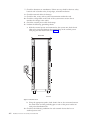
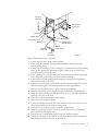
2. Disconnect all power cables.
3. Make sure that the rack is either bolted down or has the stabilizers installed
before continuing this procedure.
4. Before removing any drawers from the rack, ensure that the battery LEDs on
the controller units are NOT blinking. A blinking LED indicates that the
batteries are in use. To ensure that the batteries do not discharge during the
relocation process, remove and reseat the battery packs before removing the
drawer.
Complete the following steps to relocate the rack:
1. Unbolt the rack from the floor or remove the stabilizers.
2. Raise all the leveling feet.
3. Unlock each caster wheel by loosening the screw on the caster.
4. Move the rack to the new position.
5. Reposition the rack. Go to “Step 1. Positioning the rack” on page 2.
Chapter 3. Removal and Replacement
27
28
Installation and Service Guide, 2101 Model 200
Chapter 4. Parts information and product specifications
This chapter contains detailed drawings, field replaceable unit (FRU) part numbers,
part descriptions and product specification for a 2101 Model 200 rack.
Covers
6
7
1
2
3
5
4
RT000017
Index number
FRU part number
Units per assembly
Description
1
18P2120
1
Front Door
2
31L7547
2
Hinge, front door
3
31L8594
4
Screw, front hinge
4
31L7545
1
Latch, front door
5
31L7540
2
Screw, front door
latch
6
11P0724
1
Rear door (Black)
7
05N6478
2
Side panel (Black)
© Copyright IBM Corp. 2005
29
Earthquake brace
3
2
6
1
4
RT000018
5
Index number
30
FRU part number
Units per assembly
Description
05N4697
1
Earthquake brace kit
1
Reference only
1
Bracket
2
Reference only
2
Hinge
3
Reference only
1
Spacer
4
Reference only
7
Screw
5
Reference only
1
Bolt
6
Reference only
1
Latch plate
Installation and Service Guide, 2101 Model 200
Blank fillers
1
5
4
2
3
7
6
8
RT000019
Index number
FRU part number
Units per assembly
Description
1
97H9754
As needed
1U (black) Filler snap
2
97H9755
As needed
3U (black) Filler snap
18P2265
As needed
1U Bolt in panel kit,
(black)
3
Reference only
1
Panel (1U kit)
4
Reference only
2
M5 X 14 Hex screw
(1U kit)
5
Reference only
2
M5 Nut clip (1U kit)
18P2233
As needed
3U Bolt in panel kit,
(black)
6
Reference only
1
Panel (3U kit)
7
Reference only
4
M5 X 14 Hex screw
(3U kit)
8
Reference only
4
M5 Nut clip (3U kit)
Chapter 4. Parts Information
31
Power distribution unit (PDU)
2
1
3
RT000020
Index number
FRU part number
Units per assembly
Description
1
00P2200
1
Type 6 power
distribution unit (1
phase US)
1
26K4247
1
9188/7188 power
distribution unit 1
2
1624779
4
Nut clip (for Type 6
PDU)
3
74F1823
4
Screw (for Type 6
PDU)
1. The 9188/7188 PDU does not ship with the nut clips, screws, L-shaped brackets, or
bracket mounting screws required to mount the 9188/7188 PDU in the rack. If you are
replacing a failed PDU with a 9188/7188 PDU, you must keep the four screws and four
nut clips that secured the failed PDU to the rack. You must also remove the two L-shaped
brackets and four bracket mounting screws from the failed PDU and replace them on the
replacement 9188/7188 PDU before mounting the replacement 9188/7188 PDU.
The following part numbers describe the mounting hardware for the 9188/7188 PDU.
These part numbers are included for reference only.
v 90P4895 — 9188/7188 PDU L-shaped brackets
v 01N6416 — 9188/7188 PDU screws for mounting the L-shaped bracket to the PDU
v 12J5289 — 9188/7188 PDU screws for securing the PDU to the rack
v 90P4895 — 9188/7188 PDU nut clips (used with 12J5289). The nut clips attach to the
rack.
32
Installation and Service Guide, 2101 Model 200
Stabilizers
Front of
Rack
1
2
Rear of
Rack
RT000021
Index number
FRU part number
Units per assembly
Description
31L8305
1
Stabilizer kit (black)
1
Reference only
2
Bracket
2
Reference only
4
M8 X 25 screw,
button head socket
Chapter 4. Parts Information
33
Leveling feet
1
2
3
RT000023
Index number
FRU part number
Units per assembly
Description
1
Reference only
4
Jam nut
2
Reference only
4
Leveller
3
31L8313
1
Wrench
Power cords
1
2
3
4
5
6
RT000024
Table 1 on page 35 lists the power cord FRUs and country and region information
for the Type 6 PDU.
34
Installation and Service Guide, 2101 Model 200
Table 1. Power cord FRU Index for Type 6 PDU
Index number FRU part
number
Units per
assembly
Country or region
1
1
U.S. Standard, type 12 plug, L6-30P
twist-lock connector, 14-foot cord
11F0113
30A, single-phase
U.S.A., Canada
Anguilla, Antigua, Cape Verde Islands,
Cayman Islands, French Polynesia,
Honduras, Montserrat, St. Kitts and Nevis,
Tortola
1
11F0114
1
U.S., Chicago, type 12 plug, L6-30P
twist-lock connector, 6-foot cord
30A, single-phase
Chicago, Illinois, U.S.A.
1
11F0115
1
AFE, type 12 plug, L6-30P twist-lock
connector, 14-foot cord
30A, single-phase
Argentina, Bahamas, Bangladesh, Barbados,
Bermuda, Bolivia, Chile, Colombia, Costa
Rica, Dominican Republic, Ecuador, El
Salvador, Guatemala, Guyana, Honduras,
China (Hong Kong S.A.R.), India,
Indonesia, Jamaica, Japan, China (Macau
S.A.R.), Malaysia, Mexico, Myanmar,
Netherlands Antilles, Panama, Peoples
Republic of China, Peru, Philippines,
Singapore, Sri Lanka, Suriname, Taiwan,
Thailand, Trinidad, Venezuela
N/A
18P2257
1
Universal W/O Wall Plug Connector
(non-US or CAN)
3
11F0106
1
30A, single-phase, PDL connector
Wilco WP, type PDL plug, 14-foot cord
Australia
3
11F0107
1
30 A, single-phase, PDL connector
Wilco WP, type PDL plug, right angle,
14-foot cord
New Zealand
Chapter 4. Parts Information
35
Table 1. Power cord FRU Index for Type 6 PDU (continued)
Index number FRU part
number
Units per
assembly
Country or region
4
1
32A, single-phase, three-pin connector
31F4466
IEC 309, type 46 connector (2 power +
ground), 14-foot cord
Belgium, Bahrain, Botswana, Brazil, Egypt,
Ethiopia, France, Ghana, Germany, Greece,
Iceland, Iraq, Ireland, Italy, Jordan, Kenya,
Kuwait, Lebanon, Malawi, Nigeria,
Norway, Oman, Qatar, Saudi Arabia, Spain,
Sudan, Tanzania, Uganda, United
Kingdom, United Arab Emirates, Zaire,
Zambia, Zimbabwe
5
18P2269
1
16A, 3-phase, five-pin connector
IEC 309, type 46 connector (3 power +
neutral + ground), 14-foot cord
Switzerland
6
87G6067
1
30A, single-phase
Type KP connector, right angle, 14-foot
cord
Korea
Table 2 lists the power cord FRUs and country and region information for the
9188/7188 PDU.
Table 2. Power cord FRU Index for 9188/7188 PDU
Index number FRU part
number
Units per
assembly
Country or region
1
22R2555
1
Linecord, single-phase, PDU to wall,
14-foot (200-240V/24A, UTG0247, PT#12)
3
22R2558
1
Linecord, single-phase, PDU to wall,
14-foot (200-240V/24A, UTG0247, PT#PDL)
4
22R2553
1
Linecord, single-phase, PDU to wall,
14-foot (200-240V/24A, UTG0247, IEC309
32A P+N+G)
6
22R2559
1
Linecord, single-phase, PDU to wall,
14-foot (200-240V/24A, UTG0247, PT#KP)
2101 Model 200 rack specifications
Height: 1785 mm (70.3 in.)
Depth:
With rear door installed: 1042 mm (41 in.)
With rear and front door installed: 1098 mm (43.3 in.)
Width:
With side panels installed: 650 mm (25.6 in.)
Without side panel installed: 623 mm (24.5 in.)
EIA units: 36 EIA units
36
Installation and Service Guide, 2101 Model 200
Weight:
Base Empty Rack: 244 kg (535 lbs)
Full Rack: 816 kg (1795 lbs)
Chapter 4. Parts Information
37
38
Installation and Service Guide, 2101 Model 200
Hardware warranty
This chapter contains information on IBM product warranties and liability.
Statement of limited warranty
International Business Machines Corporation
Armonk, New York, 10504
The warranties provided by IBM in this Statement of Limited Warranty1 apply only to
Machines you originally purchase for your use, and not for resale, from IBM or your
reseller. The term “Machine” means an IBM machine, its features, conversions, upgrades,
elements, or accessories, or any combination of them.
Unless IBM specifies otherwise, the following warranties apply only in the country
where you acquire the Machine. If you have any questions, contact IBM or your
reseller.
Machine: 2101 Model 200
Warranty Period: One Year *
*Contact your place of purchase for warranty service information.
Production status
Each Machine is manufactured from new parts, or new and used parts. In some
cases, the Machine may not be new and may have been previously installed.
Regardless of the Machine’s production status, IBM’s warranty terms apply.
IBM warranty for machines
IBM warrants that each Machine 1) is free from defects in materials and
workmanship and 2) conforms to IBM’s Official Published Specifications. The
warranty period for a Machine is a specified, fixed period commencing on its Date
of Installation. The date on your receipt is the Date of Installation, unless IBM or
your reseller informs you otherwise.
During the warranty period IBM or your reseller, if authorized by IBM, will
provide warranty service under the type of service designated for the Machine and
will manage and install engineering changes that apply to the Machine.
For IBM or your reseller to provide warranty service for a feature, conversion, or
upgrade, IBM or your reseller may require that the Machine on which it is
installed be 1) for certain Machines, the designated, serial-numbered Machine and
2) at an engineering-change level compatible with the feature, conversion, or
upgrade. Many of these transactions involve the removal of parts and their return
to IBM. You represent that all removed parts are genuine and unaltered. A part
that replaces a removed part will assume the warranty service status of the
replaced part.
If a Machine does not function as warranted during the warranty period, IBM or
your reseller will repair it or replace it with one that is at least functionally
1. Form Z125-4753
© Copyright IBM Corp. 2005
39
equivalent, without charge. The replacement may not be new, but will be in good
working order. If IBM or your reseller is unable to repair or replace the Machine,
you may return it to your place of purchase and your money will be refunded.
If you transfer a Machine to another user, warranty service is available to that user
for the remainder of the warranty period. You should give your proof of purchase
and this Statement to that user. However, for Machines which have a lifetime
warranty, this warranty is not transferable.
Warranty service
To obtain warranty service for the Machine, you should contact your reseller or call
IBM. In the United States, call IBM at 1-800-IBM-SERV (426-7378). In Canada, call
IBM at 1-800-465-6666. You might be required to present proof of purchase.
IBM or your reseller will provide certain types of repair and exchange service,
either at your location or at IBM’s or your reseller’s service center, to restore a
Machine to good working order.
When a type of service involves the exchange of a Machine or part, the item IBM
or your reseller replaces becomes its property and the replacement becomes yours.
You represent that all removed items are genuine and unaltered. The replacement
may not be new, but will be in good working order and at least functionally
equivalent to the item replaced. The replacement assumes the warranty service
status of the replaced item. Before IBM or your reseller exchanges a Machine or
part, you agree to remove all features, parts, options, alterations, and attachments
not under warranty service. You also agree to ensure that the Machine is free of
any legal obligations or restrictions that prevent its exchange.
You agree to:
1. Obtain authorization from the owner to have IBM or your reseller service a
Machine that you do not own; and
2. Where applicable, before service is provided:
a. Follow the problem determination, problem analysis, and service request
procedures that IBM or your reseller provide,
b. Secure all programs, data, and funds contained in a Machine, and
c. Inform IBM or your reseller of changes in a Machine’s location.
IBM is responsible for loss of, or damage to, your Machine while it is 1) in IBM’s
possession or 2) in transit in those cases where IBM is responsible for the
transportation charges.
Extent of warranty
IBM does not warrant uninterrupted or error-free operation of a Machine.
The warranties might be voided by misuse, accident, modification, unsuitable
physical or operating environment, improper maintenance by you, removal or
alteration of Machine or parts identification labels, or failure caused by a product
for which IBM is not responsible.
THESE WARRANTIES REPLACE ALL OTHER WARRANTIES OR CONDITIONS,
EXPRESS OR IMPLIED, INCLUDING, BUT NOT LIMITED TO, THE IMPLIED
WARRANTIES OR CONDITIONS OF MERCHANTABILITY AND FITNESS FOR A
PARTICULAR PURPOSE. THESE WARRANTIES GIVE YOU SPECIFIC LEGAL
RIGHTS AND YOU MAY ALSO HAVE OTHER RIGHTS WHICH VARY FROM
40
Installation and Service Guide, 2101 Model 200
JURISDICTION TO JURISDICTION. SOME JURISDICTIONS DO NOT ALLOW
THE EXCLUSION OR LIMITATION OF EXPRESS OR IMPLIED WARRANTIES,
SO THE ABOVE EXCLUSION OR LIMITATION MAY NOT APPLY TO YOU. IN
THAT EVENT SUCH WARRANTIES ARE LIMITED IN DURATION TO THE
WARRANTY PERIOD. NO WARRANTIES APPLY AFTER THAT PERIOD.
Limitation of liability
Circumstances might arise where, because of a default on IBM’s part or other
liability, you are entitled to recover damages from IBM. In each such instance,
regardless of the basis on which you are entitled to claim damages from IBM
(including fundamental breach, negligence, misrepresentation, or other contract or
tort claim), IBM is liable only for:
1. Damages for bodily injury (including death) and damage to real property and
tangible personal property; and
2. The amount of any other actual direct damages or loss, up to the greater of
U.S. $100,000 or the charges (if recurring, 12 months’ charges apply) for the
Machine that is the subject of the claim.
UNDER NO CIRCUMSTANCES IS IBM LIABLE FOR ANY OF THE FOLLOWING:
1) THIRD-PARTY CLAIMS AGAINST YOU FOR LOSSES OR DAMAGES (OTHER
THAN THOSE UNDER THE FIRST ITEM LISTED ABOVE); 2) LOSS OF, OR
DAMAGE TO, YOUR RECORDS OR DATA; OR 3) SPECIAL, INCIDENTAL, OR
INDIRECT DAMAGES OR FOR ANY ECONOMIC CONSEQUENTIAL DAMAGES
(INCLUDING LOST PROFITS OR SAVINGS), EVEN IF IBM OR YOUR RESELLER
IS INFORMED OF THEIR POSSIBILITY. SOME JURISDICTIONS DO NOT
ALLOW THE EXCLUSION OR LIMITATION OF INCIDENTAL OR
CONSEQUENTIAL DAMAGES, SO THE ABOVE EXCLUSION OR LIMITATION
MAY NOT APPLY TO YOU.
Hardware warranty
41
42
Installation and Service Guide, 2101 Model 200
Notices
This information was developed for products and services offered in the U.S.A.
IBM may not offer the products, services, or features discussed in this document in
other countries. Consult your local IBM representative for information on the
products and services currently available in your area. Any reference to an IBM
product, program, or service is not intended to state or imply that only that IBM
product, program, or service may be used. Any functionally equivalent product,
program, or service that does not infringe any IBM intellectual property right may
be used instead. However, it is the user’s responsibility to evaluate and verify the
operation of any non-IBM product, program, or service.
IBM may have patents or pending patent applications covering subject matter
described in this document. The furnishing of this document does not give you
any license to these patents. You can send license inquiries, in writing, to:
IBM Director of Licensing
IBM Corporation
North Castle Drive
Armonk, NY 10504-1785
U.S.A.
The following paragraph does not apply to the United Kingdom or any other
country where such provisions are inconsistent with local law:
INTERNATIONAL BUSINESS MACHINES CORPORATION PROVIDES THIS
PUBLICATIONS “AS IS” WITHOUT WARRANTY OF ANY KIND, EITHER
EXPRESS OR IMPLIED, INCLUDING, BUT NOT LIMITED TO, THE IMPLIED
WARRANTIES OF NON-INFRINGEMENT, MERCHANTABILITY OR FITNESS
FOR A PARTICULAR PURPOSE. Some states do not allow disclaimer of express or
implied warranties in certain transactions, therefore, this statement may not apply
to you.
This information could include technical inaccuracies or typographical errors.
Changes are periodically made to the information herein; these changes will be
incorporated in new editions of the publications. IBM may make improvements
and/or changes in the product(s) and/or program(s) described in this publication
at any time without notice.
Any references in this information to non-IBM Web sites are provided for
convenience only and do not in any manner serve as an endorsement of those Web
sites. The materials at those Web sites are not part of the materials for this IBM
product and use of those Web sites is at your own risk.
IBM may use or distribute any of the information you supply in any way it
believes appropriate without incurring any obligation to you.
Trademarks
The following terms are trademarks of the International Business Machines
Corporation in the United States, other countries, or both:
© Copyright IBM Corp. 2005
43
IBM
IBMLink
IntelliStation
pSeries
TotalStorage
xSeries
Other company, product, and service names may be trademarks or service marks
of others.
Electronic emission statements
This section gives the electronic emission notices or statements for the United
States and other countries.
Federal Communications Commission (FCC) statement
This equipment has been tested and found to comply with the limits for a class A
digital device, pursuant to Part 15 of the FCC Rules. These limits are designed to
provide reasonable protection against harmful interference when the equipment is
operated in a commercial environment. This equipment generates, uses, and can
radiate radio frequency energy and, if not installed and used in accordance with
the instruction manual, may cause harmful interference to radio communications.
Operation of this equipment in a residential area is likely to cause harmful
interference, in which case the user will be required to correct the interference at
his own expense.
Properly shielded and grounded cables and connectors must be used in order to
meet FCC emission limits. IBM is not responsible for any radio or television
interference caused by using other than recommended cables and connectors or by
unauthorized changes or modifications to this equipment. Unauthorized changes
or modifications could void the user’s authority to operate the equipment.
This device complies with Part 15 of the FCC Rules. Operation is subject to the
following two conditions: (1) this device may not cause harmful interference, and
(2) this device must accept any interference received, including interference that
may cause undesired operation.
Industry Canada compliance statement
Avis de conformite a la reglementation d’Industrie Canada: Cet appareil
numerique de la classe A est conform a la norme NMB-003 du Canada.
European community compliance statement
This product is in conformity with the protection requirements of EC Council
Directive 89/336/EEC on the approximation of the laws of the Member States
relating to electromagnetic compatibility. IBM cannot accept responsibility for any
failure to satisfy the protection requirements resulting from a non-recommended
modification of the product, including the fitting of non-IBM option cards.
This product has been tested and found to comply with the limits for Class A
Information Technology Equipment according to European Standard EN 55022. The
limits for Class A equipment were derived for commercial and industrial
environments to provide reasonable protection against interference with licensed
communication equipment.
44
Installation and Service Guide, 2101 Model 200
Attention: This is a Class A product. In a domestic environment, this product
may cause radio interference in which case the user may be required to take
adequate measures.
Where shielded or special cables (for example, cables fitted with ferrites) are used
in the test to make the product comply with the limits:
Properly shielded and grounded cables and connectors must be used in order to
reduce the potential for causing interference to radio and TV communications and
to other electrical or electronic equipment. Such cables and connectors are available
from IBM authorized dealers. IBM cannot accept responsibility for any interference
caused by using other than recommended cables and connectors.
This product is in conformity with the EU council directive 73/23/EEC on the
approximation of the laws of the Member States relating to electrical equipment
designed for use within certain voltage limits. This conformity is based on
compliance with the following harmonized standard: EN60950.
Germany compliance statement
Zulassungsbescheinigung laut Gesetz ueber die elektromagnetische
Vertraeglichkeit von Geraeten (EMVG) vom 30. August 1995.
Dieses Geraet ist berechtigt, in Uebereinstimmung mit dem deutschen EMVG das
EG-Konformitaetszeichen - CE - zu fuehren.
Der Aussteller der Konformitaetserklaeung ist die IBM Deutschland.
Informationen in Hinsicht EMVG Paragraph 3 Abs. (2) 2:
Das Geraet erfuellt die Schutzanforderungen nach EN 50082-1 und
EN 55022 Klasse A.
EN 55022 Klasse A Geraete beduerfen folgender Hinweise:
Nach dem EMVG:
"Geraete duerfen an Orten, fuer die sie
nicht ausreichend entstoert
sind, nur mit besonderer Genehmigung des Bundesministeriums
fuer Post und Telekommunikation oder des Bundesamtes fuer Post und
Telekommunikation
betrieben werden. Die Genehmigung wird erteilt, wenn keine
elektromagnetischen Stoerungen zu erwarten sind. "(Auszug aus dem
EMVG, Paragraph 3, Abs.4)
Dieses Genehmigungsverfahren ist nach Paragraph 9 EMVG in Verbindung
mit der entsprechenden Kostenverordnung (Amtsblatt 14/93)
kostenpflichtig.
Nach der EN 55022:
"Dies ist eine Einrichtung der Klasse A. Diese Einrichtung kann im
Wohnbereich Funkstoerungen verursachen in diesem Fall kann vom
Betreiber verlangt werden, angemessene Massnahmen durchzufuehren
und dafuer aufzukommen."
Anmerkung:
Um die Einhaltung des EMVG sicherzustellen, sind die Geraete wie in den
Handbuechern angegeben zu installieren und zu betreiben.
Notices
45
Japanese Voluntary Control Council for Interference (VCCI)
class 1 statement
Korean Government Ministry of Communication (MOC)
statement
Please note that this device has been approved for business purposes with regard
to electromagnetic interference. If you find that this is not suitable for your use,
you may exchange it for one with a non-business use.
Taiwan class A compliance statement
RT000027
46
Installation and Service Guide, 2101 Model 200
Glossary
This glossary provides definitions for the
terminology and abbreviations used in this
document.
If you do not find the term you are looking for,
see the IBM Glossary of Computing Terms located at
the following Web site:
www.ibm.com/ibm/terminology
This glossary also includes terms and definitions
from:
v Information Technology Vocabulary by
Subcommittee 1, Joint Technical Committee 1,
of the International Organization for
Standardization and the International
Electrotechnical Commission (ISO/IEC
JTC1/SC1). Definitions are identified by the
symbol (I) after the definition; definitions taken
from draft international standards, committee
drafts, and working papers by ISO/IEC
JTC1/SC1 are identified by the symbol (T) after
the definition, indicating that final agreement
has not yet been reached among the
participating National Bodies of SC1.
v IBM Glossary of Computing Terms. New York:
McGraw-Hill, 1994.
The following cross-reference conventions are
used in this glossary:
See
Refers you to (a) a term that is the
expanded form of an abbreviation or
acronym, or (b) a synonym or more
preferred term.
See also
Refers you to a related term.
Abstract Windowing Toolkit (AWT). A Java graphical
user interface (GUI).
accelerated graphics port (AGP). A bus specification
that gives low-cost 3D graphics cards faster access to
main memory on personal computers than the usual
peripheral component interconnect (PCI) bus. AGP
reduces the overall cost of creating high-end graphics
subsystems by using existing system memory.
access volume. A special logical drive that allows the
host-agent to communicate with the controllers in the
storage subsystem.
© Copyright IBM Corp. 2005
adapter. A printed circuit assembly that transmits user
data input/output (I/O) between the internal bus of
the host system and the external fibre-channel (FC) link
and vice versa. Also called an I/O adapter, host
adapter, or FC adapter.
advanced technology (AT) bus architecture. A bus
standard for IBM compatibles. It extends the XT bus
architecture to 16 bits and also allows for bus
mastering, although only the first 16 MB of main
memory are available for direct access.
agent. A server program that receives virtual
connections from the network manager (the client
program) in a Simple Network Management
Protocol-Transmission Control Protocol/Internet
Protocol (SNMP-TCP/IP) network-managing
environment.
AGP. See accelerated graphics port.
AL_PA. See arbitrated loop physical address.
arbitrated loop. One of three existing fibre-channel
topologies, in which 2 - 126 ports are interconnected
serially in a single loop circuit. Access to the Fibre
Channel-Arbitrated Loop (FC-AL) is controlled by an
arbitration scheme. The FC-AL topology supports all
classes of service and guarantees in-order delivery of
FC frames when the originator and responder are on
the same FC-AL. The default topology for the disk
array is arbitrated loop. An arbitrated loop is
sometimes referred to as a Stealth Mode.
arbitrated loop physical address (AL_PA). An 8-bit
value that is used to uniquely identify an individual
port within a loop. A loop can have one or more
AL_PAs.
array. A collection of fibre-channel or SATA hard
drives that are logically grouped together. All the
drives in the array are assigned the same RAID level.
An array is sometimes referred to as a ″RAID set.″ See
also redundant array of independent disks (RAID), RAID
level.
asynchronous write mode. In remote mirroring, an
option that allows the primary controller to return a
write I/O request completion to the host server before
data has been successfully written by the secondary
controller. See also synchronous write mode, remote
mirroring, Global Copy,Global Mirroring.
AT. See advanced technology (AT) bus architecture.
ATA. See AT-attached.
47
AT-attached. Peripheral devices that are compatible
with the original IBM AT computer standard in which
signals on a 40-pin AT-attached (ATA) ribbon cable
followed the timings and constraints of the Industry
Standard Architecture (ISA) system bus on the IBM PC
AT computer. Equivalent to integrated drive electronics
(IDE).
concurrent download. A method of downloading and
installing firmware that does not require the user to
stop I/O to the controllers during the process.
auto-volume transfer/auto-disk transfer (AVT/ADT).
A function that provides automatic failover in case of
controller failure on a storage subsystem.
CRU. See customer replaceable unit.
AVT/ADT. See auto-volume transfer/auto-disk transfer.
AWT. See Abstract Windowing Toolkit.
basic input/output system (BIOS). The personal
computer code that controls basic hardware operations,
such as interactions with diskette drives, hard disk
drives, and the keyboard.
BIOS. See basic input/output system.
BOOTP. See bootstrap protocol.
bootstrap protocol (BOOTP). In Transmission Control
Protocol/Internet Protocol (TCP/IP) networking, an
alternative protocol by which a diskless machine can
obtain its Internet Protocol (IP) address and such
configuration information as IP addresses of various
servers from a BOOTP server.
CRC. See cyclic redundancy check.
CRT. See cathode ray tube.
customer replaceable unit (CRU). An assembly or
part that a customer can replace in its entirety when
any of its components fail. Contrast with field replaceable
unit (FRU).
cyclic redundancy check (CRC). (1) A redundancy
check in which the check key is generated by a cyclic
algorithm. (2) An error detection technique performed
at both the sending and receiving stations.
dac. See disk array controller.
dar. See disk array router.
DASD. See direct access storage device.
data striping. See striping.
default host group. A logical collection of discovered
host ports, defined host computers, and defined host
groups in the storage-partition topology that fulfill the
following requirements:
bridge. A storage area network (SAN) device that
provides physical and transport conversion, such as
fibre channel to small computer system interface (SCSI)
bridge.
v Are not involved in specific logical drive-to-LUN
mappings
bridge group. A bridge and the collection of devices
connected to it.
device type. Identifier used to place devices in the
physical map, such as the switch, hub, or storage.
broadcast. The simultaneous transmission of data to
more than one destination.
DHCP. See Dynamic Host Configuration Protocol.
cathode ray tube (CRT). A display device in which
controlled electron beams are used to display
alphanumeric or graphical data on an
electroluminescent screen.
client. A computer system or process that requests a
service of another computer system or process that is
typically referred to as a server. Multiple clients can
share access to a common server.
command. A statement used to initiate an action or
start a service. A command consists of the command
name abbreviation, and its parameters and flags if
applicable. A command can be issued by typing it on a
command line or selecting it from a menu.
community string. The name of a community
contained in each Simple Network Management
Protocol (SNMP) message.
48
Installation and Service Guide, 2101 Model 200
v Share access to logical drives with default logical
drive-to-LUN mappings
direct access storage device (DASD). A device in
which access time is effectively independent of the
location of the data. Information is entered and
retrieved without reference to previously accessed data.
(For example, a disk drive is a DASD, in contrast with
a tape drive, which stores data as a linear sequence.)
DASDs include both fixed and removable storage
devices.
direct memory access (DMA). The transfer of data
between memory and an input/output (I/O) device
without processor intervention.
disk array controller (dac). A disk array controller
device that represents the two controllers of an array.
See also disk array router.
disk array router (dar). A disk array router that
represents an entire array, including current and
deferred paths to all logical unit numbers (LUNs)
(hdisks on AIX). See also disk array controller.
DMA. See direct memory access.
domain. The most significant byte in the node port
(N_port) identifier for the fibre-channel (FC) device. It
is not used in the fibre channel-small computer system
interface (FC-SCSI) hardware path ID. It is required to
be the same for all SCSI targets logically connected to
an FC adapter.
DRAM. See dynamic random access memory.
Dynamic Host Configuration Protocol (DHCP). A
protocol defined by the Internet Engineering Task Force
that is used for dynamically assigning Internet Protocol
(IP) addresses to computers in a network.
dynamic random access memory (DRAM). A storage
in which the cells require repetitive application of
control signals to retain stored data.
ECC. See error correction coding.
EEPROM. See electrically erasable programmable
read-only memory.
EISA. See Extended Industry Standard Architecture.
electrically erasable programmable read-only memory
(EEPROM). A type of memory chip which can retain
its contents without consistent electrical power. Unlike
the PROM which can be programmed only once, the
EEPROM can be erased electrically. Because it can only
be reprogrammed a limited number of times before it
wears out, it is appropriate for storing small amounts
of data that are changed infrequently.
electrostatic discharge (ESD). The flow of current that
results when objects that have a static charge come into
close enough proximity to discharge.
environmental service module (ESM) canister. A
component in a storage expansion enclosure that
monitors the environmental condition of the
components in that enclosure. Not all storage
subsystems have ESM canisters.
E_port. See expansion port.
error correction coding (ECC). A method for encoding
data so that transmission errors can be detected and
corrected by examining the data on the receiving end.
Most ECCs are characterized by the maximum number
of errors they can detect and correct.
ESD. See electrostatic discharge.
ESM canister. See environmental service module canister.
EXP. See storage expansion enclosure.
expansion port (E_port). A port that connects the
switches for two fabrics.
Extended Industry Standard Architecture (EISA). A
bus standard for IBM compatibles that extends the
Industry Standard Architecture (ISA) bus architecture to
32 bits and allows more than one central processing
unit (CPU) to share the bus. See also Industry Standard
Architecture.
fabric. A Fibre Channel entity which interconnects and
facilitates logins of N_ports attached to it. The fabric is
responsible for routing frames between source and
destination N_ports using address information in the
frame header. A fabric can be as simple as a
point-to-point channel between two N-ports, or as
complex as a frame-routing switch that provides
multiple and redundant internal pathways within the
fabric between F_ports.
fabric port (F_port). In a fabric, an access point for
connecting a user’s N_port. An F_port facilitates
N_port logins to the fabric from nodes connected to the
fabric. An F_port is addressable by the N_port
connected to it. See also fabric.
FAStT MSJ. See FAStT Management Suite Java.
FAStT Management Suite Java (FAStT MSJ). A
diagnostic and configuration utility that can be used on
Linux, Microsoft Windows, and Novell NetWare host
systems. In Linux, it is also used with the QLRemote
agent to define preferred and non-preferred paths for
logical drives.
FC. See fibre channel.
FC-AL. See arbitrated loop.
feature enable identifier. A unique identifier for the
storage subsystem, which is used in the process of
generating a premium feature key. See also premium
feature key.
fibre channel (FC). A set of standards for a serial
input/output (I/O) bus capable of transferring data
between two ports at up to 100 Mbps, with standards
proposals to go to higher speeds. FC supports
point-to-point, arbitrated loop, and switched topologies.
Fibre Channel-Arbitrated Loop (FC-AL). See arbitrated
loop.
Fibre Channel Protocol (FCP) for small computer
system interface (SCSI). A high-level fibre-channel
mapping layer (FC-4) that uses lower-level
fibre-channel (FC-PH) services to transmit SCSI
commands, data, and status information between a
SCSI initiator and a SCSI target across the FC link by
using FC frame and sequence formats.
field replaceable unit (FRU). An assembly that is
replaced in its entirety when any one of its components
fails. In some cases, a field replaceable unit might
contain other field replaceable units. Contrast with
customer replaceable unit (CRU).
Glossary
49
FlashCopy. A premium feature for DS4000 that can
make an instantaneous copy of the data in a volume.
host bus adapter (HBA). An interface between the
fibre-channel network and a workstation or server.
F_port. See fabric port.
host computer. See host.
FRU. See field replaceable unit.
GBIC. See gigabit interface converter
host group. An entity in the storage partition topology
that defines a logical collection of host computers that
require shared access to one or more logical drives.
gigabit interface converter (GBIC). A transceiver that
performs serial, optical-to-electrical, and
electrical-to-optical signal conversions for high-speed
networking. A GBIC can be hot swapped. See also small
form-factor pluggable.
host port. Ports that physically reside on the host
adapters and are automatically discovered by the
DS4000 Storage Manager software. To give a host
computer access to a partition, its associated host ports
must be defined.
Global Copy. Refers to a remote logical drive mirror
pair that is set up using asynchronous write mode
without the write consistency group option. This is also
referred to as ″Asynchronous Mirroring without
Consistency Group.″ Global Copy does not ensure that
write requests to multiple primary logical drives are
carried out in the same order on the secondary logical
drives as they are on the primary logical drives. If it is
critical that writes to the primary logical drives are
carried out in the same order in the appropriate
secondary logical drives, Global Mirroring should be
used instead of Global Copy. See also asynchronous write
mode, Global Mirroring, remote mirroring, Metro Mirroring.
hot swap. To replace a hardware component without
turning off the system.
Global Mirroring. Refers to a remote logical drive
mirror pair that is set up using asynchronous write
mode with the write consistency group option. This is
also referred to as ″Asynchronous Mirroring with
Consistency Group.″ Global Mirroring ensures that
write requests to multiple primary logical drives are
carried out in the same order on the secondary logical
drives as they are on the primary logical drives,
preventing data on the secondary logical drives from
becoming inconsistent with the data on the primary
logical drives. See also asynchronous write mode, Global
Copy, remote mirroring, Metro Mirroring.
IDE. See integrated drive electronics.
graphical user interface (GUI). A type of computer
interface that presents a visual metaphor of a
real-world scene, often of a desktop, by combining
high-resolution graphics, pointing devices, menu bars
and other menus, overlapping windows, icons, and the
object-action relationship.
initial program load (IPL). The initialization
procedure that causes an operating system to
commence operation. Also referred to as a system
restart, system startup, and boot.
GUI. See graphical user interface.
HBA. See host bus adapter.
hdisk. An AIX term representing a logical unit
number (LUN) on an array.
host. A system that is directly attached to the storage
subsystem through a fibre-channel input/output (I/O)
path. This system is used to serve data (typically in the
form of files) from the storage subsystem. A system can
be both a storage management station and a host
simultaneously.
50
Installation and Service Guide, 2101 Model 200
hub. In a network, a point at which circuits are either
connected or switched. For example, in a star network,
the hub is the central node; in a star/ring network, it is
the location of wiring concentrators.
IBMSAN driver. The device driver that is used in a
Novell NetWare environment to provide multipath
input/output (I/O) support to the storage controller.
IC. See integrated circuit.
in-band. Transmission of management protocol over
the fibre-channel transport.
Industry Standard Architecture (ISA). Unofficial
name for the bus architecture of the IBM PC/XT
personal computer. This bus design included expansion
slots for plugging in various adapter boards. Early
versions had an 8-bit data path, later expanded to 16
bits. The ″Extended Industry Standard Architecture″
(EISA) further expanded the data path to 32 bits. See
also Extended Industry Standard Architecture.
integrated circuit (IC). A microelectronic
semiconductor device that consists of many
interconnected transistors and other components. ICs
are constructed on a small rectangle cut from a silicon
crystal or other semiconductor material. The small size
of these circuits allows high speed, low power
dissipation, and reduced manufacturing cost compared
with board-level integration. Also known as a chip.
integrated drive electronics (IDE). A disk drive
interface based on the 16-bit IBM personal computer
Industry Standard Architecture (ISA) in which the
controller electronics reside on the drive itself,
eliminating the need for a separate adapter card. Also
known as an Advanced Technology Attachment
Interface (ATA).
a single physical partition. (3) One to three physical
partitions (copies). The number of logical partitions
within a logical volume is variable.
Internet Protocol (IP). A protocol that routes data
through a network or interconnected networks. IP acts
as an intermediary between the higher protocol layers
and the physical network.
logical unit number (LUN). An identifier used on a
small computer system interface (SCSI) bus to
distinguish among up to eight devices (logical units)
with the same SCSI ID.
Internet Protocol (IP) address. The unique 32-bit
address that specifies the location of each device or
workstation on the Internet. For example, 9.67.97.103 is
an IP address.
loop address. The unique ID of a node in
fibre-channel loop topology sometimes referred to as a
loop ID.
interrupt request (IRQ). A type of input found on
many processors that causes the processor to suspend
normal processing temporarily and start running an
interrupt handler routine. Some processors have several
interrupt request inputs that allow different priority
interrupts.
loop group. A collection of storage area network
(SAN) devices that are interconnected serially in a
single loop circuit.
loop port. A node port (N_port) or fabric port (F_port)
that supports arbitrated loop functions associated with
an arbitrated loop topology.
IP. See Internet Protocol.
LPAR. See logical partition.
IPL. See initial program load.
LUN. See logical unit number.
IRQ. See interrupt request.
MAC. See medium access control.
ISA. See Industry Standard Architecture.
management information base (MIB). The
information that is on an agent. It is an abstraction of
configuration and status information.
Java Runtime Environment (JRE). A subset of the
Java Development Kit (JDK) for end users and
developers who want to redistribute the Java Runtime
Environment (JRE). The JRE consists of the Java virtual
machine, the Java Core Classes, and supporting files.
JRE. See Java Runtime Environment.
label. A discovered or user entered property value
that is displayed underneath each device in the
Physical and Data Path maps.
LAN. See local area network.
LBA. See logical block address.
local area network (LAN). A computer network
located on a user’s premises within a limited
geographic area.
logical block address (LBA). The address of a logical
block. Logical block addresses are typically used in
hosts’ I/O commands. The SCSI disk command
protocol, for example, uses logical block addresses.
logical partition (LPAR). (1) A subset of a single
system that contains resources (processors, memory,
and input/output devices). A logical partition operates
as an independent system. If hardware requirements
are met, multiple logical partitions can exist within a
system. (2) A fixed-size portion of a logical volume. A
logical partition is the same size as the physical
partitions in its volume group. Unless the logical
volume of which it is a part is mirrored, each logical
partition corresponds to, and its contents are stored on,
man pages. In UNIX-based operating systems, online
documentation for operating system commands,
subroutines, system calls, file formats, special files,
stand-alone utilities, and miscellaneous facilities.
Invoked by the man command.
MCA. See micro channel architecture.
media scan. A media scan is a background process
that runs on all logical drives in the storage subsystem
for which it has been enabled, providing error detection
on the drive media. The media scan process scans all
logical drive data to verify that it can be accessed, and
optionally scans the logical drive data also.
medium access control (MAC). In local area networks
(LANs), the sublayer of the data link control layer that
supports medium-dependent functions and uses the
services of the physical layer to provide services to the
logical link control sublayer. The MAC sublayer
includes the method of determining when a device has
access to the transmission medium.
Metro Mirroring. This term is used to refer to a
remote logical drive mirror pair which is set up with
synchronous write mode. See also remote mirroring,
Global Mirroring.
MIB. See management information base.
micro channel architecture (MCA). Hardware that is
used for PS/2 Model 50 computers and above to
Glossary
51
provide better growth potential and performance
characteristics when compared with the original
personal computer design.
N_port. See node port.
Microsoft Cluster Server (MSCS). MSCS, a feature of
Windows NT Server (Enterprise Edition), supports the
connection of two servers into a cluster for higher
availability and easier manageability. MSCS can
automatically detect and recover from server or
application failures. It can also be used to balance
server workload and provide for planned maintenance.
NVSRAM. Nonvolatile storage random access
memory. See nonvolatile storage.
mini hub. An interface card or port device that
receives short-wave fiber channel GBICs or SFPs. These
devices enable redundant fibre channel connections
from the host computers, either directly or through a
fibre channel switch or managed hub, over optical fiber
cables to the DS4000 Storage Server controllers. Each
DS4000 controller is responsible for two mini hubs.
Each mini hub has two ports. Four host ports (two on
each controller) provide a cluster solution without use
of a switch. Two host-side mini hubs are shipped as
standard. See also host port, gigabit interface converter
(GBIC), small form-factor pluggable (SFP).
mirroring. A fault-tolerance technique in which
information on a hard disk is duplicated on additional
hard disks. See also remote mirroring.
model. The model identification that is assigned to a
device by its manufacturer.
MSCS. See Microsoft Cluster Server.
network management station (NMS). In the Simple
Network Management Protocol (SNMP), a station that
runs management application programs that monitor
and control network elements.
NMI. See non-maskable interrupt.
NMS. See network management station.
non-maskable interrupt (NMI). A hardware interrupt
that another service request cannot overrule (mask). An
NMI bypasses and takes priority over interrupt
requests generated by software, the keyboard, and
other such devices and is issued to the microprocessor
only in disastrous circumstances, such as severe
memory errors or impending power failures.
node. A physical device that allows for the
transmission of data within a network.
node port (N_port). A fibre-channel defined hardware
entity that performs data communications over the
fibre-channel link. It is identifiable by a unique
worldwide name. It can act as an originator or a
responder.
nonvolatile storage (NVS). A storage device whose
contents are not lost when power is cut off.
52
Installation and Service Guide, 2101 Model 200
NVS. See nonvolatile storage.
Object Data Manager (ODM). An AIX proprietary
storage mechanism for ASCII stanza files that are
edited as part of configuring a drive into the kernel.
ODM. See Object Data Manager.
out-of-band. Transmission of management protocols
outside of the fibre-channel network, typically over
Ethernet.
partitioning. See storage partition.
parity check. (1) A test to determine whether the
number of ones (or zeros) in an array of binary digits is
odd or even. (2) A mathematical operation on the
numerical representation of the information
communicated between two pieces. For example, if
parity is odd, any character represented by an even
number has a bit added to it, making it odd, and an
information receiver checks that each unit of
information has an odd value.
PCI local bus. See peripheral component interconnect
local bus.
PDF. See portable document format.
performance events. Events related to thresholds set
on storage area network (SAN) performance.
peripheral component interconnect local bus (PCI
local bus). A local bus for PCs, from Intel, that
provides a high-speed data path between the CPU and
up to 10 peripherals (video, disk, network, and so on).
The PCI bus coexists in the PC with the Industry
Standard Architecture (ISA) or Extended Industry
Standard Architecture (EISA) bus. ISA and EISA boards
plug into an IA or EISA slot, while high-speed PCI
controllers plug into a PCI slot. See also Industry
Standard Architecture, Extended Industry Standard
Architecture.
polling delay. The time in seconds between successive
discovery processes during which discovery is inactive.
port. A part of the system unit or remote controller to
which cables for external devices (such as display
stations, terminals, printers, switches, or external
storage units) are attached. The port is an access point
for data entry or exit. A device can contain one or more
ports.
portable document format (PDF). A standard
specified by Adobe Systems, Incorporated, for the
electronic distribution of documents. PDF files are
compact; can be distributed globally by e-mail, the
Web, intranets, or CD-ROM; and can be viewed with
the Acrobat Reader, which is software from Adobe
Systems that can be downloaded at no cost from the
Adobe Systems home page.
premium feature key. A file that the storage
subsystem controller uses to enable an authorized
premium feature. The file contains the feature enable
identifier of the storage subsystem for which the
premium feature is authorized, and data about the
premium feature. See also feature enable identifier.
private loop. A freestanding arbitrated loop with no
fabric attachment. See also arbitrated loop.
separate media. The Enhanced Remote Mirror Option is
a DS4000 premium feature that provides support for
remote mirroring. See also Global Mirroring, Metro
Mirroring.
ROM. See read-only memory.
router. A computer that determines the path of
network traffic flow. The path selection is made from
several paths based on information obtained from
specific protocols, algorithms that attempt to identify
the shortest or best path, and other criteria such as
metrics or protocol-specific destination addresses.
program temporary fix (PTF). A temporary solution
or bypass of a problem diagnosed by IBM in a current
unaltered release of the program.
RVSD. See recoverable virtual shared disk.
PTF. See program temporary fix.
SA Identifier. See Storage Array Identifier.
RAID. See redundant array of independent disks (RAID).
SAN. See storage area network.
RAID level. An array’s RAID level is a number that
refers to the method used to achieve redundancy and
fault tolerance in the array. See also array, redundant
array of independent disks (RAID).
SATA. See serial ATA.
SAI. See Storage Array Identifier.
RAID set. See array.
scope. Defines a group of controllers by their Internet
Protocol (IP) addresses. A scope must be created and
defined so that dynamic IP addresses can be assigned
to controllers on the network.
RAM. See random-access memory.
SCSI. See small computer system interface.
random-access memory (RAM). A temporary storage
location in which the central processing unit (CPU)
stores and executes its processes. Contrast with DASD.
segmented loop port (SL_port). A port that allows
division of a fibre-channel private loop into multiple
segments. Each segment can pass frames around as an
independent loop and can connect through the fabric to
other segments of the same loop.
RDAC. See redundant disk array controller.
read-only memory (ROM). Memory in which stored
data cannot be changed by the user except under
special conditions.
recoverable virtual shared disk (RVSD). A virtual
shared disk on a server node configured to provide
continuous access to data and file systems in a cluster.
redundant array of independent disks (RAID). A
collection of disk drives (array) that appears as a single
volume to the server, which is fault tolerant through an
assigned method of data striping, mirroring, or parity
checking. Each array is assigned a RAID level, which is
a specific number that refers to the method used to
achieve redundancy and fault tolerance. See also array,
parity check, mirroring, RAID level, striping.
sense data. (1) Data sent with a negative response,
indicating the reason for the response. (2) Data
describing an I/O error. Sense data is presented to a
host system in response to a sense request command.
serial ATA. The standard for a high-speed alternative
to small computer system interface (SCSI) hard drives.
The SATA-1 standard is equivalent in performance to a
10 000 RPM SCSI drive.
serial storage architecture (SSA). An interface
specification from IBM in which devices are arranged
in a ring topology. SSA, which is compatible with small
computer system interface (SCSI) devices, allows
full-duplex packet multiplexed serial data transfers at
rates of 20 Mbps in each direction.
redundant disk array controller (RDAC). (1) In
hardware, a redundant set of controllers (either
active/passive or active/active). (2) In software, a layer
that manages the input/output (I/O) through the
active controller during normal operation and
transparently reroutes I/Os to the other controller in
the redundant set if a controller or I/O path fails.
server. A functional hardware and software unit that
delivers shared resources to workstation client units on
a computer network.
remote mirroring. Online, real-time replication of data
between storage subsystems that are maintained on
SFP. See small form-factor pluggable.
server/device events. Events that occur on the server
or a designated device that meet criteria that the user
sets.
Glossary
53
Simple Network Management Protocol (SNMP). In
the Internet suite of protocols, a network management
protocol that is used to monitor routers and attached
networks. SNMP is an application layer protocol.
Information on devices managed is defined and stored
in the application’s Management Information Base
(MIB).
SL_port. See segmented loop port.
SMagent. The DS4000 Storage Manager optional
Java-based host-agent software, which can be used on
Microsoft Windows, Novell NetWare, HP-UX, and
Solaris host systems to manage storage subsystems
through the host fibre-channel connection.
SMclient. The DS4000 Storage Manager client
software, which is a Java-based graphical user interface
(GUI) that is used to configure, manage, and
troubleshoot storage servers and storage expansion
enclosures in a DS4000 storage subsystem. SMclient can
be used on a host system or on a storage management
station.
SMruntime. A Java compiler for the SMclient.
SMutil. The DS4000 Storage Manager utility software
that is used on Microsoft Windows, HP-UX, and Solaris
host systems to register and map new logical drives to
the operating system. In Microsoft Windows, it also
contains a utility to flush the cached data of the
operating system for a particular drive before creating a
FlashCopy.
small computer system interface (SCSI). A standard
hardware interface that enables a variety of peripheral
devices to communicate with one another.
small form-factor pluggable (SFP). An optical
transceiver that is used to convert signals between
optical fiber cables and switches. An SFP is smaller
than a gigabit interface converter (GBIC). See also
gigabit interface converter.
SNMP. See Simple Network Management Protocol and
SNMPv1.
SNMP trap event. (1) (2) An event notification sent by
the SNMP agent that identifies conditions, such as
thresholds, that exceed a predetermined value. See also
Simple Network Management Protocol.
SNMPv1. The original standard for SNMP is now
referred to as SNMPv1, as opposed to SNMPv2, a
revision of SNMP. See also Simple Network Management
Protocol.
SRAM. See static random access memory.
SSA. See serial storage architecture.
static random access memory (SRAM). Random
access memory based on the logic circuit know as
54
Installation and Service Guide, 2101 Model 200
flip-flop. It is called static because it retains a value as
long as power is supplied, unlike dynamic random
access memory (DRAM), which must be regularly
refreshed. It is however, still volatile, meaning that it
can lose its contents when the power is turned off.
storage area network (SAN). A dedicated storage
network tailored to a specific environment, combining
servers, storage products, networking products,
software, and services. See also fabric.
Storage Array Identifier (SAI or SA Identifier). The
Storage Array Identifier is the identification value used
by the DS4000 Storage Manager host software
(SMClient) to uniquely identify each managed storage
server. The DS4000 Storage Manager SMClient program
maintains Storage Array Identifier records of
previously-discovered storage servers in the host
resident file, which allows it to retain discovery
information in a persistent fashion.
storage expansion enclosure (EXP). A feature that can
be connected to a system unit to provide additional
storage and processing capacity.
storage management station. A system that is used to
manage the storage subsystem. A storage management
station does not need to be attached to the storage
subsystem through the fibre-channel input/output
(I/O) path.
storage partition. Storage subsystem logical drives
that are visible to a host computer or are shared among
host computers that are part of a host group.
storage partition topology. In the DS4000 Storage
Manager client, the Topology view of the Mappings
window displays the default host group, the defined
host group, the host computer, and host-port nodes.
The host port, host computer, and host group
topological elements must be defined to grant access to
host computers and host groups using logical
drive-to-LUN mappings.
striping. Splitting data to be written into equal blocks
and writing blocks simultaneously to separate disk
drives. Striping maximizes performance to the disks.
Reading the data back is also scheduled in parallel,
with a block being read concurrently from each disk
then reassembled at the host.
subnet. An interconnected but independent segment
of a network that is identified by its Internet Protocol
(IP) address.
sweep method. A method of sending Simple Network
Management Protocol (SNMP) requests for information
to all the devices on a subnet by sending the request to
every device in the network.
switch. A fibre-channel device that provides full
bandwidth per port and high-speed routing of data by
using link-level addressing.
switch group. A switch and the collection of devices
connected to it that are not in other groups.
switch zoning. See zoning.
synchronous write mode. In remote mirroring, an
option that requires the primary controller to wait for
the acknowledgment of a write operation from the
secondary controller before returning a write I/O
request completion to the host. See also asynchronous
write mode, remote mirroring, Metro Mirroring.
system name. Device name assigned by the vendor’s
third-party software.
Presumably, the actual recipient is a software
application running at the IP address and listening to
the port.
TSR program. See terminate and stay resident program.
uninterruptible power supply. A source of power
from a battery that is installed between a computer
system and its power source. The uninterruptible
power supply keeps the system running if a
commercial power failure occurs, until an orderly
shutdown of the system can be performed.
TCP. See Transmission Control Protocol.
user action events. Actions that the user takes, such as
changes in the storage area network (SAN), changed
settings, and so on.
TCP/IP. See Transmission Control Protocol/Internet
Protocol.
worldwide port name (WWPN). A unique identifier
for a switch on local and global networks.
terminate and stay resident program (TSR program).
A program that installs part of itself as an extension of
DOS when it is executed.
worldwide name (WWN). A globally unique 64-bit
identifier assigned to each Fibre Channel port.
topology. The physical or logical arrangement of
devices on a network. The three fibre-channel
topologies are fabric, arbitrated loop, and
point-to-point. The default topology for the disk array
is arbitrated loop.
WORM. See write-once read-many.
write-once read many (WORM). Any type of storage
medium to which data can be written only a single
time, but can be read from any number of times. After
the data is recorded, it cannot be altered.
TL_port. See translated loop port.
WWN. See worldwide name.
transceiver. A device that is used to transmit and
receive data. Transceiver is an abbreviation of
transmitter-receiver.
zoning. (1) In Fibre Channel environments, the
grouping of multiple ports to form a virtual, private,
storage network. Ports that are members of a zone can
communicate with each other, but are isolated from
ports in other zones. (2) A function that allows
segmentation of nodes by address, name, or physical
port and is provided by fabric switches or hubs.
translated loop port (TL_port). A port that connects to
a private loop and allows connectivity between the
private loop devices and off loop devices (devices not
connected to that particular TL_port).
Transmission Control Protocol (TCP). A
communication protocol used in the Internet and in
any network that follows the Internet Engineering Task
Force (IETF) standards for internetwork protocol. TCP
provides a reliable host-to-host protocol between hosts
in packed-switched communication networks and in
interconnected systems of such networks. It uses the
Internet Protocol (IP) as the underlying protocol.
Transmission Control Protocol/Internet Protocol
(TCP/IP). A set of communication protocols that
provide peer-to-peer connectivity functions for both
local and wide-area networks.
trap. In the Simple Network Management Protocol
(SNMP), a message sent by a managed node (agent
function) to a management station to report an
exception condition.
trap recipient. Receiver of a forwarded Simple
Network Management Protocol (SNMP) trap.
Specifically, a trap receiver is defined by an Internet
Protocol (IP) address and port to which traps are sent.
Glossary
55
56
Installation and Service Guide, 2101 Model 200
Index
A
about this book xi
ac power cords, external 19, 34
ac power distribution unit 13
9188/7188 16
MAP 20
power-off procedure 24
power-on procedure 23
removal 24
replacement 25
testing 20
Type 6 13
attachment
of front door 9
of mounting plate 9
of stabilizers 3
to concrete floor 4, 6
audience xi
external ac power cords 19, 34
M
F
maintenance analysis procedures
(MAP) 20
MAP 20
mounting plate attachment 9
FCC
emission limits 44
rules 44
statement 44
Federal Communications Commission
(FCC) statement 44
fire suppression xiii
front door attachment 9
G
Germany compliance statement
glossary 47
hardware service and support
hardware warranty 39
high voltage (ac) 19
battery return ix
blank fillers 31
book, about this xi
brace, earthquake 30
optical ports, restrictions ix
P
xii
I
C
checking power source 10
comments, how to send xiii
compliance statement
European community 44
Germany 45
concrete floor rack attachment 4, 6
connection
of drawer and device cables 11
cords, power 19, 34
covers 29
IBM, warranty for machines 39
Industry Canada compliance
statement 44
information, parts 29
inspection, safety vii
installation procedures 1
interference, radios and televisions
44
J
Japanese Voluntary Control Council for
Interference (VCCI) class 1
statement 46
D
device cable connection 11
disposal ix
distribution of power 13
door, removal and replacement
drawer connection 11
dust plugs ix
E
earthquake brace 30
edition notice ii
electrical safety 23
electronic emission
statement 44
environmental
notices ix
statements ix
extent of warranty 40
© Copyright IBM Corp. 2005
K
25
notices 43
environmental vii
safety vii, 1, 3, 20, 23
safety translation vii
O
45
H
B
N
Korean Government Ministry of
Communication (MOC) statement
46
L
laser safety ix
LED 20, 27
leveling feet 34
leveling the rack 3
liability, limit of 41
light emitting diode (LED) 20, 27
limitation of liability 41
limited warranty statement (SOLW)
parts
blank fillers 31
covers 29
earthquake brace 30
leveling feet 34
power cords 34
power distribution unit (PDU) 32
stabilizers 33
parts information 29
position of the rack 2
power
distribution of 13
power cords
external 19, 34
power distribution unit (PDU) 13
9188/7188 16
parts 32
power-off procedure 24
power-on procedure 23
removing 24
replacing 25
testing 20
Type 6 13
power source check 10
power-off procedure 24
power-on procedure 11, 23
product specifications 29, 36
production status 39
R
39
rack
leveling 3
position 2
power-off procedure 24
power-on procedure 23
relocation 26
removal and replacement
service 23
radio interference 44
24
57
range of operating temperatures ix
recycling ix
relocation of racks 26
removal and replacement
of the doors 25
of the PDU 24
restrictions
maximum number of drawers per pair
of PDUs 11, 14, 16
of the machine ix
of the optical ports ix
power cord 11, 14, 16
usage ix
warranty (continued)
service
IBM machines 40
phone number 40
statement, limited 39
web sites, related xii
who should use this book
S
safety
electrical 23
inspection procedure vii
laser vii, ix
notice translations vii
notices vii, 1, 3, 10, 11, 20, 23
service, warranty 40
servicing the rack 23
software service and support xii
SOLW (limited warranty statement) 39
specifications, product 36
stabilizer attachment 3
stabilizers 33
statement
electronic emission 44
European community compliance 44
Federal Communications
Commission 44
German only compliance
statement 45
Industry Canada compliance 44
Japanese Voluntary Control Council
for Interference (VCCI) class 1 46
Korean Government Ministry of
Communication (MOC) 46
of limited warranty 39
Taiwan class A compliance 46
status, production 39
system power on 11
T
Taiwan class A compliance statement
temperature range, operating ix
testing procedure, PDU 20
trademarks 43
46
U
unauthorized changes or
modifications 44
W
warranty
extent of 40
for IBM machines
hardware 39
limited 39
58
39
Installation and Service Guide, 2101 Model 200
xi
Readers’ comments—we would like to hear from you
IBM Storage Solution Rack
2101 Model 200
Installation and Service Guide
Publication No. SY27-7622-01
Overall, how satisfied are you with the information in this book?
Overall satisfaction
Very Satisfied
Satisfied
Neutral
Dissatisfied
h
h
h
h
Very
Dissatisfied
h
How satisfied are you that the information in this book is:
Accurate
Complete
Easy to find
Easy to understand
Well organized
Applicable to your tasks
Very Satisfied
Satisfied
Neutral
Dissatisfied
h
h
h
h
h
h
h
h
h
h
h
h
h
h
h
h
h
h
h
h
h
h
h
h
Very
Dissatisfied
h
h
h
h
h
h
Please tell us how we can improve this book:
Thank you for your responses. May we contact you?
h Yes
h No
When you send comments to IBM, you grant IBM a nonexclusive right to use or distribute your comments in any
way it believes appropriate without incurring any obligation to you.
Name
Company or Organization
Phone No.
Address
SY27-7622-01
___________________________________________________________________________________________________
Readers’ Comments — We’d Like to Hear from You
Cut or Fold
Along Line
_ _ _ _ _ _ _Fold
_ _ _and
_ _ _Tape
_ _ _ _ _ _ _ _ _ _ _ _ _ _ _ _ _ _ _ _ _ _ _ _ _ _ _Please
_ _ _ _ _do
_ _not
_ _ staple
_ _ _ _ _ _ _ _ _ _ _ _ _ _ _ _ _ _ _ _ _ _ _ _ _ _ _ _ _Fold
_ _ _and
_ _ Tape
______
NO POSTAGE
NECESSARY
IF MAILED IN THE
UNITED STATES
BUSINESS REPLY MAIL
FIRST-CLASS MAIL
PERMIT NO. 40
ARMONK, NEW YORK
POSTAGE WILL BE PAID BY ADDRESSEE
International Business Machines Corporation
RCF Processing Department
G26/050
5600 Cottle Road
San Jose, CA 95193-0001
_________________________________________________________________________________________
Please do not staple
Fold and Tape
Fold and Tape
SY27-7622-01
Cut or Fold
Along Line
Part Number: 22R4077
SY27-7622-01
(1P) P/N: 22R4077
Printed in USA
Spine information:
IBM Storage Solution Rack
Installation and Service Guide, 2101 Model 200