1
,®
INCLINE
TRAINER
Patent Pending
Model No. NTK14940
Seda! No.
'S
Find the seriaUnumber in the Uocation
shown beUow,Write the seriaUnumber
in the space above for reference,
SeriaUNumber
if you have questions, or if there
are missing parts, we wilt guarantee complete satisfaction
through direct assistance from
our factory.
TO AVOID DELAYS, PLEASE
CALL DIRECT TO OUR TOLLFREE CUSTOMER HOT LINE.
The trained technicians on our
Customer Rot Line will provide
immediate assistance, free of
charge to you.
CUSTOMER HOT LINE:
1o888-825-2588
Mon.=Fd.,
6 a.m.=6 p.m. MST
Read all precautions and instrueo
tions in this manual before usi ng
this equipment. Save this manual
for future reference.
www.nordictrack.com
new products, prizes,
fitness tips, and much more!
lt_lCLi
NE
TRAINER
TABLE OF CONTENTS
iMPORTANT PRECAUTIONS .................................................................
BEFORE YOU BEGIN .......................................................................
ASSEMBLY ...............................................................................
OPERATION AND ADJUSTMENT
............................................................
HOW TO FOLD AND MOVE THE iNCLiNE TRAINER .............................................
TROUBLESHOOTING
......................................................................
CONDiTiONiNG GUiDELiNES ...............................................................
PART LiST ...............................................................................
ORDERING REPLACEMENT PARTS ..........................................................
LiMiTED WARRANTY ...............................................................
Note: An EXPLODED DRAWING is attached in the center of this manual,
NordicTrack is a registered trademark of iCON IP, Inc,
2
3
5
6
11
28
30
33
34
35
Back Cover
iMPORTANT PRECAUTIONS
WARN raNG:Toreduce
theriskofburns,
fire,01eetric
shock,
orinjury
topersons,
read
the
following
important precautions
a nd information
before operating
it is the responsibility
of the owner to ensure
that alJ users of this incline trainer are adequately informed
tions.
2.
12. Failure to use a property functioning surge
suppressor couJd reauJt in damage to the controJ system of the incline trainer, ff the control
system is damaged, the walking beJt may
change speed, accelerate, or stop unexpectedly, which may resuJt in a falJ and serious injury.
of all wami ngs and precau-
Use the incline trainer only as described.
3. Place the incline trainer on a level surface,
with at least eight feet of clearance behind it
and two feet on each side. Do not place the
incline trainer on any surface that blocks air
openings. To protect the floor or carpet from
damage, place a mat under the incline trainer.
=
13. Keep the power cord and the surge suppressor away from heated surfaces.
14. Never move the walking belt while the power
is turned off. Do not operate the incline
trainer if the power cord or plug is damaged,
Dr if the incline trainer Is not working prop=
eHy. (See BEFORE YOU BEGIN on page 5 if
the incline trainer is not working properly.)
Keep the incline trainer indoors, away from
moisture and dust. Do not put the incline
trainer in a garage or covered patio, or near
water.
15. Never start the incline trainer while you are
standing on the waJking beJt. Always hold the
handrails while using the incline trainer.
5. Do not operate the incJine trainer where
aerosol products are used or where oxygen is
being administered.
16. The incline trainer is capable of high speeds.
Adjust the speed in smalt increments to avoid
sudden jumps in speed.
8. Keep children under the age of 12 and pets
away from the ineJine trainer at aH times,
7. The incline trainer should not be used by per=
sons weighing more than 300 pounds.
17. The pulse sensor is not a medical device.
Various factors, including the user's movement, may affect the accuracy of heart rate
readings. The puJae sensor is intended onl y
as an exercise aid in determining
heart rate
trends in general
8. Never alJow more than one person on the incline trainer at a time.
9=
Wear appropriate exercise clothes when
using the incline trainer. Do not wear loose
cloi bee that could become caught in the ino
cHne trainer. AtHetic support clothes are recommended for both men and women. Always
wear athletic shoes. Never use the incline
18. Never leave the incJine trainer unattended
while it is runn ing. Always remove the key, unplug the power cord, and switch the reset/off
circuit breaker to the off position when the in=
cHne trainer is not in use. (See the drawing on
page 5 for the location of the reset/off circuit
breaker.)
trainer with bare feet, wearing only stockings,
or in sandals.
10. When connecting the power cord (see page 11),
pl ug the power cord into a surge suppressor
(not included) and pJug the surge suppressor
into a grounded circuit capable of carrying 15
or more ampe. No other appliance should be on
the same circuit. Do not use an extension cord.
11. Use only a single-outJet surge suppressor that
meets aH of the specifications
described on
page 11. To purchase a surge suppressor, see
your local NordicTrack dea_er or call 1-888825=2588 and order part number 146148.
the incline trainer.
1g. Do not attempt to raise, lower, or move the incJine trainer until it is properly aseembJed.
(See ASSEMBLY on page 6, and HOW TO
FOLD AND MOVE THE iNCLINE TRAINER on
page 28.) You must be able to eafeJy lift 45
poLunds (20 kg) to raise, tower, or move the incJine trainer.
20. Do not change the incline of the incline
trainer by placing objects under the incline
trainer.
3
21. Use the upper body handles only at walking
speeds. Using the handles and not holding
the handrails may compromise your ability to
maintain your balance. Exercises using the
handles shoutd be attempted only by experi=
enced users,
25. Always remove iFmT.com CDs and videos from
your CD player or VCR when you are not
using them.
22. When folding or moving the incline trainer,
make sure that the storage latch is fully
closed.
27. Never insert or drop any object into any
opening.
23. When using iFIT.com CDs and videos, an
electronic "chirping"
sound wHJ alert you
when the speed and/or incline of the incJine
trainer is about to change. Always listen for
the "chirp" and be prepared for speed and/or
incline changss, mnsome instances, the speed
and/or incline may change before the per°
sonal trainer describes the change.
24. When using iFiT.com CDs and videos, you
can manually override the speed and incline
settings by pressing the speed and incline
buttons. However, when the next "chirp" is
heard, the speed and/or incline will change to
the next settings of the CD or video program.
WARNING:
26. inspect and properly tighten all parts of the
incline trainer regularly.
28.DANGER: Always
unpJug
thepower
cord immediately after use, before cleaning
the incline trainer, and before performing the
maintenance and adjustment procedures described in this manual Never remove the
motor hood unless instructed to do so by an
authorized service representative.
Servicing
other than the procedures in this manual
should be performed by an authorized service
representative
only.
29. The incline trainer is intended for in-home use
only. Do not use the incJine trainer in a com_
merciaL rental or institutional setting.
Before
beg .ning
th soranye eroiseprogram,
consult
yourphysician.
This
is especially important for persons over the age of 35 or persons with pre-existing health problems.
Read aH instructions
before using, iCON assumes no responsibility
for personal injury or property
damage sustained by or through the use of this product.
SAVE THESE iNSTRUCTiONS
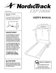
The decals shown here have been placed on your incline trainer, if a decal is missing or
illegible, please call our Customer Service Department, toll=free, to order a free replacement decal (see ORDERING REPLACEMENT PARTS on page 35). Apply the decal in the
[ocation shown. Note: The decals may not be shown at actual size.
PI0tect yourself and
othersfrom dsk ofserious
BEFORE YOU BEGIN
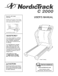
Thank you for selecting the revolutionary NordicTrack _>
X5 incline trainer, The X5 incline trainer offers a selection of features designed to make your workouts at
home more enjoyable and effective, And when you're
not exercising, the unique X5 incline trainer can be
folded up, requiring less floor space,
For your benefit, read this manuaJ carefully before
using the incline trainer, if you have questions after
reading this manual, please call our Customer Service
Department toll-free at 1°888°825°2588, Monday
through Friday, 6 a,m, until 6 p,m, Mountain Time (ex°
cluding holidays), To help us assist you, please note
the product model number and serial number before
calling, The model number of the incline trainer is
NTK14940, The serial number can be found on a decal
attached to the incline trainer (see the front cover of
this manual for the location),
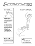
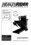
Before reading further, please familiarize yourself with
the parts that are labeled in the drawing below,
Handgrip Pulse Sensor
Handrail
Upper Body Handles
Console
Latch Knob
Fan
Key/Clip
Water Bottle Holder*
Walking Belt
Foot Rail
/
Reset/Off
Circuit Breaker
/
\_
Power Cord
Cushioned Walking Platform
Rear Roller
Adjustment Bolts
*No water bottle is included
AssembJyrequirestwo persons.Settheinclinetrainerina cbaredareaandremoveaHpackingmateriaUs,
Do
not disposeof the packingmateria[suntil assemblyis completed.
Note:Theunderside
oftheinclinetrainerwalkingbeltiscoatedwithhigh@erformance
lubricant,Duringshipping,
a smallamountof lubricantmaybetransferred
tothetopofthewalkingbeltor theshippingcarton,Thisis a normalcondition
anddoesnotaffectinclinetrainerperformance,
ifthereis lubricantontopof thewalkingbelt,simplywipeoffthelubricantwitha softclothanda mild,non-abrasive
cleaner,
Assemblyrequiresthe includeda[lenwrench _
wire cutters
c'-
_.
_: _._.
....
For help identifying
andyour ownphillips screwdriver_
the assembly
hardware,
see the hardware
drawings
and
below.
۩
3/4" Tek Screw (94)-10
Washer(97)-2
3/4" Bolt (60)-4
3" Bolt (98)-2
1" Bolt (55)-6
1, To protect the floor during assembly, place a sheet
of cardboard under the pa[let as shown.
With the help of a second person, carefully raise the
Upright (110) to the position shown,
10
While the other person holds the Upright (110), firmly
tighten two 1" Bolts (55) into the lower end of the
Upright and the Upright Base (96),
insert the Power Cord (85) through the hob in the
Upright Cover (115), Press the Upright Cover onto the
Upright (110), Make sure that the Upright Cover is
secureiy held by the dips aJong the opening in the
Upright. Tighten a 3/4" Screw (66) into the lower end of
the Upright Cover,
Cardboard
Pallet
6
85
insert a Handrail (67) into the Upper Handrail (68) as
shown, The Mowerend of the Handrail should sit on the
Base Hood (105) as shown, (Note: it may be necessary to
twist the Handrail as you insert it, it may aiso be necessary to ioosen the two 1/2" Screws [63] severai turns,)
Next, tighten two 3/4" Screws (66) into the Handrail, if
you toosened the 1/2" Screws, retighten them.
Attach the other Handrail (not shown) to the Heftside of
the incline trainer in the same way,
interiock the tabs on the Right Outer Cover (88) with the
tabs on the Right inner Cover (65), Attach the Right Outer
Cover with two 3/4" Boits (60) as shown
88
60
4, Remove the knob from the pin, Make sure that the collar
and the spring are on the pin. insert the threaded end of
the pin through the hob in the Left Outer Cover (61),
Tighten the knob back onto the pin,
4
6O
61
Spring
insert the pin into the hob in the Left inner Cover (106),
Interlock the tabs on the Left Outer Cover (61) with the
tabs on the Left inner Cover, Attach the Left Outer Cover
with two 3/4" Bolts (60),
106
With the heUpof a second person, carefully tip the Upright
Base (96) to the position shown,
Pallet
Remove the four indicated bouts and washers attaching
the pallet to the Upright Base (96), Discard the pallet,
bouts, and washers,,
96
BoUts,
Washers
Attach the Upright Base Pad (103) and the six Base Pads
(93) to the bottom of the Upright Base (96) with ten 3/4"
Tek Screws (94) as shown,
103
94
93
94
93
93
94
Tightentwo3"Bolts(98)withtwoWashers(97)intothe
bottomoftheUprightBase(96)andtheHandrails(67)
(onlyoneHandrailis shown),FirmlytightentheBolts,
Withthehelpofa secondperson,carefullytipthe Upright
Base(96)so it isfiatonthefloor,Removethecardboard
fromunderneath
the UprightBase,
97
96
97
8, Fold the incline trainer to the storage position (see HOW
TO FOLD THE iNCLiNE TRAINER FOR STORAGE on
page 28),
Slide the Right Wheel Bracket (59) into the slot in the
Right Rear Endcap (57), Align the hobs in the Bracket
with the hobs in the Frame (43), Attach the Bracket to the
Frame with two 1" Bolts (55),
Attach the Left Wheel Bracket (not shown) in the same
way,
43
55
9, Make sure that aH parts are properly tightened before you use the incline trainer. Keep the included
allen wrench in a secure place, The allen wrench is used to adjust the walking belt (see page 31), To protect
the floor or carpet from damage, place a mat under the incline trainer.
mfyou purchasethe optionalchestpuJsesensor(seepage27),followthe stepsbelowto installthe receiverincludedwith thechestpulsesensor.
1, Makesurethatthe powercord is unplugged.
LookundertheConsobBack(70)andbcatetheAccess
Door(135)ontheindicatedsideoftheinclinetrainer,
RemovetheAccessDoorScrew(72)andtheAccess
Door,
135
72
70
2, Connectthewireonthereceiver(A)totheindicated
wire
extending
fromtheconsob,HoJdthe receiverso the
smallcylinderis orientedas shownandis facingthe
consoJe.Attachthe receivertotheplasticpostsonthe
AccessDoor(135)withthetwoincludedsmallscrews,
3, Seestep1on page9,Makesurethat nowiresare
pinched,andreattachtheAccessDoor(135)tothe
ConsoleBack(70)withtheAccessDoorScrew(72),
Small
Screws
Discardtheotherwiresincludedwiththe receiver,
70
135
10
Small
Cylinder
OPERATION AND ADJUSTMENT
THE PRE-LUBRmCATED WALKmNG BELT
an equipment-grounding conductor and a grounding
plug, Plug the power cord into a surge suppressor,
and plug the surge suppressor into an appropriate
outlet that is property installed and grounded in
accordance with aH Jocal codes and ordinances.
Important: The incline trainer is not compatible
with GFCm-equipped outlets.
Your incline trainer features a walking belt coated with
high-performance lubricant, IMPORTANT: Never
apply silicone spray or other substances to the
walking beJt or the walking platform. Such substances will deteriorate the walking belt and cause
excessive wear.
This product is for use on a nominal 120-volt circuit,
and has a grounding plug that looks like the plug illustrated in drawing 1 below, A temporary adapter that
looks like the adapter illustrated in drawing 2 may be
used to connect the surge suppressor to a 2-pole
receptacle as shown in drawing 2 if a properly
grounded outlet is not available,
HOW TO PLUG mNTHE POWER CORD
of the equipment-grounding
conductor can
result in an increased risk of electric shock.
Check with a qualified electrician or serviceman if you are In doubt as to whether the
product is properly grounded, Do not modify
the plug provided with the product--if
it will
not fit the outlet, have a proper ouUet
installed by a qualified electrician.
i
Your incline trainer, like any other type of sophisticated
electronic equipment, can be seriously damaged by
sudden voltage changes in your home's power,
Voltage surges, spikes, and noise interference can
result from weather conditions or from other appliances
being turned on or off, To decrease the possibility of
your incJine trainer being damaged, always use a
surge suppressor with your incJine trainer (see
drawing 1 at the right}. To purchase a surge suppressor, see your IocaJ NordicTrack dealer or call
1-888-825-2588 and order part number 146148.
-Grounded
Outlet Box
_._
--
5urge Suppressor
_<
--. Grounding Pin
Grounding Pin
_rounded Outlet
G
g Hug
2
_rounded Outlet Box
Adapter
Use onJy a single-outlet surge suppressor that is
UL 1449 tisted as a transient voltage surge suppressor (TVSS). The surge suppressor must have a
UL suppressed vottage rating of 400 volts or Jess
and a minimum surge dissipation of 450 jouJes.
The surge suppressor must be electrically rated
for 120 volts AC and 15 amps. There must be a
monitoring tight on the surge suppressor to indicate whether it is functioning property. Failure to
use a properly functioning
surge suppressor could
resuJt in damage to the controt system of the incline trainer, ff the control system is damaged, the
waJking belt may change speed or stop unexpectedly, which may result in a fall and serious injury.
Surge Suppresser
The temporary adapter should be used only until a
properly grounded outlet (drawing 1) can be installed
by a qualified electrician,
The green-colored rigid ear, lug, or the like extending
from the adapter must be connected to a permanent
ground such as a properly grounded outlet box cover,
Whenever the adapter is used it must be held in place
by a metal screw, Some 2-poJe receptacle outlet box
covers are not grounded. Contact a qualified electrician to determine if the outlet box cover is
This product must be grounded, if it should malfunction or break down, grounding provides a path of least
resistance for electric current to reduce the risk of elec-
grounded
tric shock, This product is equipped with a cord having
11
before using an adapter.
CONSOLE DmAGRAM
Note: if there are sheets of
clear pUastb on the consob,
remove the pUastb,
Key
CHp
FEATURES OF THE CONSOLE
cable, you can connect the incline trainer to your home
stereo, portable stereo, computer, or VCR and play
special iFIT,com CD and video programs (iFIT,com
CDs and videocassettes are available separately),
IFIT,com CD and video programs automatically control
the speed and incline of the incline trainer as a per°
sonal trainer coaches you through every step of your
workout, High-energy music provides added motivation,
To purchase iFIT.com ODe or videocassettes,
call
toll-free 1-888-825-2588.
The advanced console offers an umpressive array of
features designed to help you get the most from your
exercise, When the manual mode of the console is selected, the speed and incline of the incline trainer can
be changed with the touch of a button, As you exercise, the console will provide continuous exercise feed°
back, You can even measure your heart rate using the
handgrip pulse sensor or the optional chest pulse sensor (see page 27),
With the incline trainer connected to your computer,
you can also go to our Web site at www, iFIT,com and
access iFIT,com programs directly from the intemet,
See wwwJFIT.com for more information.
The console also offers 5 speed programs and 10 incline programs, Each program automatically controls
the speed and incline of the incline trainer as it guides
you though an effective workout, You can even create
your own custom workout programs and store them in
memory for future use,
To use the manual mode of the consoJe, follow the
steps beginning on page 13, To use a speed program
or an incline program, see page 16, To create and
use a custom program, see pages 18 and 19, To use
a puJse program, see page 20, To use an iFIT.com
CD or video program, see page 24, To use an
iFIT.com program directly from our Web site, see
page 26,
in addition, the console offers four pulse programs that
automatically adjust the speed and incline of the incline trainer to keep your heart rate near a target level
while you exercise, Note: The pulse programs require
the use of the optional chest pulse sensor,
The console also features iFIT,com interactive technol-
Note: During the first few minutes that the incline trainer
is used, observe the alignment of the walking belt, and
align it if necessary (see page 81 ),
ogy, Having iFIT,com technology is like having a personal trainer in your home, Using the included audio
12
HOWTO
CAUTION: Before
operot the
og
console,
read the following
USE THE MANUAL MODE
precautions.
insert the key into the consoIe.
, Do not stand on the walking
ing on the power.
belt when turnSee HOW TO TURN ON THE POWER at the left,
- Always wear the clip (see the drawing on
page 12) while operating the incline trainer.
* Adjust the speed in small increments
avoid sudden jumps in speed.
Select the manual mode.
When the key is
inserted, the manuai mode wili be
selected, if a pro=
gram has been soio
o ._
o
oI
lected, press the
_
i
iFIT,com button
once or twice until a track appears in the matrix but
the iFIT,com indicator is not lit,
to
° The pulse sensor is not a medical device.
Various factors, including the user's movement, may affect the accuracy of heart rate
readings. The pulse sensor is intended only
as an exercise aid in determining Heart rate
trends in general
PULSE
INCI
, To reduce the possibiJity of electric shock,
keep the console dry. Avoid spilling Hquids
on the console.
Start the walking
INE
CUSTOM
_
SPEEDI
_f,,
belt.
To start the walking belt, press the Start button,
the Speed + button, or one of the 1 -Step Speed
buttons,
if the Start button or the
Speed + button is
pressed, the walking belt
will begin to move at 1
mph, As you exercise,
change the speed of the
walking belt as desired by pressing the Speed +
and - buttons, Each time a button is pressed, the
speed setting will change by 0,1 mph; if a button
is held down, the speed setting will change in increments of 0,5 mph,
HOW TO TURN ON THE POWER
Plug in the power cord.
See page 11,
Move the reset/off circuit
breaker to the reset
position.
Locate the reset/off circuit breaker on the incline trainer near the
power cord, Make sure
that the circuit breaker
is in the reset position,
if one of the 1-Step Speed buttons is pressed, the
walking belt will gradually increase in speed until it
reaches the selected speed setting, Note: it may
take a few seconds for the walking belt to reach
the selected speed setting, The incJine trainer is
designed so that the walking belt cannot move
at high speed while the incline trainer is at a
high incline [eve[. Therefore, when you in=
crease the speed, the incline may automatically
decrease,
Reset
Position
Attach the clip to the waistband
of your clothes.
Stand on the foot rails of the incline trainer. Find
the clip attached to the key (see the drawing on
page 12), and slide the clip securely onto the
waistband of your clothes. Next, insert the key into
the console, Test the clip by carefully taking a
few steps backward until the key is pulled
from the console. If the key is not pulled from
the consoIe, adjust the position of the clip as
needed. Then, remove the key from the console,
To stop the walking belt, press the Stop button,
The time will begin to flash in the Time/Distance
display, To restart the walking belt, press the Start
button, the Speed + button, or one of the 1-Step
Speed buttons,
13
Change the incline of the incline
desired.
Fat Calories/Calories/
Pulse display--This
display shows the approximate numbers of
fat calories and calories
trainer as
To change the incline of
the incline trainer, press
the Incline increase and
decrease buttons, Each
time a button is
pressed, the incline wiii
change by 0,5%, To change the incline setting
quickly, press the 1-step Incline buttons, Note: it
may take a few seconds for the incline trainer to
reach the selected incline setting. The incline
trainer is designed so that it cannot be adjusted to a high incJine leve! while the walking
belt is moving at high speed. Therefore, when
you increase the incline, the speed may automatically decrease.
you have burned (see
FAT BURNING on page 33). The display will alternate between one value and the other every few
seconds, as shown by the indicators below the display. The display will also show your heart rate
when you use the handgrip pulse sensor or the
optional chest pulse sensor.
Time/Dista nce
display--When
the
manual mode or the
iFIT.com mode is selected, this display will
show the elapsed time
and the distance that you have walked or run.
When a program is selected, the display will show
the time remaining in the program and the distance that you have walked or run. The display will
alternate between one value and the other every
few seconds, as shown by the indicators below the
display.
Follow your progress with the matrix and the
displays.
The matrix-When the manual
mode or the
iFIT.com mode is
selected, the ma/°
o ,,_
o
o i,i
/.............................
trix will display a
track representing
1/4 mile, As you exercise, the indicators around the
track wiii light in succession until the entire track is
lit, The track wiii then darken and the indicators
wiii again begin to light in succession,
Speed/Pace display-This display shows the
speed of the walking belt
and your walking or running pace, in minutes
per mile. The display will
alternate between one value and the other every
few seconds, as shown by the indicators above
and below the display. Note: Each time the incline
level changes, the display will show the incline
level.
The Training Zone
display--As you exercise, the Training Zone
display will show the
approximate intensity
level of your exercise.
For example, if five to
eight indicators are lit,
the Training zone display shows that your intensity
level is ideal for fat burning.
Note: The console can
display speed and distance in either miles or
kilometers. The word
"METRIC" will light below
the Time/Distance dis-
Incline/Elevation
display--This
display
shows the incline level
of the incline trainer
and the number of vertical feet you have
climbed, The display will alternate between one
value and the other every few seconds, as shown
by the indicators above and below the display,
Note: Each time the incline level changes, the display wiii show the incline level,
play when speed and distance are displayed in kilometers. To change the unit of measurement, first
hold down the Stop button while inserting the key
into the console. An "E" for English miles or an "M"
for metric kilometers will appear in the Speed/Pace
display. Press the Speed + button to change the
unit of measurement. When the desired unit of
measurement is selected, remove the key and
then reinsert it. Note: For simplicity, aH instructions in this manuaJ refer to miles.
14
To reset the dispiays, press the Stop button, remove the key, and then reinsert the key.
Use the upper body handles
CAUTION: Do not use the upper body handles
until you are comfortable using the incline
trainer without the upper body bandies.
Measure your heart rate if desired.
To use the op|
tional chest pulse
m
Metal Contacts
sensor, see the instructions included
with the chest
puise sensor. To
use the handgnp
puise sensor, see
the instructions
below. Note: if there are sheets of clear plastb on
the metai contacts on the handgnp puise sensor,
remove the pHastb, if you use the optionai chest
puise sensor and the handgnp puise sensor at the
same time, the consorts wHi not dispiay your heart
rate accurateiy.
To measure your heart rate, stand on the foot
rails and place your hands on the metal contacts
on the handgrip pulse sensor. Your palms must be
resting on the contacts closest to you, and your
fingers must be touching the contacts on the opposite side of the handgrip pulse sensor--avoid
moving your hands. When your pulse is detected,
the Pulse indicator above the Fat Calories/
Calories/Pulse display will light, one or two dashes
(- -) will appear in the display, and then your
heart rate will be shown. For the most accurate
heart rate reading, continue to hold the contacts for about 15 seconds.
if desired.
To use the upper
body handles, hold
one handle in each
Upper Body Handles
hand, and pull the
handles as you
swing your arms
naturally at your
sides, Practice this
motion until it feels
comfortable,
To increase or decrease
the resistance of the
upper body handles,
press the + and - buttons below the matrix,
indicators above the buttons will light to show which of the four resistance
levels is selected,
D
hen you are finished exercising,
walking belt and remove the key.
stop the
Step onto the foot rails, press the Stop button, and
adjust the incline of the incline trainer to the lowest
level, The incline must be at the lowest leveJ
when the incline trainer is raised to the storage
position or the incline trainer will be damaged.
Next, remove the key from the console and put it in
a secure piace. Note: If the displays and indicators on the consoJe remain Ht after the key is
removed, the consoJe is in the "demo" mode.
See page 27 and turn off the demo mode.
Turn on the fans if desired.
To turn on the fans at low speed, press the button
near the left fan, To turn on the fans at high
speed, press the button a second time, To turn off
the fans, press the button a third time, Note: Any
time that the walking belt is stopped for a few minutes, the fans will automatically turn off,
When you are finished using the incline trainer,
switch the resetloff circuit breaker to the off
position and unplug the power cord.
15
,owTouSE
ASPEED
P.OG.AM
O. A.
Press the Start button or the Speed + button to
start the program.
mNCL|NE PROGRAM
A moment after the button is pressed, the incline
trainer will automatically adjust to the first speed
and incline settings for the program, Hold the
handrails and begin walking,
The console offers 5 speed programs and 10 incline
programs, All 15 programs automatically control the
speed and the incline of the incline trainer as they
guide you through effective workouts, Speed programs
regulate the intensity of your exercise primarily by
varying the speed of the walking belt, although they
also vary the incline; incline programs primarily vary
the incline, although they also vary the speed,
Each program is divided into one-minute segments, One speed setting and one incline setting
are programmed for each segment, Note: The
same speed setting and/or incline setting may be
programmed for two or more consecutive segments,
Follow the steps below to use a speed program or an
incline program,
If a speed program is selected,
the speed setting
for the first segment will be
shown in the flash-
Insert the key into the console.
See HOW TO TURN ON THE POWER on page
13,
SeJect a speed program
ing Current
or an incline program.
_,
COSIOM
r ...............................
cline program,
press the Incline
IINCLINE
PULSE
_
_,
_OLS_
_
o
CUSIO_
_i
SPE D
When only three seconds remain in the first segment of the program, both the Current Segment
column and the column to the right wiii flash and a
series of tones will sound if the speed and/or incline of the incline trainer is about to change, the
Speed/Pace display and/or the Incline/Elevation
display wiii flash to alert you, When the first segment ends, all speed settings or incline settings
will move one column to the left, The setting for the
second segment will then be shown in the flashing
Current Segment column and the incline trainer will
automatically adjust to the speed and incline settings for the second segment, Note: if all of the indicators in the Current Segment column are lit
after the settings have moved to the left, aft settings wifl move downward so that only the highest
lit indicators appear in the matrix, if some of the indicators in the Current Segment column are not lit
when the settings move to the left again, all settings will move back up,
To select an in-
button repeatedly,
As each incline
,o
o
/..........
of the matrix. (The
incline settings will not be shown in the matrix,)
The speed settings for the next seven segments
wiii be shown in the columns to the right, If an incline program is selected, the incline setting for
the first segment will be shown in the flashing
Current Segment column of the matrix, (The
speed settings will not be shown in the matrix,)
The incline settings for the next seven segments
will be shown in the columns to the right,
speed program,
press the Speed
Programs/
Custom button reI
°
°
I
peatedly, As each
speed program is
selected, the Speed indicator wiii light and a profile
of the speed settings of the selected program will
scroll across the matrix,
PULSE
|
I
To seJect a
IINOLINE
Current Segment
CUSTOM
program is selected, the Incline indicator wiii light and a profile of
the incline settings of the selected program wiii
scroll across the matrix,
For a few seconds after a speed program or an incline program is selected, the maximum speed
setting for the program wiii flash in the Speed/
Pace display, and the maximum incline setting for
the program will flash in the Incline/Elevation display, The Time/Distance display wiii show how
long the program will last,
16
Turn on the fans if desired.
The program wiii continue until the setting for the
last segment is shown in the Current Segment
column and the last segment ends, The walking
belt wiii then slow to a stop,
See step 7 on page 15,
Use the upper body handles
if the speed or incline setting is too high or too low
at any time during the program, you can manually
override the setting by pressing the Speed or
Incline buttons, However, when the next segment begins, the speed and/or incline wi[[ automatica[[y change if a different setting is programmed for the next segment.
if desired.
See step 8 on page 15,
When you are finished
key.
exercising,
remove the
Step onto the foot rails and make sure that the incline of the incline trainer is at the lowest level, The
incline must be at the lowest [eve[ when the in-
To stop the program temporarily, press the Stop
button, The time wiii begin to flash in the
Time/Distance display, To restart the program,
press the Start button or the Speed + button, The
walking belt will begin to move at 1 mph, When the
next segment of the program begins, the incline
trainer will automatically adjust to the speed and incline settings for the next segment, To end the program, press the Stop button, remove the key, and
then reinsert the key,
cline trainer is raised to the storage position.
Next, remove the key from the console and put it in
a secure place, Note: If the displays and indicators on the console remain [it after the key is
removed, the console is in the "demo" mode.
See page 27 and turn off the demo mode.
When you are finished using the incline trainer,
switch the reset/off circuit breaker to the off
position
Follow your progress with the displays.
See step 5 on page 14,
Measure your heart rate if desired.
See step 6 on page 15,
17
and unplug the power cord.
Segment column of the matrix, (The incline settings wiii not be shown in the matrix,) To program
a speed setting and an incline setting for the first
segment, simply adjust the speed and incline of
the incline trainer as desired by pressing the
Speed and Incline buttons, Every few times a
Speed button is pressed, an additional indicator
will light or darken in the Current Segment column,
HOW T@ CREATE A CUSTOM PROGRAM
if desired, you can create your own custom workout
programs and store them in memory for future use, Up
to four different programs can be stored at the same
time,
Follow the steps below to create a custom program,
During the last three seconds of the first segment,
both the Current Segment column and the column
to the right will flash, a series of tones will sound,
and the Speed/Pace display and the Incline/
Elevation display will flash, When the first segment
ends, the current speed setting and the current incline setting will be saved in memory, and aft
speed settings in the matrix will move one column
to the left, The speed setting for the second segment will then be shown in the flashing Current
Segment column. Program a speed setting and an
incline setting for the second segment as described above,
Insert the key into the console.
See HOW TO TURN ON THE POWER on page
13,
SeJect one of the custom programs.
To select a custom program,
press the Speed
Programs/
Custom button re/°
o ,_ CUSTObl
o SPEED!
oi
PULSE
peatedUy,As each
custom program is
sebcted, the Custom indicator wHUHghtand a profile
of the speed settings of the sebcted program wHU
scroll across the matrix, Note: if the custom program has not yet been defined, only three
columns of indicators writ be tit in the matrix, if
more than three columns of indicators are lit,
see HOW TO USE A CUSTOM PROGRAM on
INCl
INE
_,
Continue programming speed and incline settings
for as many segments as desired; custom programs can have up to forty segments, When you
are finished with your workout, press the Stop button twice, The speed and incline settings that you
have programmed and the number of segments
that you have programmed wiii then be saved in
memory,
page 19.
Fottow your progress
Press the Start button or the Speed + button
and program the desired speed and incline
settings.
with the displays.
See step 5 on page 14,
Measure your heart rate if desired.
A moment after the button is pressed, the walking
belt will begin to move, Hold the handrails and
begin walking,
See step 6 on page 15,
Turn on the fans if desired.
See the matrix,
Each custom program is divided
into one-minute
segments, One
speed setting and
one incline set-
See step 7 on page 15,
Current Segment
Use the upper body bandies
if desired.
See step 8 on page 15,
I
°
IINaUNE PULSE _,,
°
_
°I
CUSTOMSPEEDI
ting can be programmed for
each segment, The speed setting for the first segment will be shown in the flashing Current
When you are finished
key.
See step 8 on page 17,
18
exercising,
remove the
tings are not shown in the matrix,) The speed settings for the next several segments will be shown
in the columns to the right,
NOW TO USE A CUSTOM PROGRAM
Follow the steps below to use a custom program.
When only three seconds remain in the first segment of the program, both the Current Segment
column and the column to the right will flash and a
tone wiii sound, if the speed and/or incline of the
incline trainer is about to change, the Speed/Pace
display and/or the Incline/Elevation display wiii
flash to alert you, and three tones will sound,
When the first segment ends, all speed settings
will move one column to the left. The speed setting for the second segment will then be shown in
the flashing Current Segment column and the incline trainer will automatically adjust to the speed
and incline settings for the second segment.
insert the key into the console.
See HOW TO TURN ON THE POWER on page
13.
Select one of the custom programs.
To select a custom program,
press the Speed
Programs/
Io
o
Custom button rec,,,_To_Oo_
/
peatedly. As each
custom program is
selected, the Custom indicator will light and a profile
of the speed settings of the selected program will
scroll across the matrix. Note: if only three
columns of indicators are lit in the matrix, see
NOW TO CREATE A CUSTOM PROGRAM on
page 18.
E
i
The program wiii continue until the speed setting
for the last segment is shown in the Current
Segment column and the last segment ends, The
walking belt wiii then slow to a stop,
if desired, you can redefine the program while
using it. To change the speed or incline setting
for the current segment, simply press the Speed
or Incline buttons. When the current segment ends,
the new setting will be saved in memory. To increase the length of the program, first wait until
the program ends. Then, press the Start button and
program speed and incline settings for as many additional segments as desired. When you have
added as many segments as desired, press the
Stop button twice. To decrease the Jength of the
program, press the Stop button twice at any time
before the program ends.
For a few seconds after a custom program is seiected, the maximum speed setting for the program wHi flash in the Speed/Pace dispiay, and the
maximum incline setting for the program wHi flash
in the incHne/Eievation dispiay. The Time/%stance
dispiay wHi show how iong the program wHi Hast.
Press the Start button or the Speed + button to
start the program.
A moment after the button is pressed, the incline
trainer will automatically adjust to the first speed
and incline settings that you programmed previously. Hold the handrails and begin walking.
To stop the program at any time, press the Stop
button. The time wiii begin to flash in the
Time/Distance display. To restart the program,
press the Start button or the Speed + button. The
walking belt will begin to move at 1 mph. When the
next segment of the program begins, the incline
trainer will automatically adjust to the speed and incline settings for the next segment.
Each program is divided into several one-minute
segments. One speed setting and one incline setting are programmed for each segment.
The speed setting
for the first segment wiii be
shown in the
Current Segment
Fottow your progress
with the displays.
See step 5 on page 14.
flashing Current
Measure your heart rate if desired.
of the matrix,
/.................
PULSE
CUS_I"OM
I
(The incline set-
See step 6 on page 15.
19
Turn on the fans if desired.
HOW TO USE A PULSE PROGRAM
See step 7 on page 15.
CAUTmON:. youhave
heart
problems,
or it you are over 60 years of age and
Use the upper body handles if desired.
See step 8 on page 15,
When you are finished
key.
exercising,
have been inactive, do not use the pulse programs, if you are taking medication regularly,
consult your physician to find whether the
medication will affect your exercise heart rate.
remove the
See step 8 on page 17,
The four puUse programs automatically adjust the
speed and incline of the incline trainer to keep your
heart rate near a target UeveU
while you exercise,
Follow the steps beUowto use a puUseprogram,
Put on the optionaJ chest pulse sensor.
See the instructions
sensor,
included
with the chest puUse
Insert the key into the consote.
See HOW TO TURN ON THE POWER on page
13,
Select a pulse program.
To select a pulse
program, press
the Incline
button repeatedly,
II°
° ,_,o_
.........................
.... ?i
0
As each pulse pro/
_
gram is selected,
the Pulse indicator will light and a profile of the heart
rate settings of the selected program will scroll
across the matrix,
Enter your age.
When a pulse program is selected,
the word "AGE"
will appear in the
Fat Calories/
Calories/Pulse display and the current age setting
will begin to flash in the Time/Distance display, If
you have already entered your age, simply press
the Start button (the program will not start at this
time), If you have not entered your age, press the
+ and - buttons below the matrix to enter your
age, and then press the Start button,
2O
Enter a maximum
speed setting.
matically increase or decrease to bring your heart
rate closer to the target heart rate, If the speed
reaches the maximum speed setting of the program (see step 5 on this page) and your heart rate
is still too far below the current target heart rate,
the incline of the incline trainer will also increase
After you have
entered your age,
the btters "SPd"
wHUappear in the
Fat Cabries/
Cabrbs/PuUse
to bring your heart rate closer to the target heart
rate,
dispUayand the
maximum speed
setting of the program wHUbegin to flash in the
Time/Distance dispUay, if desired, press the + and
- buttons bebw the matrix to change the maxi-
The program wiii continue in this way until the target heart rate setting for the last segment is
shown in the Current Segment column and the
last segment ends, The walking belt will then slow
to a stop,
if the speed or incline setting is too high or too low
at any time during the program, you can adjust the
setting with the Speed or Incline buttons, However,
each time the console compares your heart rate to
the target heart rate, the speed and/or incline of
the incline trainer may automatically change to
bring your heart rate closer to the target heart rate,
Press the Start button or the Speed + button to
start the program.
A moment after the button is pressed, the incline
trainer will automatically adjust to the first speed
and incline settings for the program, Hold the
handrails and begin walking,
Each pulse program is divided into several oneminute segments, (The Time/Distance display will
show how long the program will last,) One target
heart rate setting is programmed for each segment. Note: The same target heart rate setting may
be programmed for two or more consecutive segments,
if your pulse is not detected during the program,
the letters "PLS" wiii flash in the Fat Calories/
The target heart
rate setting for
the first segment
will be shown in
To stop the program at any time, press the Stop
button, The time wiii begin to flash in the
Time/Distance display, To restart the program,
press the Start button or the Speed + button, The
walking belt will begin to move at 1 mph, When the
console compares your heart rate to the target
heart rate, the speed and/or incline of the incline
trainer will automatically change to bring your
heart rate closer to the target heart rate,
the flashing
Current Segment
column of the ma-
Io
INC]
o
IN_
PULSE
2
J_,_,,
o
CUSOM
Calories/Pulse display and the speed and incline
of the incline trainer may automatically decrease
until your pulse is detected, if this occurs, see the
instructions included with the optional chest pulse
sensor,
ol
SPEEDI
trix, The target
heart rate settings
for the next seven segments will be shown in the
columns to the right,
Fottow your progress
When onUythree seconds remain in the first segment of the program, both the Current Segment
coUumnand the coUumn to the right wHUflash and a
series of tones wHUsound, in addition, the
Speed/Pace dispUayand the Undine/Ebvation display will flash, When the first segment ends, all
tarqet heart rate settings will move one column to
the left. The target heart rate setting for the second segment will then be shown in the flashing
Current Segment column,
with the displays.
See step 5 on page 14,
Turn on the fans if desired.
See step 7 on page 15,
Use the upper body handtes if desired.
See step 8 on page 15,
When you are finished
During each segment, the console will compare
your heart rate to the target heart rate, If your
heart rate is too far below or above the target
heart rate, the speed of the walking belt will auto-
See step 8 on page 17,
21
exercising,
remove the
HOW TO CONNECT YOUR PORTABLE
HOW TO CONNECT THE mNCLmNETRAmNER TO
YOUR CO PLAYER, VCR, OR COMPUTER
Note: if your stereo has an RCA-type AUDIO OUT
jack, see instruction A below, if your stereo has a
3.5mm LINE OUT jack, see instruction B. if your
stereo has only a PHONES jack, see instruction
C.
To use iFIT.com CDs, the incline trainer must be connected to your portable CD player, portable stereo,
home stereo, or computer with CD player, See pages
22 and 23 for connecting instructions, To use iFIT.com
videocassettes,
the incline trainer must be connected
to your VCR, See page 24 for connecting instructions,
To use iFIT.com programs directly from our Web
site, the incline trainer must be connected to your
computer, See page 23,
HOW TO CONNECT YOUR PORTABLE
STEREO
A, Hug one end of the audio came into the jack on the
front of the incHinetrainer near the power cord, Hug
the other end into the incHuded adapter, Hug the
adapter into an AUDHO OUT jack on your stereo,
CD PLAYER
AU_OOUT
Note: if your CD player has separate LINE OUT and
PHONES jacks, see instruction A be!ow. If your CD
player has only one jack, see instruction B.
@
Audio
CaMe
A, Hug one end of the audio came into the jack on the
front of the incline trainer near the power cord, Hug
the other end of the came into the LHNE OUT jack
on your CD pHayer, Hug your headphones into the
B, Hug one end of the audio came into the jack on the
front of the incHine trainer near the power cord, Hug
the other end of the came into the LHNE OUT jack
on your stereo,
B, Hug one end of the audio came into the jack on the
front of the incline trainer near the power cord, Hug
the other end of the came into a 3,5mm Y-adapter
(avaHabHeat eHectronics stores), Hug the Y-adapter
into the PHONES jack on your CD pHayer, Hug your
headphones into the other side of the Y-adapter,
C, Hug one end of the audio came into the jack on the
front of the incHine trainer near the power cord, Hug
the other end of the came into a 3,5mm Y-adapter
(avaiHabHeat electronics stores), Hug the Y-adapter
into the PHONES jack on your stereo, Hug your
headphones into the other side of the Y-adapter,
i P,0,Es
®i
i P,0,,s
¢i
22
HOW TO CONNECT YOUR HOME STEREO
HOW TO CONNECT YOUR COMPUTER
Note: If your stereo has an unused UNE OUT jack,
see instruction A below. Jf the UNE OUT jack is
being used, see instruction
B.
Note: If your computer has a 3.5ram LINE OUT jack,
see instruction A. If your computer has only a
PHONES jack, see instruction B.
A, Hug one end of the audio came into the jack on the
front of the incline trainer near the power cord, Hug
the other end of the cams into the included adapter,
Hug the adapter into the UNE OUT jack on your
stereo,
A, Plug one end of the audio cable into the jack on the
front of the incline trainer near the power cord, Plug
the other end of the cable into the LINE OUT jack
on your computer,
A
Lithe
_UT
L.$...i
,,"
.......:L::........!
i UNEOUT@
i
|
Adapter_
B
RCA
....................:
El: i
Audio
Cable
J
B, Hug one end of the audio cable into the jack on the
front of the incline trainer near the power cord, Hug
the other end of the cable into a 3,5mm Y-adapter
(available at electronics stores), Hug the Y-adapter
into the PHONES jack on your computer, Hug your
headphones or speakers into the other side of the
Y-adapter,
B, Hug one end of the audio came into the jack on the
front of the incline trainer near the power cord, Hug
the other end of the cams into the included adapter,
PUugthe adapter into an RCA Y-adapter (available
at electronics stores), Next, remove the wire that is
currently plugged into the LINE OUT jack on your
stereo and plug the wire into the unused side of the
RCA Y-adapter, Plug the RCA Y-adapter into the
LINE OUT jack on your stereo,
i¢
Audio
Y-adapter
Adapter
Wire removed from
LiNE OUT jack
23
HOW TO CONNECT YOUR VCR
HOW TO USE AN JFIT:COM CD OR WDEO
PROGRAM
Note: if your VCR has an unused AUDIO OUT jack,
see instruction A below, if the AUDIO OUT jack is
being used, see instruction
B. ff you have a TV
with a buiJtdn VCR, see instruction
B. Jf your VCR
is connected to your home stereo, see NOW TO
CONNECT YOUR HOME STEREO on page 23.
To use iFF,com CDs or videocassettes, the incline
trainer must be connected to your portable CD player,
portable stereo, home stereo, computer with CD
player, or VCR, See HOW TO CONNECT THE INCMNE TRAINER TO YOUR CD PLAYER, VCR, OR
COMPUTER on pages 22 to 24, Note: To purchase
iFIT.com CDs or videocassettes,
can toil-free
1-888-825-2588.
A, Hug one end of the audio came into the jack on the
front of the incline trainer near the power cord, Hug
the other end of the came into the included adapter,
Hug the adapter into the AUDIO OUT jack on your
VCR,
Follow the steps below to use an iFIT,com CD or video
program,
insert the key into the consote.
See HOW TO TURN ON THE POWER on page
13,
Audio
CaMe
Select the iFmT.com mode.
To use an
iFIT,com CD or
video program,
first press the
iFIT,com button,
The iFIT,com indi-
B, Hug one end of the audio cabb into the jack on the
front of the incline trainer near the power cord, Plug
the other end of the cable into the included adapter,
Plug the adapter into an RCA Y-adapter (available
at electronics stores), Next, remove the wire that is
currently plugged into the AUDIO OUT jack on your
VCR and plug the wire into the unused side of the
RCA Y-adapter, Plug the RCA Y-adapter into the
AUDIO OUT jack on your VCR,
4
1111
I
IINOIINE
o
PULSE
_
,_,
o
CUSTOM
ol
SPEED
I
cator will light,
mnsert the iFmT.com CD or videocassette.
if you are using an iFIT,com CD, insert the CD
into your CD player, if you are using an iFIT,com
videocassette, insert the videocassette into your
VCR,
Press the PLAY button on your CD player or
VCR.
.....................:
@,
El! i
A moment after the button is pressed, your personal trainer will begin guiding you through your
workout, Simply follow your personal trainer's
instructions, Note: if the time is flashing in the
Time/Distance display, press the Start button or
the Speed + button on the console, The incline
trainer will not respond to a CD or video program
while the time is flashing in the Time/Distance display,
RCA Y-adapter-I
Audio
Cable
Adapter
Wire removed from_
AUDIO OUT jack
24
During the CD or video program, an electronic
"chirping" sound wili alert you when the speed
and/or incline of the incline trainer is about to
• Adjust the voJume of your CD pJayer or VCR.
If the voJume is too high or too low, the consote may not detect the program signaJs.
change, CAUTION: Atways tisten for the "chirp"
and be prepared for speed and/or incline
changes, mnsome instances, the speed and/or
incline may change before the personal trainer
describes the change.
Make sure that the audio cable is propedy
connected, that it is fully plugged in, and that
it is not wrapped around a power cord.
• If you are using your portabJe CD pJayer and
the CD skips, set the CD player on the floor or
another flat surface instead of on the consote.
if the speed or incline settings are too high or too
low, you can manually override the settings at any
time by pressing the Speed or Incline buttons on
the console, However, when the next "chirp" is
heard, the speed and/or incline will change to
the next settings of the CD or video program.
See the instructions
Fottow your progress
To stop the walking belt at any time, press the
Stop button on the console, The time wiii begin to
flash in the Time/Distance display, To restart the
walking belt, press the Start button or the Speed +
button, After a moment, the walking belt will begin
to move at 1 mph, When the next "chirp" is
heard, the speed and/or incline wil! change to
the next settings of the CD or video program,
on page 32.
with the displays.
See step 5 on page 14,
Measure your heart rate if desired.
See step 6 on page 15,
Turn on the fans if desired.
See step 7 on page 15,
When the CD or video program ends, the walking
belt wiii stop and the time wiii begin to flash in the
Time/Distance, Note: To use another CD or video
Use the upper body handtes if desired.
program, press the Stop button or remove the key
and go to step 1 on page 24,
See step 8 on page 15,
When you are finished
key.
Note: If the speed and/or incline of the incline
trainer does not change when a "chirp" is
heard:
Make sure that the iFIT.com indicator
exercising,
remove the
See step 8 on page 17,
is Jit and
CAUTION: AJways remove iFIT.eom CDs and
videocassettes from your CD player or VOR
when you are finished using them.
that the time is not flashing in the Time/
Distance disptay. If the time is flashing, press
the Start button or the Speed + button on the
consote.
25
"chirping" sound wiii alert you when the speed
and/or incline of the incline trainer is about to
HOW TO USE A PROGRAM DIRECTLY FROM
OUR WEB SiTE
change, CAUTION: Always Hsten for the "chirp"
and be prepared for speed and/or incline
changes.
To use programs from our Web site, the incline trainer
must be connected to your home computer, See HOW
TO CONNECT YOUR COMPUTER on page 23, in
addition, you must have an internet connection and
an internet service provider, A list of specific system
requirements is found on our Web site,
if the speed or incline settings are too high or too
low, you can manually override the settings at any
time by pressing the Speed or Incline buttons on
the console, However, when the next "chirp" is
heard, the speed and/or incline wH[ change to
the next settings of the program.
Follow the steps below to use a program from our
Web site,
To stop the walking belt at any time, press the
Stop button on the console, The time wiii begin to
flash in the Time/Distance display, To restart the
walking belt, press the Start button or the Speed +
button, After a moment, the walking belt will begin
to move at 1 mph, When the next "chirp" is
heard, the speed and/or incline wi[[ change to
the next settings of the program,
Insert the key into the console.
See HOW TO TURN ON THE POWER on page
13,
Select the iFIT.com mode.
To use an
When the program ends, the walking belt wiii stop
and the time wiii begin to flash in the Time/Distance
display, Note: To use another program, press the
Stop button and go to step 5,
r
iFIT,com program
from our Web
site, first press
the iFIT,com button, The iFIT,com
Go to your computer
connection.
__
_
_
_
_
_
Io
IiNCLiNE
j
j
[2Z1[2Z1 [2Z1[2Z1[2Z1 [2Z1[2Z1 [2Z1_
[2Z1[2ZI [2ZI[2ZI[2ZI[2ZI [2ZI [2ZIE
[2Z1[2Z1 [2Z1[2Z1[2Z1 [2Z1[2Z1 [2Z1_
[2Z1[2ZI[2ZI[2ZI[2ZI[2ZI
[2ZI[2ZI_
[2Z1[2Z1 [2Z1[2Z1[2Z1 [2Z1[2Z1 [2Z1_
o
PUL_F
_
,_
_
o
CUSTOM
II
i
II
oi
SPEED_
L
L
Note: If the speed or incline of the incline
trainer does not change when a "chirp" is
heard, make sure that the iFIT.com indicator is
[it and that the time is not flashing in the
Time/Distance display. In addition, make sure
that the audio came is properly connected, that
it is fully plugged in, and that it is not wrapped
around a power cord.
and start an intemet
Start your web browser, if necessary,
our Web site at wwwJFIT.com.
and go to
Follow the desired [inks on our Web site to select a program.
Follow your progress
See step 5 on page 14,
Read and follow the on-line instructions for using a
program,
Follow the on-Hne instructions
with the displays.
Measure your heart rate if desired.
to start the
See step 6 on page 15,
program.
Turn on the fans if desired.
When you start the program, an on-screen countdown will begin,
See step 7 on page 15,
Return to the incline trainer and stand on the
foot rails. Find the clip attached to the key and
slide the clip securely onto the waistband of
your clothes.
Use the upper body handles
if desired.
See step 8 on page 15,
When you are finished
When the on-screen countdown ends, the program
wiii begin and the walking belt wiii begin to move,
Hold the handrails, step onto the walking belt, and
begin walking, During the program, an electronic
See step 8 on page 17,
26
exercising,
remove the
THE mNFORMATmONMODE/DEMO MODE
THE OPTmONAL CHEST PULSE SENSOR
The consob features an information mode that keeps
track of the totaUnumber of miles that the waUking beUt
has moved and the totaUnumber of hours that the indine trainer has been operated, The information mode
aUsoallows you to switch the consob from miles to
kilometers, in addition, the information mode allows
you to turn on and turn off the demo mode,
An optional chest pulse sensor adds even more
features to the console, The chest pulse sensor provides
hands-free operation and enables you to use the consob's heart rate programs, To purchase the
optional chest pulse sensor, call toil-free 1-888825-2588.
To sebct the information mode, hoUddown the Stop
button while inserting the key into the consob, When
the information mode is sebcted, the following information will be shown:
', t
The Indine/Ebvation display
will show the total number of
miles or kilometers that the
i ,//
walking belt has moved,
THE OPTIONAL
The Time/Distance display
wiii show the total number of
hours that the incline trainer
has been used,
player and a selection
of NordicTrack workout CDs that control
wiii appear in the Speed/
Pace display, Press the
Speed + button to change
the unit of measurement,
The Fat Calories/Calories/Pulse
STAND
The new NordicTrack ®
Wireless Workout interactive stand features a built-in CD
An "E" for English miles or
an "M" for metric kilometers
IMPORTANT:
INTERACTIVE
the settings of your
exercise equipment
without wires or
cables, While you work out, you can listen to coaching
from a virtual personal trainer as well as motivating
music through the stand's ported 4" stereo speakers,
The stand even incorporates a CleanAire ionizer that
keeps airborne contaminants to a minimum in your
exercise room, Visit www.NordicTrack.com
or call
1-888-825-2588 for more information or to order.
dis-
play should be blank, if a "d" appears in the display,
the console is in the "demo" mode, This mode is intended to be used only when an incline trainer is displayed in a store, When the console is in the demo
mode, the power cord can be plugged in, the key can
be removed from the console, and the displays and indicators on the console will automatically light in a preset sequence; the buttons on the console cannot be operated, ff a "d" appears in the display when the information mode is seJected, press the Speed - button
so the disptay is blank.
To exit the information mode, remove the key,
27
HOW TO FOLD AND MOVE THE iNCLiNE TRAINER
HOW TO FOLD THE mNCLmNETRAmNER FOR STORAGE
Before folding the incline trainer, adiuat the incline to the
towest position, mfthis is not done, the incline trainer may
be permanently damaged. Remove the key and unptug the
power cord. CAUTmON: You must be able to safely lift 45
pounds (20 kg) to raise, tower, or move the incline
trainer.
1, HoUdthe incline trainer with your hands in the bcation
shown by the arrow at the right, CAUTION: To decrease
the possibility of injury, bend your tegs and keep your
back straight. As you raise the incline trainer, make
sure to tift with your tegs rather than your back. Raise
the incline trainer about halfway to the vertical position,
2, Move your right hand to the position shown and hold the
incline trainer firmly, Using your left hand, pull the latch
knob to the left and hold it, Raise the incline trainer until
the latch pin is aligned with the indicated hole in the catch,
Insert the latch pin into the hole, Make sure that the
tatch pin is fully inserted into the hote.
To protect the floor or carpet from damage, pJace a
mat under the incline trainer. Keep the incline trainer
out of direct sunlight. Do not teave the incline trainer
in the storage position in temperatures above 85 °
Fahrenheit.
HOW TO MOVE THE INCLINE TRAINER
Before moving the incline trainer, convert the incline trainer
to the storage position as described above, Make sure that
the latch pin is fully inserted into the hote in the side of
the incline trainer.
1, Hold the handrails as shown and place one foot against a
wheel,
2, Tilt the incline trainer back until it rolls freely on the wheels,
Carefully move the incline trainer to the desired location,
Never move the incline trainer without tipping it back.
To reduce the risk of injury, use extreme caution
while moving the incline trainer. Do not attempt to
move the incline trainer over an uneven surface.
3, Place one foot against a wheel, and carefully lower the incline trainer until it is resting in the storage position,
28
Base
HOW TO LOWER THE mNCUNE TRAmNER FOR USE
1, Hold the upper end of the incline trainer with your right
hand as shown, Using your left hand, pull the latch knob to
the left and hold it, Pivot the incline trainer down until the
frame is past the pin on the latch knob,
2, Hold the incline trainer firmly with both hands, and lower
the incline trainer to the floor, To decrease the possibility
of injury, bend your tegs and keep your back straight.
29
TROUBLESHOOTING
Most incJine trainer problems can be solved by following the steps betow. Find the symptom that applies,
and follow the steps Jisted. mffurther assistance is needed, please call our Customer Service Department
totFfree at 1-888-825-2588, Monday through Friday, 8 a.m. until 6 p.m. Mountain Time (excluding holidays).
PROBLEM:
The power does not turn on
SOLUTION:
a, Make sure that the power cord is plugged into a surge suppressor, and that the surge suppressor
is plugged into a properly grounded outlet (see page 11 ). Use only a single-outlet surge suppressor that meets all of the specifications described on page 11. important: The incline trainer is not
compatible with GFCl-equipped outlets.
b. After the power cord has been plugged in, make sure that the key is fully inserted into the console.
C,
Check the reset/off circuit breaker located on the incline trainer frame near the power cord. if the switch
protrudes as shown, the circuit breaker has tripped.
To reset the circuit breaker, wait for five minutes and
then press the switch to the reset position.
Tripped
Reset
PROBLEM:
The power turns off during
use
SOLUTION:
a. Check the reset'off circuit breaker (see the drawing above), if the circuit breaker has tripped, wait
for five minutes and then press the switch to the reset position.
b. Make sure that the power cord is plugged in. if the power cord is plugged in, unplug it, wait for five
minutes, and then plug it back in.
c. Remove the key from the console. Reinsert the key fully into the console.
d. if the incline trainer still will not run, please call our Customer Service Department, toll-free.
PROBLEM:
The displays
of the consote do not function
properly
SOLUTION:
a. Adjust the incline high enough to remove the two
Screws (3) and the two Belly Pan Screws (142) from
the locations shown. Do not remove the Screws
until you have removed the key from the console
and UNPLUGGED THE POWER CORD. Remove the
two Screws (3) and the two Belly Pan Screws (128).
Remove the four Screws (3) from the Hood (37), and
carefully remove the Hood,
3O
37
Locate the Reed Switch (20) and the Magnet (8) on
the left side of the Pulley (7). Turn the Pulley until the
Magnet is aligned with the Reed Switch. Make sure
that the gap between the Magnet and the Reed
Switch is about 1/8". if necessary, bosen the Screw
(21), move the Reed Switch slightly, and then retighten
the Screw. Reattach the Hood (37), making sure that
the Screws (3, 142) are inserted into the same hobs
from which they were removed. Run the incline trainer
for a few minutes to check for a correct speed reading.
1/8"_
21f
20 j_
Top
View
PROBLEM:
The walking
SOLUTION:
a. Use only a single-outlet surge suppressor that meets all of the specifications described on page 11.
b,
belt slows when waJked on
if the walking belt is overtightened, incline trainer performance may decrease and the walking belt may become damaged. Remove the key and UNPLUG THE
POWER CORD. Using the allen wrench, turn both rear
roller adjustment bolts counterclockwise, 1/4 of a turn.
When the walking belt is properly tightened, you should
be able to lift each side of the walking belt 3 to 4 inches
off the walking platform. Be careful to keep the walking
belt centered. Hug in the power cord, insert the key,
and run the incline trainer for a few minutes. Repeat
until the walking belt is properly tightened.
Rear Roller Adjustment Bolts
c. if the walking belt still slows when walked on, please call our Customer Service Department, toll-free.
PROBLEM:
The walking
SOLUTION:
a. if the walking belt is off-center, remove the key and
UNPLUG THE POWER CORD, If the walking belt
has sMfted to the left, use the allen wrench to turn
the bft rear roller bout clockwise 1/2 of a turn; if the
walking belt has shifted to the right, turn the left
rear roller bolt counterclockwise 1/2 of a turn, Be
careful not to overtighten the walking belt, Plug in the
power cord, insert the key, and run the incline trainer
for a few minutes. Repeat until the walking belt is centered.
b,
belt is off-center
or slips when walked on
if the walking belt slips when walked on, first remove
the key and UNPLUG THE POWER CORD. Using
the allen wrench, turn both rear roller bolts clockwise,
1/4 of a turn. When the walking belt is correctly tightened, you should be able to lift each side of the walking belt 3 to 4 inches off the walking platform. Be
careful to keep the walking belt centered. Hug in the
power cord, insert the key, and carefully walk on the
incline trainer for a few minutes. Repeat until the
walking belt is properly tightened.
31
PROBLEM:
The incline of the incline trainer does not change correctly
iRT.com CDs and videocassettes
are used
SOLUTION:
a, With the key in the consoUe, press one of the UncHnebuttons, While the incline is changing, remove the key. After a few seconds, reinsert the key, The incline trainer wHUautomatically rise to
the maximum incline UeveU
and then return to the minimum UeveLThis wHUrecaHbrate the incline,
32
or does not change when
CONDITIONmNG GUiDELiNES
WARNING:
ergy, Only after the first few minutes does your body
begin to use stored fat calories for energy, if your goal
is to burn fat, adjust the speed and incline of the incline
trainer until your heart rate is near the lowest number
in your training zone,
Before
beginning
thee
or any exercise program, consult your physician. This is especially important for individuals over the age of 35 or individuals with pre=
existing health problems.
For maximum fat burning, adjust the speed and incline
of the incline trainer until your heart rate is near the
middle number in your training zone,
The pulse sensor is not a medical device.
Various factors, including the user's movement, may affect the accuracy of heart rate
readings. The puJse sensor is intended only
as an exercise aid in determining
heart rate
trends in general.
Aerobic Exercise
if your goal is to strengthen your cardiovascular system, your exercise must be "aerobic," Aerobic exercise
is activity that requires large amounts of oxygen for
prolonged periods of time, This increases the demand
on the heart to pump blood to the muscles, and on the
lungs to oxygenate the blood, For aerobic exercise,
adjust the speed and incline of the incline trainer until
your heart rate is near the highest number in your
training zone,
The following guidelines wiii help you to plan your exercise program, For more detailed exercise information, obtain a reputable book or consult your physician,
EXERCISE iNTENSiTY
Whether your goal is to burn fat or to strengthen your
cardiovascular system, the key to achieving the
desired results is to exercise with the proper intensity,
The proper intensity level can be found by using your
heart rate as a guide, The chart below shows recommended heart rates for fat burning and aerobic exercise,
HEART
RATE
TRAmNmNG
t65
!55
145
t40
!30
125
t15
MAX
145
138
130
125
118
110
103
125
120
115
110
105
95
90
20
30
40
50
60
70
80
FAI
BURN
Age
GUiDELiNES
Each workout should include the following three parts:
A Warm-up--Start
each workout with 5 to 10 minutes
of stretching and light exercise, A proper warm-up increases your body temperature, heart rate and circulation in preparation for exercise,
ZONES
AEROBUC
FA-fBURN
WORKOUT
Training Zone Exercise--After
warming up, increase
the intensity of your exercise until your pulse is in your
training zone for 20 to 60 minutes, (During the first few
weeks of your exercise program, do not keep your
pulse in your training zone for longer than 20 minutes)
Breathe regularly and deeply as you exercise--never
hold your breath,
To find the proper heart rate for you, first find your age
near the bottom of the chart (ages are rounded off to
the nearest ten years), Next, find the three numbers
above your age, The three numbers define your "training zone," The lower two numbers are recommended
heart rates for fat burning; the higher number is the
recommended heart rate for aerobic exercise,
A CooFdown--Finish
each workout with 5 to 10 min-
utes of stretching to cool down, This will increase the
flexibility of your muscles and will help prevent post-exercise problems,
EXERCISE FREQUENCY
To measure your heart rate during exercise, use the
handgrip pulse sensor,
To maintain or improve your condition, complete three
workouts each week, with at bast one day of rest between workouts, After a few months, you may complete up to five workouts each week if desired, The key
to success is to make exercise a regular and enjoyable
part of your everyday life,
Fat Burning
To burn fat effectively, you must exercise at a relatively
low intensity level for a sustained period of time,
During the first few minutes of exercise, your body
uses easily accessible carbohydrate ca/cries for en-
33
PART LiST--Model
No. NTK14940
RlOO4B
To bcate the parts Hsted bebw, see the EXPLODED DRAWING attached in the center of this manual
Key No. Qty.
Description
Key No. Qty.
Description
1
2
Foot Rail
52
2
2
3
4
5
6
7
1
28
2
2
2
1
Left Front Endcap
Screw
Frame Pivot Bolt
Rear Roller Washer
Frame Cap
53
54
55
56
57
58
4
4
4
1
1
1
8
9
10
11
12
13
1
2
2
2
2
9
Magnet
Frame Pivot Nut
Frame Spacer
Udbr Arm Washer
Frame Pivot Washer
Nut
59
60
61
62
63
64
1
4
1
1
4
1
Right Wheel Bracket
3/4" Bolt
Left Outer Cover
14
15
16
1
1
1
Udbr Arm Pulley
Pulley BoUt
Udbr Arm BoUt
65
66
67
1
4
2
Right Inner Cover
3/4" Screw
Lower Handrail
17
18
19
20
21
22
23
24
25
26
27
28
29
30
31
32
33
34
35
36
37
1
1
1
1
5
1
1
1
2
2
2
1
2
2
1
14
1
4
1
1
1
Udbr Arm Bushing
Udbr Arm
Udbr Arm Spring
Reed Switch
Small Screw
Sensor CHp
Lift Frame
Drive Motor
Motor BoUt
Lift Frame Pivot BoUt
Upright Pivot Washer
Controller
Controller Screw
Heat Sink Screw
Heat Sink
1/2" Screw
Power Board
Hastic Standooff
Ebctronbs Bracket
Hood Cover
Hood
68
69
70
71
72
73
74
75
76
77
78
79
80
81
82
83
84
85
86
87
88
1
1
1
22
1
2
2
1
1
2
6
2
2
6
2
4
1
1
1
2
1
38
39
40
41
42
43
44
45
46
47
48
49
50
51
1
2
1
2
4
1
4
4
4
1
18
2
1
2
Belly Pan
BeUtGuide
Right Front Endcap
Front WaUking Platform Screw
Walking Platform Screw
Frame
Belt Guide Screw
Isolator
Isolator Bolt
Latch Catch
latch Catch Screw
Endcap Plate
Left Rear Endcap
Rear Roller Adj, Bolt
89
90
91
92
93
94
95
96
97
98
99
1O0
101
102
1
2
1
1
4
10
1
1
2
2
2
2
1
2
34
Rear Wheel
Rear Wheel Cover
Wheel Bolt
1" Bolt
Left Wheel Bracket
Right Rear Endcap
Rear Roller
Latch Assembly
3/4" Screw
Upper Handrail
Console
Console Back
Screw
Access Door Screw
Upper Body Handle
Housing Insert
Top Housing
Housing Back
Pulley Guide
Pulley
Pulley Nut
Pulley Bolt
Inside Cover Bolt
Fan
Fan Screw
Key Clip
Power Cord
Power Cord Grommet
Upright Pivot Bushing
Right Outer Cover
Upright Pivot Shaft
Upright Pivot Bolt
Reset/Off Circuit Breaker
iFIT Wire
Base Pad
3/4" Tek Screw
Upright Base Belly Pan
Upright Base
Washer
3" Bolt
Front Wheel
Incline Motor Bolt, Top
Incline Motor
Incline Guide
Key No. Qty.
Description
103
104
105
106
107
1
2
1
1
1
Upright Base Pad
Incline Motor Bolt, Bottom
Base Hood
Left Outer Cover
Bottle Holder
108
109
110
111
112
113
114
1
1
1
1
2
1
1
Upright Cover, Back
Pulley Shaft
Upright
Bottle Holder Clamp
Upper Body Cord
Upper Body Mechanism
Resistance Motor
115
116
117
118
119
1
4
1
2
4
Upright Cover, Front
Small Star Washer
Small Nut
1" Bolt
Small Nut
120
121
122
123
124
125
126
127
128
129
4
1
1
9
1
9
1
1
1
4
Front Endcap Screw
Walking Belt
Allen Wrench
Cable Tie
Releasable Tie
Tie Block
iFIT Cable
iFIT Jack
Latch Warning Decal
Belly Pan Clips
ORDERING
REPLACEMENT
Key No. Qty.
Description
130
131
132
133
134
135
16
2
1
1
1
1
Upright Cover Clip
Long Endcap Screw
Console Warning Decal
Tension Pulley
Resistor
Access Door
136
137
138
139
140
2
1
1
1
1
Rear Wheel Housing
Incline Wire Harness
Tension Motor Wire
Controller Wire
Power Bracket
141
142
143
144
#
#
#
#
#
#
#
#
#
1
6
1
2
1
1
1
1
1
1
1
1
1
Walking Platform
Belly Pan Screw
Static Warning Decal
Warning Decal
46" Wire Harness
45" Console Wire Harness
14" Red Wire, 2F
12" Red Wire, 2F
14" White Wire, 2F
8" Green Wire, F/Ring
4" Green Wire, F/Ring
4" Blue Wire, M/F
User's Manual
#These parts are not illustrated
Specifications are subject to change without notice.
PARTS
To order replacement parts, call our Customer Service Department toll-free at 1-888-825-2588, Monday through
Friday, 6 a.m. until 6 p.m. Mountain Time (excluding holidays). When ordering parts, please be prepared to give
the following information:
the MODEL NUMBER OF THE PRODUCT (NTK14940)
the NAME OF THE PRODUCT (NordicTrack X5 incline trainer)
the SERIAL NUMBER OF THE PRODUCT (see the front cover of this manual)
the KEY NUMBER AND DESCRiPTiON OF THE PART(S) (see the PART LiST on pages 34 and 35 and the
EXPLODED DRAWING attached in the center of this manual)
35
m
x
29
0
m
26
36
4O
.120
34
35
_::
lo .......
.........
141
49
122
l
5O
51
"
43
&
46
142
52
136
53
$
142
127
13
8
142
DG
0
0
4_
_D
m
x
0
75
76
71
m
69
///
79
i
r
l
/
65
Z
8O
/
/
/
/
i_
,
1
67
112
0
t#
!
13O
Z
0
143
\
Z
-4
•
107
_
91
105
13
H6
66
4_
96
4_
98
3"
144
54
137
99
93
8
94
99
93
$
94
33
o
o
4_
LiMiTED WARRANTY
WHAT IS COVERED--The
terial and workmanship.
WHO
IS COVERED--The
entire NordicTrack
original
purchaser
:_X5 incline
trainer
or any person
HOW LONG IS IT COVERED--ICON
Health & Fitness,
are warranted
for one year from the date of purchase.
("Product")
receiving
is warranted
the Product
Inc. ("ICON"),
warrants
to be free of all defects
as a gift from the original
the drive motor
in ma-
purchaser.
for life. Parts and labor
WHAT WE DO TO CORRECT
COVERED
DEFECTS--We
wilI ship to you, without charge, any replacement
part or
component,
providing the repairs are authorized
by ICON first and are performed
by an ICON trained and authorized
service provider, or, at our option, we will replace the Product.
WHAT IS NOT COVERED--Any
failures or damage caused by unauthorized
service, misuse, accident, negligence,
improper assembly or installation,
alterations,
modifications
without our written authorization
or by failure on your part to
use, operate, and maintain as set out in your User's Manual ("Manual"). This warranty does not extend to products used
for commercial
or rental purposes.
WHAT YOU MUST DO--Always
retain proof of purchase,
such as your bilI of sale; store, operate, and maintain the
Product as specified in the Manual; notify our Customer
Service Department
of any defect within 10 days after discovery of the defect;
USER'S
as instructed,
MANUAL--It
return any defected
is VERY
Remember to do the periodic
continued
satisfaction.
HOW TO GET PARTS
IMPORTANT
maintenance
part for replacement
THAT
YOU
requirements
AND SERVICE--Simply
READ
specified
calI our Customer
or, if necessary,
THE
MANUAL
in the Manual
Service
the entire product,
before
to assure
Department
operating
proper
for repair.
the
operation
at 1-888825-2588
Product.
and your
and tell them
your name and address and the serial number of your Product. They will telI you how to get a part replaced, or if necessary, arrange for service where your Product is located or advise you how to ship the Product for service. Before shipping, always
your Product
obtain a Return Authorization
Number (RA No.) from our Customer
Service Department;
(save the original shipping carton if possible); put the RA No. on the outside of the carton
product. Include a letter explaining
vice is covered by warranty.
ICON is not responsible
the product
or Iiable for indirect,
or problem
special
and a copy
or consequential
of your proof
damages
of purchase
arising
securely pack
and insure the
if you believe
out of or in connection
the ser-
with the
use or performance
of the product or damages with respect to any economic loss, loss of property, loss of revenues or
profits, Ioss of enjoyment
or use, costs of removal, installation
or other consequential
damages of whatsoever
nature.
Some
itation
states do not alIow the exclusion
may not apply to you.
The warranty extended hereunder
or fitness for a particular purpose
allow
limitations
This warranty
to change,
gives you specific
of incidental
or consequential
damages.
Accordingly,
the above lim-
is in Iieu of any and alI other warranties
and any implied warranties
of merchantability
is limited in its scope and duration to the terms set forth herein. Some states do not
on how long an implied
No one is authorized
or limitation
warranty
lasts. Accordingly,
the above
modify or extend the terms of this limited
legaI rights and you may have other
limitation
may not apply to you.
warranty.
rights which
vary from state to state.
iCON HEALTH & FITNESS, iNC., 1500 S. 1000 W., LOGAN, UT 84321o98!3
Part No, 214710 R1004B
Printed in USA © 2004 ICON IP, Inc,