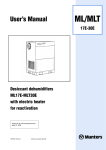
1
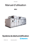
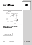
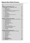
Original instructions
User’s manual
IceDry30
Desiccant dehumidifier
Applies to all units manufactured
from week 50, 2009
190TEN-1049-F0912
© Munters Europe AB 2009
Important user information
Intended use of equipment
Safety
Munters dehumidifiers are intended to be used for the
dehumidification of air. All other uses of the equipment,
or use which is contrary to the instructions given in
this manual, can cause personal injury and/or machine
damage
In this publication hazardous activities are indicated and
preceded by the common hazard symbol.
WARNING!
is used in this publication to indicate a possible danger that
could lead to personal injury. An instruction is normally given,
Warranty and obligations
The warranty period is 24 months from the date the
equipment left our factory, unless otherwise advised
in writing. The warranty is limited to a free exchange
including free freight of the faulty unit or components,
which have failed as a result of faulty quality or defects in
manufacture. Munters guarantees that the unit supplied
has undergone thorough testing to ensure that it meets
the specifications given here. All warranty claims must
include proof that the fault has occurred within the
warranty period and that the unit has been used in
accordance with the specifications. All claims must
specify the unit type and manufacturing number. This
information is stamped on the unit identification plate,
see the section Marking.
Note!
The contents of this publication can be changed without
prior notice. This publication contains information
which is protected by copyright laws. No part of this
publication may be reproduced, stored in a system for
information retrieval or be transmitted in any form, in
any manner without Munters’ written consent. Please
send any comments regarding the contents of this
publication to:
followed by a short explanation, plus the possible effects if
the instruction is not followed.
CAUTION!
is used in this publication to indicate a possible danger that
could lead to damage to the machine or other equipment
and/or cause environmental damage. An instruction
is normally given, followed by a short explanation, plus
the possible environmental effect if the instruction is not
followed.
NOTE! Used to accentuate supplementary information
that is required for problem-free use or optimal use of the
unit.
Conformity with directives and
standards
We Munters EuropeAB declare that the dehumidifier
is in conformity with the essential health and safety
requirements of the Machinery Directive 2006/42/EC,
the Low Voltage Directive 2006/95/EC and the
EMC Directive 2004/108/EC The dehumidifier
is manufactured by an ISO 9001:2008 accredited
manufacturing organisation.
Munters Europe AB
Dehumidification Division
Technical Documentation
P O Box 1150
SE - 164 26 KISTA Sweden
Tel: +46 8 626 63 00
e-mail: [email protected]
© Munters Europe AB 2010
ii
Important user information
190TEN-1049-F0912
Table of contents
Important user information . . . . . . . . . . . . . . .
ii
Operation . . . . . . . . . . . . . . . . . . . . . . . . . . . . . . . . . . . .
13
ii
3.1
General . . . . . . . . . . . . . . . . . . . . . . . . . . . . . . . .
13
ii
3.2
Safety . . . . . . . . . . . . . . . . . . . . . . . . . . . . . . . . . .
13
Note! . . . . . . . . . . . . . . . . . . . . . . . . . . . . . . . . . . .
ii
3.3
Quick stop . . . . . . . . . . . . . . . . . . . . . . . . . . . . . .
13
Safety . . . . . . . . . . . . . . . . . . . . . . . . . . . . . . . . . .
ii
3.4
Operating the unit . . . . . . . . . . . . . . . . . . . . .
13
3.4.2 Start . . . . . . . . . . . . . . . . . . . . . . . . . . . . .
14
Intended use of equipment . . . . . . . . . . .
Warranty and obligations . . . . . . . . . . . . .
3
Conformity with directives and
1
2
standards . . . . . . . . . . . . . . . . . . . . . . . . . . . . . .
ii
3.4.3 Stop . . . . . . . . . . . . . . . . . . . . . . . . . . . . .
14
Table of contents . . . . . . . . . . . . . . . . . . . . . . . . . . .
iii
3.4.4 Alarms . . . . . . . . . . . . . . . . . . . . . . . . . .
14
Introduction . . . . . . . . . . . . . . . . . . . . . . . . . . . . . . . . .
1
Defrosting . . . . . . . . . . . . . . . . . . . . . . . . . . . . . .
14
1.1
General . . . . . . . . . . . . . . . . . . . . . . . . . . . . . . . .
1
3.5.1 During operation . . . . . . . . . . . . . . .
1.2
About this manual . . . . . . . . . . . . . . . . . . . . .
1
15
1.3
Safety and Cautions . . . . . . . . . . . . . . . . . . .
3.5.2 During downtime . . . . . . . . . . . . . . .
1
15
1.4
Markings . . . . . . . . . . . . . . . . . . . . . . . . . . . . . . .
1
1.5
Supervision of operation . . . . . . . . . . . . . .
1.6
Fault indications . . . . . . . . . . . . . . . . . . . . . . .
Installation . . . . . . . . . . . . . . . . . . . . . . . . . . . . . . . . . . .
3
2.1
General . . . . . . . . . . . . . . . . . . . . . . . . . . . . . . . .
3
2.2
Safety . . . . . . . . . . . . . . . . . . . . . . . . . . . . . . . . . .
3
2.3
Moving the equipment . . . . . . . . . . . . . . . .
3
External electrical cabinet . . . . . . . . . . . .
16
Service and Maintenance . . . . . . . . . . . . . . . . . .
17
2
4.1
Safety . . . . . . . . . . . . . . . . . . . . . . . . . . . . . . . . . .
17
2
4.2
Regular service and maintenance . . .
17
4.3
Service options . . . . . . . . . . . . . . . . . . . . . . . .
18
4.4
Service and indicator lamp . . . . . . . . . . . .
18
4.4.1 Yellow lamp lights . . . . . . . . . . . . . .
18
4.4.2 Service requirements . . . . . . . . . .
18
2.4
Packaging and delivery inspection . . .
4
2.5
Storing the Equipment . . . . . . . . . . . . . . . .
4
2.6
Site requirements . . . . . . . . . . . . . . . . . . . . .
2.7
2.8
2.9
3.5
3.6
4
Service and Maintenance Schedule .
19
Fault tracing . . . . . . . . . . . . . . . . . . . . . . . . . . . . . . . . .
4.5
21
5
5.1
General . . . . . . . . . . . . . . . . . . . . . . . . . . . . . . . .
21
Where to install the dehumidifier . . . . .
5
5.2
Safety . . . . . . . . . . . . . . . . . . . . . . . . . . . . . . . . . .
Ducting . . . . . . . . . . . . . . . . . . . . . . . . . . . . . . . . .
21
5
5.3
Fault tracing list . . . . . . . . . . . . . . . . . . . . . . . .
2.8.1 General recommendations . . .
5
22
2.8.2 Process intake . . . . . . . . . . . . . . . . .
Dehumidifier design . . . . . . . . . . . . . . . . . . . . . . .
24
6
6.1
Product Description . . . . . . . . . . . . . . . . . . .
2.8.3 Dry air outlet duct . . . . . . . . . . . . . .
24
6
6.3
Principle of operation . . . . . . . . . . . . . . . . . .
2.8.4 Intake duct for reactivation air .
6
24
2.8.5 Ductwork for Wet Air Outlet . . . .
7
6.4
Dimensions and service space
5
6
requirements . . . . . . . . . . . . . . . . . . . . . . . . . .
24
6.5
Technical specifications . . . . . . . . . . . . . .
26
6.6
Main components . . . . . . . . . . . . . . . . . . . . .
26
6.7
Noise data . . . . . . . . . . . . . . . . . . . . . . . . . . . . .
28
Control system . . . . . . . . . . . . . . . . . . . . . . . . . . . . . .
29
7.1
General . . . . . . . . . . . . . . . . . . . . . . . . . . . . . . . .
29
7.2
Structure . . . . . . . . . . . . . . . . . . . . . . . . . . . . . . .
29
7.3
Working with the control system . . . . . .
29
7.4
Operating windows (windows 1-5) . . .
29
Installation example - cold-storage
room (freezer) . . . . . . . . . . . . . . . . . . . . . . . . .
8
2.9.1 Recommended installation
options . . . . . . . . . . . . . . . . . . . . . . . . . .
8
2.10 Electrical Connections . . . . . . . . . . . . . . . .
9
2.10.1Mains Supply . . . . . . . . . . . . . . . . . . .
10
2.10.2External cables . . . . . . . . . . . . . . . .
10
2.11 Pre-start settings . . . . . . . . . . . . . . . . . . . . . .
10
2.12 Pre-start checks . . . . . . . . . . . . . . . . . . . . . . .
10
2.12.1Pre-Start Checklist . . . . . . . . . . . .
11
2.13 Airflow Check and Adjustment . . . . . . .
12
2.13.1General . . . . . . . . . . . . . . . . . . . . . . . . .
12
190TEN-1049-F0912
7
Table of contents
7.4.1 Window 1, Reactivation
temperature . . . . . . . . . . . . . . . . . . . .
29
7.4.2 Window 2, Runtime . . . . . . . . . . . .
30
iii
7.4.3 Window 3, Motor status . . . . . . . .
31
operation . . . . . . . . . . . . . . . . . . . . . . .
7.4.4 Window 4, Reactivation
7.5
power . . . . . . . . . . . . . . . . . . . . . . . . . . .
31
7.4.5 Window 5, Alarm . . . . . . . . . . . . . . .
31
Basic settings (windows 10-12) . . . . . .
32
information . . . . . . . . . . . . . . . . . . . . .
32
7.5.3 Window 12, Defrosting during
downtime . . . . . . . . . . . . . . . . . . . . . . .
32
7.5.4 Window 12, Defrosting during
downtime . . . . . . . . . . . . . . . . . . . . . . .
7.5.1 Display 10, Software
iv
7.5.2 Display 11, Defrosting during
33
32
Table of contents
190TEN-1049-F0912
1
Introduction
1.1 General
Munters manufactures a wide range of dehumidifiers that are designed for different uses and applications.
Munters dehumidifiers are designed to dehumidify air efficiently. The unit is inspected and checked prior
to leaving the factory to guarantee consistent quality and maximum reliability. Please contact your nearest
Munters office if you have any questions regarding the installation of your dehumidifier.
For product data, see chapter 6, Dehumidifier design.
1.2 About this manual
This manual is written for the user of the dehumidifier and describes the installation, operation, maintenance
and basic fault finding.
The manual is divided into numbered chapters and sections. Contents on page 3 gives a quick overview.
Each chapter can be used separately. Figures and tables are numbered within each chapter.
Example: Figure 1-3 is figure number 3 in chapter 1.
1.3 Safety and Cautions
The contents of this manual include suggestions for best working practices and procedures. These are given
as guidance only and are not intended to replace individual responsibility and/or local safety regulations.
During installation and operation of this equipment, it is always each individual person’s responsibility to
consider:
■
Their own safety and that of others.
■
The safety of the unit through correct use of the equipment in accordance with the descriptions and
instructions given in this manual.
The dehumidifiers are designed to meet the safety requirements, directives and standards listed in the EC
Declaration of Conformity.
We recommend that the user learns the use of safety symbols in this manual by reading the Important User
Information section. Safety information is listed early in each chapter of this manual.
190TEN-1049-F0912
Introduction
1
1.4 Markings
Figure 1.1 Position of identification plate.
Type IceDry30
Fabr. No. 0914 190XXX XXXXX
Fabr. year 2009
3 ~ 400V 50 Hz
M
Max
4,56 kW
18 kW
22,6 kW
IP33
Made in Sweden
Munters Europe AB
Isafjordsgatan 1
164 26 Kista, Sweden
Figure 1.2 Identification plate, example.
Explanation of "Fabr. No" on the identification plate:
09 = year of manufacture, 14 = week of manufacture, 190XXX = article number, XXXXX = serial number
1.5 Supervision of operation
The dehumidifier is controlled and monitored from a control panel mounted on an external electrical
cabinet, see section 3.6, External electrical cabinet.
1.6 Fault indications
Any faults that arise are indicated through illumination of the red lamp on the control panel. For detailed
information, see section 7.4.5, Window 5, Alarm.
2
Introduction
190TEN-1049-F0912
2
Installation
2.1 General
IceDry 30 is intended for installation in cold stores. The unit is inspected and checked prior to leaving the
factory to guarantee consistent quality and maximum reliability. Follow the instructions carefully. Faulty
installation can result in serious operational disturbances.
If the unit is to be put into storage, see section 2.5, Storing the Equipment prior to installation.
2.2 Safety
WARNING!
The mains power supply is permanently connected to the main power switch of the unit. Adjustments,
maintenance and repairs must only be carried out by authorised personnel.
CAUTION!
The built-in heater requires a continuous power supply to prevent functional disorder. Only switch off the unit’s
main power switch in the event of an emergency.
WARNING!
The wet air outlet may sometimes get hot. To avoid burns from unintended contact, make sure it is insulated.
CAUTION!
Condensation is easily formed on the inside of the duct due to the high humidity of the reactivation air. To avoid
condensation, the ductwork must be insulated.
CAUTION!
The main power switch should be activated as soon as the unit has been installed. This allows the built-in heater to
operate and prevents internal ice formation.
CAUTION!
Before starting the unit, the reactivation and wet air inlets and outlets must be thoroughly checked. Any ice must be
removed. To avoid malfunction, it is important to have clear air passage throughout the ductwork.
CAUTION!
If the process airflow damper is fully open, the high cold air density in the cold-storage room could damage the
process air fan.
CAUTION!
The adjusted airflow must not exceed the rated airflow by more than 10 %, see section
2.13, Airflow Check and Adjustment. Failure to correctly adjust the process and reactivation airflows
could cause the unit to malfunction.
190TEN-1049-F0912
Installation
3
2.3 Moving the equipment
The dehumidifier is delivered on a pallet and must be handled carefully. All panel doors on the unit must
be closed during transport. Provided that the dehumidifier is still secured to its delivery pallet, it can be
moved using a forklift truck.
See section 6.4, Dimensions and service space requirements for information about weight .
2.4 Packaging and delivery inspection
1. Check the delivery against the packing list, consignment note, or other delivery documents and check
that everything is included and nothing is damaged
2. G3 filter cartridges for process and reactivation air are included in the delivery. One cartridge is mounted
on the dehumidifier process air inlet and one on the outside of the cold-storage room, in the reactivation
air inlet.
3. Contact Munters immediately if the delivery is not complete in order to avoid installation delays.
4. If the unit is to be put into storage prior to installation, see section 2.5, Storing the Equipment.
5. Remove all packing materials from the unit and check carefully to make sure that no damage has
occurred during transport.
6. Any visible damage must be reported in writing to Munters prior to the start of installation.
2.5 Storing the Equipment
The following is important if the dehumidifier is to be stored prior to installation:
■
Place the dehumidifier on a horizontal surface.
■
Do not remove the dehumidifier’s packaging.
■
Protect the dehumidifier from physical damage.
■
Store the dehumidifier under cover and protect from dust, frost, rain and aggressive contaminants.
4
Installation
190TEN-1049-F0912
2.6 Site requirements
The dehumidifier is adapted to operation inside cold stores. The permitted operational temperatures are
given in 6.5, Technical specifications.
It is important that the intended installation site meets the location and space requirements for the
equipment in order to achieve the best possible performance and facilitate servicing. Therefore, comply
with the recommended service spaces, see section 6.4, Dimensions and service space requirements.
NOTE! The unit must be removed from the cold store at certain service intervals. Extra cable may then be
needed for connection to the equipment cabinet.
2.7 Where to install the dehumidifier
When selecting where to install the unit, select a place where it may be of the least disturbance to the
cold-storage room activities, while allowing for maintenance work such as process filter replacement.
The dehumidifier must be placed so that there is no risk of the process intake and filter icing up. Ice normally
forms around the the cold store’s doors and air-locks, where warm, humid air flows in.
Install the dehumidifier in such a way that the reactivation air and wet air ducts are as short as possible. The
distance between the wet air outlet and the wall, in which grommets for reactivation air are made, must not
exceed 0.7 m.
If the dehumidifier is to be located in a corner it can be positioned with either of its long sides against the wall
to provide for the best possible duct installation.
Remember that the dry air outlet should be connected to an air distribution device installed
above the door/airlock in the cold-storage room/freezer, see illustrations in section
2.9.1, Recommended installation options.
The external electrical cabinet is available in two different versions:
■
For installation in temperatures -25 °C to +10 °C
■
For installation in temperatures +10 °C to +25 °C
2.8 Ducting
2.8.1 General recommendations
NOTE! Vibration reduction. If there is a need to for reduction of vibrations from the dehumidifier, contact Munters
for instructions. Refer to standard EN 1299+A1:2008.
Due to the cold surroundings and risk of freezing, it is vital that all ducting is installed according to
instructions. See also 2.9, Installation example - cold-storage room (freezer).
To facilitate easy transfer of the dehumidifier out of the cold-storage room for service, all duct connections
should be easily disassembled. Should the dehumidifier, despite this recommendation, be installed in such a
way that it cannot be easily removed for service, it is important that the minimum service space requirements
are met, see 6.4, Dimensions and service space requirements. A vapour-tight connection between the wall and the
duct is vital. Preferably, polyurethane foam should be used if the temperature is sufficiently high during
application.
190TEN-1049-F0912
Installation
5
When installing ductwork between the dehumidifier and the inlet and outlet connections, the following
recommendations should be observed:
■
The length of ductwork should be kept as short as possible to minimise static air pressure losses.
■
To maintain performance, all rigid process or reactivation air ductwork joints must be air and vapour
tight.
■
The design of the duct connections should facilitate easy disconnection of the unit for service outside
the cold-storage room.
■
Condensation easily builds up on the inside of the duct due to the high humidity of the reactivation air.
To avoid condensation, the ductwork must be insulated.
■
The process air ductwork should be insulated to prevent condensation from developing on the outside
of the duct whenever the temperature of the air within the duct falls below the dewpoint of the ambient
air through which the ductwork is routed.
■
The wet air leaving the dehumidifier will easily cause condensation on the inside of the duct walls due to
the high moisture content. This must be avoided by insulating the ducts.
■
Ensure that access for operation and servicing is not restricted when designing and installing ducting.
For more information, see section 6.4, Dimensions and service space requirements.
■
To reduce noise and/or vibration being transmitted along rigid ductwork, good quality, airtight flexible
connections should be fitted.
■
Ducts mounted directly onto the dehumidifier should be adequately supported to minimise the load and
stress due to the weight and movement of the ducting.
■
Dampers for balancing the air flow must be installed in the reactivation air inlet duct. Correct airflows
are essential for maintaining the operating efficiency of the unit. For airflow adjustment details, see
section 2.13, Airflow Check and Adjustment.
■
Process air pressure and flow are adjusted using the process air fan’s frequency converter. If this is the
case, it is not necessary to have a damper in the dry air duct.
■
The total resistance in the process and reactivation ductwork must not exceed the performance rating
of the fans fitted in the dehumidifier. For details of minimum available static pressure, see chapter
6.5, Technical specifications.
2.8.2 Process intake
The dehumidifier has an external filter box for the process air inlet. If there is a risk of the process air filter
icing up, a duct should be connected to retrieve process air from a dry location approx. 5-10 metres from the
door opening. The filter box can then be moved to the inlet side of the duct.
2.8.3 Dry air outlet duct
Channel out the dry air from the dehumidifier and distribute it so that it mixes with the warm, humid air that
normally enters the cold store above the doors and air-locks that are opened regularly. Install an adjustable
damper in the duct, see section 2.9, Installation example - cold-storage room (freezer).
2.8.4 Intake duct for reactivation air
Place the reactivation air intake and filter box outside the cold store. Mount the filter box directly on the wall.
The duct to the dehumidifier reactivation air intake should be at most 1.5 metres long, and must be insulated
to prevent ice build-up. This also applies to the section of duct passing through the wall. An adjustable
damper is installed in the duct.
6
Installation
190TEN-1049-F0912
To prevent the outgoing wet air humidifying the incoming reactivation air, the reactivation air intake must be
positioned at least 2 metres from the wet air outlet.
A. Reactivation air
B. Wet air
1. Filter box
B
2. Condensate drains
3. Vapour-tight grommet
Min.
2,0 m
3
2
A
~ 0,5 m
1
2
Figure 2.1 Inlet for reactivation air and outlet for wet air.
2.8.5 Ductwork for Wet Air Outlet
The wet air duct from the dehumidifier’s reactivation outlet must be made of plastic or another rust-resistant
material. It must be able to handle temperatures between -30 °C and 75 °C, be no more than 1.5 metres long
and be insulated to prevent ice formation. This also applies to the part of the duct passing through the wall.
The wet air leaving the dehumidifier will, due to high moisture content, condense on the inside duct walls.
Due to the low ambient temperature, there is a risk of ice formation. The wet air duct must therefore be
insulated.
190TEN-1049-F0912
Installation
7
Horizontal ducts must be installed with a slight decline (away from the dehumidifier) to drain away
possible condensation. The decline must be at least 2 cm/m of duct.
5 mm drain holes should be made at low points of the duct to prevent water accumulation in the duct.
To prevent the outgoing wet air from humidifying the incoming reactivation air, the wet air outlet must
be placed at least 2 metres from the reactivation inlet. See Figure 2.1 .
■
■
■
NOTE! Always drill the drain holes on the outside of the cold storage/freezer room wall.
CAUTION!
The wet air outlet may sometimes get hot. To avoid burns from unintended contact, make sure it is insulated.
2.9 Installation example - cold-storage room (freezer)
2.9.1 Recommended installation options
Munters recommends the following installations. If in doubt, contact Munters for advice.
Service and major overhaul requires that the dehumidifier can be removed from the cold-storage room. It
must also be easy to remove connections to rigid ductwork from the dehumidifier.
> 0,7 m
> 0,7 m
2-3m
Figure 2.2 Position behind screen.
8
Installation
190TEN-1049-F0912
5 - 10 m
> 0,7 m
> 0,7 m
Figure 2.3 Position far away from door / airlock.
> 0,7 m
5 - 10 m
Figure 2.4 Process air duct far away from door / air lock.
NOTE! The main switch for the dehumidifier should be activated as soon as the unit has been installed. This
allows the built-in heater to operate and prevents internal ice formation.
The openings of inlet and outlet ducts must be well sealed during installation and operation stops, when the
dehumidifier is normally switched off. This prevents ice formation in ducts and dehumidifier caused by
unintended ventilation and low temperature in the cold-storage room.
190TEN-1049-F0912
Installation
9
2.10 Electrical Connections
2.10.1 Mains Supply
The unit is designed for use with a three-phase AC supply, (3~200/230/380/400/415 V, 50 Hz alt.
3~230/380/440/460/480 V, 60 Hz). See Machine safety - Electrical equipment for machines,
EN 60204-1 section 5.1. All units are delivered complete with all internal cabling installed and configured to
the voltage and frequency given on the ID plate.
NOTE! Supply voltage must not vary more than 10% of the specified operating voltage.
The unit must be adequately connected to earth.
For connection details, refer to the ID plate , Electrical Circuit Diagrams or section 6.5, Technical specifications.
The power supply must only be connected to the external electrical cabinet, which also contains a control
system. The connection cable and main fuses must be suitable to the unit being installed.
2.10.2 External cables
The dehumidifier is connected to the external electrical cabinet via the supplied cables (about 10 m) with
marked connectors. A special bracket is provided for wall mounting the external electrical cabinet.
2.11 Pre-start settings
On delivery, the dehumidifier’s operational parameters are set for use in a cold store. A number of
alternatives, to minimise the risk of operational disturbance, can be set on initial start-up, se
The application does not require the connection of external sensors or external input/output signals.
2.12 Pre-start checks
WARNING!
The mains power supply is permanently connected to the main power switch of the unit. Adjustments,
maintenance and repairs must only be carried out by authorised personnel.
10
Installation
190TEN-1049-F0912
2.12.1 Pre-Start Checklist
Before starting the dehumidifier for the first time, ensure that the mains power supply is isolated from the
dehumidifier and carry-out the following checks:
1. Make sure that the mode selector switch on the dehumidifier is in the OFF position, see section
3.6, External electrical cabinet.
2. Make sure that the air intake filters are undamaged and properly fitted, and that all areas inside the unit
are clean and free from ice.
3. Visually inspect all ducting and duct connections to make sure that all connections have been correctly
installed and that there are no signs of damage to the system. Also check that all ducts are free from
obstacles blocking the air passage.
4. Check that the incoming power supply voltage is correct and that the cables are correctly connected.
5. After connecting the process fan to power, check its turning direction. Open the dehumidifier’s front
panel. Start the dehumidifier and check that the fan is turning. Switch off the dehumidifier and check the
fan just before it stops. Make sure it has a clockwise rotation.
6. Make sure that the unit’s power supply and main switch are on as soon as the unit has been installed in the
cold-storage room. If not, check if there is ice in the unit.
7. Set the damper for the reactivation airflow fully open.
8. Set the damper for the process airflow 50 % open.
CAUTION!
If the process airflow damper is fully open, the high cold air density in the cold-storage room could damage the
process air fan.
CAUTION!
Before starting the unit, the reactivation and wet air inlets and outlets must be thoroughly checked. Any ice must be
removed. To avoid malfunction, it is important to have clear air passage throughout the ductwork.
190TEN-1049-F0912
Installation
11
2.13 Airflow Check and Adjustment
2.13.1 General
Contact Munters if necessary to order dehumidifier installation and adjustment. The addresses for Munters
are found on the back of this manual.
CAUTION!
If the process and reactivation airflows are not properly adjusted, the unit may malfunction. Airflow may be set to
maximum 10% above the specified nominal value listed in section 6.5, Technical specifications.
1. By adjusting the dampers installed in the dry air outlet and reactivation air inlet ducts, the process and
reactivation airflows can be changed to the required setting.
2. Start the dehumidifier for approximately 8 minutes to allow the reactivation heater to reach its normal
operating temperature. See section 3.4, Operating the unit.
3. Check that the temperature difference between reactivation air downstream of the heater, and the
regeneration temperature is approx. 95 °C (tolerance limit is ± 5 °C).
4. If the temperature difference lies outside of the tolerance limit, the reactivation air damper can be
adjusted in small steps (which causes the temperature indicator to stabilise after each adjustment) until
reactivation temperature is within the specified tolerances.
Example:
Inlet air temperature (ti) = 15°C
Reactivation air temperature (tu)= 110°C
Temperature increase =95°C
12
Installation
190TEN-1049-F0912
3
Operation
3.1 General
The dehumidifier is equipped with an external electrical cabinet containing control panel, main power
switch, mode switch, display and indicator lamps.
The mode switch has two operating positions:
■
Position 0: No dehumification. The heater in the electrical cabinet and the reactivation heater is still in
operation to avoid ice formation. An automatic rotor defroster function may still be in operation, see
section 3.5.2, During downtime.
■
Position 1: Continuous operation and dehumidification. Automatic rotor defrosting is normal during
operation, see section 3.5.1, During operation.
In the case of a power cut, the dehumidifier will restart automatically when the power supply is restored.
3.2 Safety
CAUTION!
When starting for the first time or restarting after a service stop, the main switch must have been on for at least 12
hours before starting. This is necessary for full activation of the unit’s heater.
CAUTION!
Before starting the unit, the reactivation and wet air inlets and outlets must be thoroughly checked. Any ice must be
removed. To avoid malfunction, it is important to have clear air passage throughout the ductwork.
CAUTION!
To prevent damage to the fans, the unit must not be run for longer than a few minutes prior to setting-up the process
and reactivation airflows.
CAUTION!
The main power switch should only be used to stop the dehumidifier in an emergency. Since the reactivation fan
will also stop, considerable heat can build up in the reactivation heater, causing its high temperature protector to
trip, which can cause damage to components close to the heater.
CAUTION!
Do not turn off the main power switch. This could lead to ice and frost formation in the control panel and in the
dehumidifier, which would cause malfunction.
3.3 Quick stop
The mode switch is used to start and stop the unit in normal operation. In case of emergency, use the main
power switch on the electrical cabinet.
190TEN-1049-F0912
Operation
13
3.4 Operating the unit
CAUTION!
At initial start-up or when restarting after a service stop, the main power switch must have been on for at least 12
hours before starting. This is necessary for full activation of the unit’s heater.
CAUTION!
Before starting the unit, the reactivation and wet air inlets and outlets must be thoroughly checked. Any ice must be
removed. To avoid malfunction, it is important to have clear air passage throughout the ductwork.
3.4.2 Start
1. Turn the main power switch to position "1" and check that the display is illuminated. The three lamps on
the electrical cabinet should flash twice as a check of lamp function.
2. Turn the mode switch to position "1". Check that:
- The white lamp is on, which indicates that the unit is operating.
- The reactivation air fan and rotor drive motor have started, see section 7.4.3, Window 3, Motor status.
3. Leave the unit operating and check that:
- The temperature of the reactivation heater increases, see 7.4.1, Window 1, Reactivation temperature.
- The process fan starts when the wet air temperature reaches 40 °C.
3.4.3 Stop
1. Turn the mode switch to position "0". In order to dissipate any residual heat, the reactivation air fan
and the rotor drive motor will continue to run until the reactivation temperature has fallen below
approximately 50 °C.
2. Check that the reactivation air fan and the drive motor stop once the reactivation temperature has fallen
below approximately 50 °C. A few minutes delay is normal.
3.4.4 Alarms
All alarms stop the dehumidifier and triggers the red alarm lamp on the electrical cabinet. Do as follows:
1. Check the current alarm code on the control system display, see section 7.4.5, Window 5, Alarm. In the
event of several simultaneous alarms the display switches automatically between the alarm codes.
NOTE! Alarm codes are reset when the mode switch or main power switch is moved to
position "0". Always note the current alarm codes first.
2. Set the mode switch and main power switch to position "0" when working in the electrical cabinet
or dehumidifier. Remedy any faults.
3. Restart the dehumidifier.
3.5 Defrosting
The dehumidifier is delivered with the defrosting function activated. The dehumidifier is defrosted at
regular intervals, both in operation mode "1" and when the mode switch is in position “0”.
The function can be deactivated via the control system display; see section
7.5.2, Display 11, Defrosting during operation.
14
Operation
190TEN-1049-F0912
CAUTION!
Ask Munters for advice before switching off the defrosting function.
3.5.1 During operation
Defrosting during operation (mode switch in position "1") means that the process fan stops for a short time,
about twice a day, so that the rotor heats up. When the wet air temperature has increased to approximately 40
°C the process fan starts again.
3.5.2 During downtime
Defrosting during downtime (mode switch in position "0") means that the reactivation fan, heater and rotor
starts automatically and run for a short time until the wet air temperature has increased to approximately
40 °C.
190TEN-1049-F0912
Operation
15
3.6 External electrical cabinet
3
5
4
6
1
2
Figure 3.1 External electrical cabinet
Item
Description
Function
1
Main Power Switch
When the main power switch is in the ”0”
position, the unit is not powered beyond the
switch. When the main power switch is in the
”1” position, the dehumidifier can be started.
2
Control system
See chapter 7, Control system for information
about control system functions.
3
Mode switch
With the mode switch in position "1" the
dehumidifier operates continuously (full
capacity). When the mode switch is in the ”0”
position, the dehumidifier is switched off but
may continue to run until it has cooled down.
4
White lamp (RUN)
Illuminates when the unit dehumidifies.
5
Red lamp (ALARM)
Lights in the event of an alarm. See section
7.4.5, Window 5, Alarm for fault type.
6
Yellow lamp (SERVICE)
Lights up when the dehumidifier has been
running for a certain number of hours.
Maintenance must now be carried out, see
section 4.5, Service and Maintenance Schedule.
Table 3.1 Functions for external electrical cabinet.
16
Operation
190TEN-1049-F0912
4
Service and Maintenance
4.1 Safety
WARNING!
Adjustments, maintenance and repairs must only be carried out by qualified personnel.
CAUTION!
When starting for the first time or restarting after a service stop, the main switch must have been on for at least 12
hours before starting. This is necessary for full activation of the unit’s heater.
CAUTION!
Before starting the unit, the reactivation and wet air inlets and outlets must be thoroughly checked. Any ice must be
removed. To avoid malfunction, it is important to have clear air passage throughout the ductwork.
4.2 Regular service and maintenance
Munters’ dehumidifiers are designed for long-term, continuous usage with a high degree of reliability.
As with all machinery, regular service and maintenance is required to keep the dehumidifier in optimal
condition so that it works most efficiently.
Service and maintenance interval lengths are primarily determined by operating conditions and the
environment in which the unit is installed. For example, if the process air contains a lot of dust, preventative
maintenance should be carried out at shorter intervals. The same also applies if the dehumidifier works
intensively.
The dehumidifier is equipped with a service indicator in the control system. During installation and
commissioning, an estimate should be made of a suitable number of operating hours until the next service or
the date for the next service. This value is programmed by Munters’ personnel.
See section 4.5, Service and Maintenance Schedule for an example of a standard service and maintenance
program.
Periodic maintenance will ensure that the steam control components provide trouble-free operation.
The frequency of maintenance will be determined by the operating conditions and the quality of the steam
supply where the unit is installed.
190TEN-1049-F0912
Service and Maintenance
17
4.3 Service options
In addition to commissioning of the unit, it is possible to choose between four different standard
service options (A-D). The service options comprise service efforts indicated in section
4.5, Service and Maintenance Schedule.
S. Commissioning/start-up
A. Check and (if necessary) change of filter - general operational check.
B. Check and (if necessary) change of filter - general operational check, safety and temperature checks.
C. Check and (if necessary) change of filter - general operational check, safety and temperature checks.
Preventive replacement of component kits.
D. Check and (if necessary) change of filter - general operational check, safety and temperature checks.
Preventive replacement of component kits after 3 years and 6 years of operation.
The Service Department at Munters can propose a service plan adapted to suit the special conditions of a
specific installation, based on how the unit works and the type of environment.
4.4 Service and indicator lamp
4.4.1 Yellow lamp lights
The yellow service lamp indicates the need for a filter replacement or a comprehensive service.
Remove the filter cover and replace the filter if this is the cause.
4.4.2 Service requirements
If window 2 shows "Service 0000" or a negative value, the dehumidifier has reached the number of operating
hours where a general service is recommended. Contact Munters service department.
Window 2 shows the number of operating hours until the next service is needed. A minus sign before the
number of hours indicates that the service should already have been carried out.
18
Service and Maintenance
190TEN-1049-F0912
4.5 Service and Maintenance Schedule
Service level
S
A
B
Operating time in
0
4000
8000
0
6
12
18
24
30
36
42
Filter replacement and operational checks
X
X
X
X
X
X
X
X
Preventive inspection incl. safety check
X
X
X
Service work
A
C
A
B
A
12000 16000 20000 24000 28000
hours
Calendar time in
months
Capacity check, rotor inspection
X
X
X
Replacement of HTCO Thermostats
Inspect drive belt and backing rollers,
X
replace if necessary
Rotor drive motor replacement
Fan revision (impellers, motors, bearings)
Switch board - control box, operational
check
X
Check temperature control sensors
X
X
X
X
X
X
Rotor covers - rotor seals - connection
piece, replacement
Table 4.1 Service and maintenance schedule (0 - 28000 hours)
NOTE! The unit must be removed from the coldstore at service level C and D.
190TEN-1049-F0912
Service and Maintenance
19
Service level
Service work
D
Operating time in
A
B
A
C
A
B
A
D
32000 36000 40000 44000 48000 52000 56000 60000 64000
hours
Calendar time in
48
54
60
66
72
78
84
90
96
X
X
X
X
X
X
X
X
X
months
Filter replacement and operational
checks
Preventive inspection incl. safety check
X
Capacity check, rotor inspection
X
Replacement of HTCO Thermostats
X
Inspect drive belt and backing rollers,
Rotor drive motor replacement
Fan revision (impellers, motors,
bearings)
Switch board - control box, operational
Check temperature control sensors
Rotor covers - rotor seals - connection
piece, replacement
X
X
X
X
X
X
X
replace if necessary
check
X
X
X
X
X
X
X
X
X
X
X
X
X
X
X
X
X
X
X
Table 4.2 Service and maintenance schedule (32000 - 64000 hours)
NOTE! The unit must be removed from the coldstore at service level C and D.
20
Service and Maintenance
190TEN-1049-F0912
5
Fault tracing
5.1 General
The purpose of this chapter is to provide guidance in basic fault tracing and provide instructions for
corrective actions to remedy any faults. Wiring diagrams can be useful when fault finding.
5.2 Safety
WARNING!
Adjustments, maintenance and repairs must only be carried out by qualified personnel.
CAUTION!
When restarting after a service stop, the main switch must have been on for at least 12 hours before starting. This is
necessary for full activation of the unit’s heater.
CAUTION!
Before starting the unit, the reactivation and wet air inlets and outlets must be thoroughly checked. Any ice must be
removed. To avoid malfunction, it is important to have clear air passage throughout the ductwork.
190TEN-1049-F0912
Fault tracing
21
5.3 Fault tracing list
The red alarm lamp and the control system display constitute the primary source of information for fault
tracing when an alarm has been triggered and the unit has stopped.
See the wiring diagram for identification of electrical components in the separate control panel.
Fault symptom
Unit has stopped
Indicators
Lamps and display are off
Possible cause
Power supply failure
Corrective action
Check power supply to the
unit.
Main power switch (No.1) is
Move the main power switch
in position"0".
to position 1 and check that
the display is activated and
that the three lamps flash a
lamp test.
One or more automatic fuses
Investigate the cause of
FU 20-24 have been tripped.
the fault and rectify. Reset
fuses.
Circuit breaker QM 17
Investigate the cause of
tripped due to a wiring fault.
the fault and rectify. Reset.
If the fault recurs, contact
Munters.
Unit has stopped
The red lamp illuminates
Reactivation heater’s high
Leave the unit to cool down.
(alarm) and window 5 shows:
temperature cut-out BT35
Check that the air inlet, outlet
Alarm code No. 1
or BT35A has been tripped,
ducts and filters are free
either due to a block of
from obstructions and not
reactivation airflow or
clogged with dirt. Check
because the reactivation
and adjust the reactivation
airflow setting is too low.
airflow, see page 12.
Rotor has stopped.
Check that the drive belt is
Alarm code No. 2
intact.
Alarm code No. 3
Reactivation fan is not
working:
- the circuit breaker has
Reset QM15.
tripped
- contactor fault
22
Fault tracing
Check KM 32.
190TEN-1049-F0912
Fault symptom
Unit has stopped
Indicators
Alarm code No. 4
Possible cause
Corrective action
Process air fan
Investigate the
is not working:
reason and reset
- the circuit breaker has
QM 16.
tripped
Alarm code No. 5
Alarm code No. 6
Temperature too high in
Leave the motor to cool
drive motor
down and rectify the cause.
Reactivation heater is not
Reset QM 12, 13 or 14.
working
Alarm code No. 7
Reserve
Alarm code No. 8
Reserve
Alarm code No. 9
High temperature in
High temperature cut-out
reactivation fan heater. High
BT23 must be reset
temperature cut-out BT23
manually. It is located on
and/or BT37 has tripped.
the fan house within the
dehumidifier. To access,
remove the centre panel on
the dehumidifier.
Alarm code No. 10
External wiring not
Check that all external
connected
control panels and
dehumidifier connectors
are properly connected.
Loss of performance. The
None
The reactivation air
Check the function of the
dehumidifier is in operation
temperature is too low
reactivation heater.
but is not controlling the
according to
humidity.
display No. 1.
None
None
Reactivation and process
Check and adjust the
airflows do not correspond to
reactivation and process
the rated airflows.
airflow, see page 12.
Frost and ice build-up in the
Check that the automatic
rotor.
defrosting function is
working, see section
3.5, Defrosting.
Table 5.1 Fault tracing list
190TEN-1049-F0912
Fault tracing
23
6
Dehumidifier design
6.1 Product Description
The desiccant dehumidifiers in the IceDry series have been developed to effectively dehumidify the air in
cold stores in order to minimise frost and ice build-up.
The dehumidifier is equipped with an encapsulated rotor unit. The rotor casing is constructed of durable
thermoset plastic and contains isolated sections that provide a precise balance for the dehumidification,
reactivation and heat recovery airflows.
The electrical control system complies with the EN60204 (IEC60204) standards. The electrical components
are mounted on busbars and are made of halogen-free plastic. For operating temperature, see section
6.5, Technical specifications.
The dehumidifier is manufactured in accordance with uniform European standards and established
requirements for CE-marking.
6.3 Principle of operation
1. Process air
2. Dry air
3. Reactivation air
4. Wet air
4
2
3
1
Figure 6.1 Principle of operation
The desiccant rotor structure comprises a large number of narrow and parallel air channels, processed to a
composite material that is highly effective in attracting and retaining water vapour.
The rotor is exposed in sectors to different airflows. The airflow that is to be dehumidified is called process
air (1) and passes through the largest sector of the rotor. The moisture in the process air is deposited into the
rotor structure and the process air will then leave the rotor as dry air (2).
While the rotor rotates slowly the incoming process air always meets a dry rotor structure, thus creating a
continuous dehumidification process.
The airflow that is used to reactivate (dry) the rotor structure is called reactivation air (3) and is first
heated. Passing through the smallest sector of the rotor, in the opposite direction to the process airflow, the
reactivation air removes the deposited moisture and leaves the rotor as wet air (4) – warm, moist air.
24
Dehumidifier design
190TEN-1049-F0912
6.4 Dimensions and service space requirements
Y
Y
J
B
N
X
A
N
F
2
OD
4
OE
M
H
1
C
3
OD
G
L
P
K
P
Figure 6.2 Dimensions and service space requirements.
1. Process air inlet
2. Dry air outlet
3. Reactivation air inlet
4. Wet air outlet
Dimensions (mm)
Weight
(kg)
A
B
C
D
E
F
G
H
J
K
L
M
N
P
X(1)
Y(1)
Z(1)
1200
875
1425
315
200
568
460
756
608
50
460
424
48
438
200
900
700
260 + 25
(1) Space for service
600
Table 6.1 Dimensions and service space
600
215
Figure 6.3 Dimensions for external electrical cabinet.
190TEN-1049-F0912
Dehumidifier design
25
6.5 Technical specifications
Process air
Rated airflow (m3/s)
0,833
Rated airflow (m3/h)
3000
Minimum available static pressure (Pa)
300
Fan motor power (kW)
3,0
Reactivation air
Rated airflow (m3/s)
0,175
Rated airflow (m3/h)
630
Minimum available static pressure (Pa)
300
Fan motor power (kW)
1,55
Rated Current
Current (Amps/Phase) 3~ 50 Hz 200 V
79,2
Current (Amps/Phase) 3~ 60 Hz 200V
79,2
Current (Amps/Phase) 3~ 50 Hz 230 V
65,2
Current (Amps/Phase) 3~ 50 Hz 380 V
39,4
Current (Amps/Phase) 3~ 50 Hz 400 V
38,0
Current (Amps/Phase) 3~ 50 Hz 415 V
36,8
Current (Amps/Phase) 3~ 60 Hz 440 V
36,2
Current (Amps/Phase) 3~ 60 Hz 460 V
35,1
Current (Amps/Phase) 3~ 60 Hz 480 V
33,8
Reactivation Heater
Temperature increase across heater (°C)
95
Reactivation Heater Power (kW)
18
Other Technical Data
Operating range for dehumidifier, ambient temperature (°C)
-25 to 0
Operating range for external electrical cabinet, ambient temperature (°C)
– for mounting in cool area
-25 to +10
– for mounting in warm area
+10 to +25
Drive motor power (W)
10
Reactivation fan heater power (W)
85
Output, heater in electrical cabinet (W)
150
Air filtration (standard)
G3 (EU3)
Electrical protection standard, dust and water resistant (main casing)
IP33
Fan Motor Winding Insulation Class
Klass F
Drive Motor Winding Insulation Class
Klass F
High Temperature Cut-Out (°C)
160 +/- 5
Contactor coil, voltage (V AC)
230
Table 6.2 Technical specifications
26
Dehumidifier design
190TEN-1049-F0912
6.6 Main components
3
2
4
1
5
6
10
9
8
7
1. Rotor seal ring
6. Lower rotor cover
2. Rotor
7. Reactivation fan
3. Upper rotor cover
8. Process fan motor
4. Reactivation heater
9. External electrical cabinet
5. Rotor drive motor
10. Process air filter
190TEN-1049-F0912
Dehumidifier design
27
6.7 Noise data
The following noise data is for a standard dehumidifier. The IceDry30 does not exceed these values.
Noise for
Correction Kok dB at ISO-band centre frequency, Hz
dB(A)
Lwt
63
125
250
500
1000
2000
4000
8000
Duct 1
Na
101
-10
-2
-9
-13
-20
-22
-27
-33
Duct 2
Na
102
-3
-5
-13
-20
-20
-19
-21
-26
3Duct 1
Na
94
-5
-6
-5
-17
20
-21
-23
-27
4Duct 1
Na
88
-2
-6
-12
-25
-31
-31
-33
-35
Room
64
90
-1
-8
-14
-16
-20
-23
-26
-31
Noice paths to surrroundings
1. Ductwork for dry air
2. Ductwork for process air
3. Ductwork for reactivation air
4. Ductwork for wet air
Figure 6.4 Noice paths to equipment room
SYMBOLS
Lwt = Total noise level dB (rel. 10-12 W)
Lw = Noise power level in octave band dB (rel. 10-12 W)
Kok = Correction for calculating Lw (Lw = Lwt + Kok)
dB(A) = Rated noise level at 100m2 room absorption
28
Dehumidifier design
190TEN-1049-F0912
7
Control system
7.1 General
The dehumidifier is provided with a programmable control system, which can be adapted to a certain extent.
On delivery, the system is set to standard values for operation in a cold store.
Figure 7.1 Control system panel
7.2 Structure
The system comprises a number of windows for operation (windows 1-5) and basic settings (windows
10-12). Normally, the basic setting component is only used to set basic values in conjunction with the initial
start-up.
7.3 Working with the control system
Figure 7.2 Keypad
Press > or < to page forward or back between the different operating windows.
Hold < depressed for three seconds to shift to the window for basic settings. Then press > or < to page
forward or back between the different operating windows. Press ∨ or ∧ to change the set value.
If you cannot find your way back to the start point, switch off the unit using mode switch. When the unit has
stopped completely, switch off the main power switch and then switch it on again. This resets the system.
The DEL, ALT, ESC, OK keys are only used for basic programming and for configuring the control system
and must not be used during normal operation.
7.4 Operating windows (windows 1-5)
Window for monitoring only. No settings can be made here.
190TEN-1049-F0912
Control system
29
7.4.1 Window 1, Reactivation temperature
Displays operational status and current reactivation temperature (ーC). ON is indicated "001" and OFF by
"000".
Figure 7.3 Window 1
RUN
Operational status
R-TEMP
Reactivation temperature
7.4.2 Window 2, Runtime
This displays the total running time of the dehumidifier. The running time remaining before the next
scheduled maintenance service are also displayed here.
Figure 7.4 Window 2
RUNTIME
Total running time.
SERVICE
Remaining time until next service. A negative value indicates that service was not
carried out as recommended.
30
Control system
190TEN-1049-F0912
7.4.3 Window 3, Motor status
This provides a simple way to check the status (on/off) of the motors for the process and reactivation fans as
well as the drive motor (Off = +000, On = +001).
Figure 7.5 Window 3
PROCESS FAN
Process fan
REACT. FAN
Reactivation fan
DRIVE MOTOR
Drive motor
7.4.4 Window 4, Reactivation power
This shows the percentage of the total reactivation heater output being used at the time of the reading.
Figure 7.6 Window 4
HEATER
Reactivation output being used.
7.4.5 Window 5, Alarm
This indicates all alarms. The alarms are denoted by a number, which represents a specific function alarm.
For a description of the corrective action for each alarm, see 5.3, Fault tracing list.
If an alarm is activated, the red lamp on the control panel lights up. The alarm indication disappears
automatically when its cause is removed.
The dehumidifier always stops when an alarm is activated. The dehumidifier is equipped with the following
alarms:
1. Temperature too high, reactivation heater
2. Reactivation fan
3. Process air fan
4. Rotor drive motor
5. Reactivation heater
6. 7. 8. Temperature too high, reactivation fan heater
190TEN-1049-F0912
Control system
31
9. Connection with control panel cut
Figure 7.7 Window 5
7.5 Basic settings (windows 10-12)
Setting displays when commissioning or changing operating conditions. These can only be activated when
the mode switch is in position "0".
Hold down < for three seconds to switch to the basic setting displays.
Hold down < for three seconds or wait for 30 seconds to return to operating mode.
7.5.1 Display 10, Software information
This shows the software version of the control system. This number is most often needed when contacting
Munters.
Figure 7.8 Window 10
7.5.2 Display 11, Defrosting during operation
The required defrosting function is set here during operation.
Figure 7.9 Window 11
+000=No
Automatic defrosting not activated.
+001=Yes
Automatic defrosting activated (preset option, contact Munters before changing
this).
See also 3.5, Defrosting.
32
Control system
190TEN-1049-F0912
7.5.3 Window 12, Defrosting during downtime
The required defrosting function is set here during longer periods of downtime. See also 3.5, Defrosting.
Figure 7.10 Window 12
+000=No
Automatic defrosting not activated.
+001=Yes
Automatic defrosting activated (preset option, contact Munters before changing
this).
7.5.4 Window 12, Defrosting during downtime
The required defrosting function is set here during longer periods of downtime. See also 3.5, Defrosting.
Figure 7.11 Window 12
+000=No
Automatic defrosting not activated.
+001=Yes
Automatic defrosting activated (preset option, contact Munters before changing
this).
190TEN-1049-F0912
Control system
33
.
.
AUSTRIA
Munters Austria GmbH
Niederlassung Amstetten
Franz Pitzl
Ybbsstraße 14
3300 Amstetten
Austria
Tel: + 43 (0) 7472 / 620 07
Fax: + 43 (0) 7472 / 620 46
E-mail: [email protected]
Web: http://www.munters.at
DENMARK
Munters A/S
Ryttermarken 4
DK-3520 Farum
Denmark
Tel: +45 44 95 33 55
Fax: +45 44 95 39 55
E-mail: [email protected]
Web: http://www.munters.dk
ITALY
Munters Italy S.p.A
Divisione Deumidificazione
Strada Piani 2
I-18027 Chiusavecchia
IM
Italy
Tel: +39 0183 5211
Fax: +39 0183 521333
E-mail: [email protected]
Web: http://www.munters.it
SWEDEN
Munters Europe AB
Avfuktning
Isafjordsgatan 1, Kista Entré
S-164 26 Stockholm, Kista
Sweden
Tel: +46 8 626 63 00
Fax: +46 8 754 85 94
E-mail: [email protected]
Web: http://www.munters.se
BELGIUM
Munters - Sales Dehumidification Systems
Dehumidification
Ingberthoeveweg 3E
B-2630 Aartselaar
Belgium
Tel: +32 3 458 24 34
Fax: +32 3 458 24 33
E-mail: [email protected]
Web: http://www.muntersnv.be
FINLAND
Munters Oy
Lyhtytie 22
P O Box 36, FIN-00741
Helsinki
Finland
Tel: +358 9 83 86 030
Fax: +358 9 83 86 03 36
E-mail: [email protected]
Web: www.munters.fi
NETHERLANDS
Munters Vochtbeheersing
Energieweg 69
NL-2404 HE Alphen a/d Rijn
Alphen a/d Rijn
Netherlands
Tel: +31 172 43 32 31
Fax: +31 172 44 29 60
E-mail: [email protected]
Web: http://www.munters.nl
SWITZERLAND
Munters GmbH
Luftentfeuchtung
Zweigniederlassung Effretikon
Im Langhag 11
CH-8307 Effretikon
Switzerland
Tel: +41 52 343 88 86
Fax: +41 52 343 88 87
E-mail: [email protected]
Web: http://www.munters.ch
BELGIUM
Munters Belgium SA
Zoning Industriel des Plenesses
Rue de Progrès 5
B-4821 Dison
Belgium
Tel: +32 87 30 69 11
Fax: +32 87 31 44 76
E-mail: [email protected]
Web: http://www.muntersbelgium.be
FRANCE
Munters France SAS
Dehumidification
17, rue de la Voie des Bans
F-95815 Argenteuil Cedex
France
Tel: +33 1 34 11 57 57
Fax: +33 1 34 11 57 58
E-mail: [email protected]
Web: http://www.munters.fr
POLAND
Munters Poland Sp. z.o.o.
Oddzial w Polsce
Dehumidification
ul. Litewska 3/4
P-80-719 Gdansk
Poland
Tel: +48 58 305 35 17
Fax: +48 32 660 11 23
E-mail: [email protected]
Web: http://www.munters.pl
UNITED KINGDOM
Munters Ltd
Dehumidification
Blackstone Road
Huntingdon PE29 6EE
Cambs
United Kingdom
Tel: +44 1480 432 243
Fax: +44 1480 413 147
E-mail: [email protected]
Web: http://www.munters.co.uk
CZECH REPUBLIC
MUNTERS CZ, organizacní složka
Holandská 2/4
CZ-639 00 BRNO
Czech Republic
Tel: +420 544 211 434
Fax: +420 544 211 436
E-mail: [email protected]
Web: http://www.munters-odvlhcovani.cz
GERMANY
Munters GmbH
Luftentfeuchtung
Zentrale
Hans-Duncker-Str. 8
D-21035 Hamburg
Germany
Tel: +49 40 734 16 01
Fax: +49 40 734 16 131
E-mail: [email protected]
Web: http://www.munters.de
SPAIN
Munters Spain SA
Deshumidificación
Europa Epresarial. Edificio Londres.
C/ Playa de Liencres 2. Edificio Londres
28230 Las Matas. Madrid
Madrid
Tel: +34 91 640 09 02
Fax: +34 91 640 11 32
E-mail: [email protected]
Web: http://www.munters.es
AUSTRALIA
Tel:+61 288431588
[email protected]
INDIA
Tel:+91 20 668 18 900
[email protected]
SINGAPORE
Tel:+65 6744 6828
[email protected]
UAE (Dubai)
Tel:+971 4 881 3026
[email protected]
BRAZIL
Tel:+55 41 3317 5050
[email protected]
JAPAN
Tel:+81 3 5970 0021
[email protected]
SOUTH AFRICA
Tel:+27 11 997 2000
[email protected]
USA
Tel:+1 978 241 1100
[email protected]
CANADA
Tel: +1 905 858 5851
[email protected]
KOREA
Tel:+82 2 761 8701
[email protected]
THAILAND
Tel:+66 2 642 2670
[email protected]
CHINA
Tel: +86 10 804 18000
[email protected]
MEXICO
Tel:+52 722 270 40 29
[email protected]
TURKEY
Tel:+90 212 286 18 38
[email protected]
www.munters.com