1
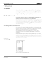
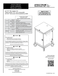
User’s Manual
ML/MLT
17E-30E
Desiccant dehumidifiers
ML17E-MLT30E
with electric heater
for reactivation
Applies to all units manufactured from
week 37, 2005
190TEN-1041revC
© Munters Europe AB 2005
Table of Contents
Important user information .................................. 5
1
2
3
Introduction ....................................................
1.1
General .................................................
1.2
About this manual .................................
1.3
Safety and caution measures ................
1.4
Markings ...............................................
1.5
Supervision of operation .......................
1.6
Fault indications ....................................
7
7
7
7
7
8
8
Installation ......................................................
2.1
General .................................................
2.2
Safety ....................................................
2.3
Moving the equipment ...........................
2.4
Packaging and Delivery Inspection. ......
2.5
Storing the Equipment ..........................
2.6
Location requirements ..........................
2.7
Ducting ..................................................
2.7.1 General recommendations .........
2.7.2 Ductwork for Outdoor Air Inlet ....
2.7.3 Ductwork for Wet Air Outlet ........
2.8
Precautionary measures for units using
LI desiccant rotor ..................................
2.9
Electrical Connections ..........................
2.9.1 Mains Supply ..............................
2.10 External humidity transmitter ................
2.10.1 Location requirements ................
2.11 Pre-start settings ...................................
2.11.1 Remote start ..............................
2.11.2 Continuous process air fan
operation ....................................
2.11.3 Humidity control alternatives ......
2.11.4 Reactivation temperature ...........
2.11.5 Control accuracy ........................
2.12 Pre-start checks ....................................
2.12.1 Pre-Start Checklist .....................
2.13 Airflow Check and Adjustment ..............
2.13.1 General ......................................
2.13.2 Process fan speed control (IP
version only) ...............................
9
9
9
9
10
10
10
11
11
12
12
Operation ........................................................
3.1
General .................................................
3.2
Safety ....................................................
3.3
Quick stop .............................................
3.4
Operating the unit .................................
3.4.1 Initial start-up, Manual mode
(100%) ........................................
3.4.2 Inital start-up, Automatic mode
(AUTO) - regulating to set-point ..
19
19
19
19
20
190TEN-1041revC a163
14
14
14
14
15
15
15
15
15
16
16
16
16
17
17
18
20
20
3.5
3.4.3 Inital start-up, Automatic mode
(AUTO) - external control ........... 21
Control Panel ........................................ 22
4
Service and Maintenance ..............................
4.1
Safety ....................................................
4.2
Regular service and maintenance ........
4.3
Service indicator lamp ..........................
4.3.1 Filter change needed .................
4.3.2 Service requirements .................
4.4
Service and Maintenance Schedule .....
24
24
24
24
24
24
25
5
Fault
5.1
5.2
5.3
Finding ..................................................
General .................................................
Safety ....................................................
Fault Finding .........................................
26
26
26
26
6
Dehumidifier design ......................................
6.1
Product Description ...............................
6.2
IP version ..............................................
6.3
Principle of operation ............................
6.4
Operating principles, IP version ............
6.5
Dimensions and service space
requirements .........................................
6.6
Capacity Diagrams ................................
6.7
Technical specifications ........................
6.8
Unit’s main components ........................
6.9
Noise data .............................................
28
28
28
28
29
Control system ACD ......................................
7.1
General .................................................
7.2
Structure ...............................................
7.3
Working with the ACD ...........................
7.4
Operating windows (1-6) .......................
7.4.1 Window 1A, Internal set-point ....
7.4.2 Window 1B, External set-point ....
7.4.3 Window 1C, External control ......
7.4.4 Window 1D, Extra set-point ........
7.4.5 Window 2, Runtime ....................
7.4.6 Window 3, Reactivation
temperature ................................
7.4.7 Window 4, Motor status ..............
7.4.8 Window 5, Reactivation power ....
7.4.9 Window 6, Alarm ........................
7.5
Basic settings (Windows 10-16) ............
7.5.1 Window 10, Information .............
7.5.2 WIndow 11, Continual operation
of process air fan ........................
7.5.3 Window 12, Humidity control
alternatives .................................
35
35
35
35
36
36
37
37
37
38
7
Table of Contents
30
31
32
33
34
38
39
39
39
40
40
41
41
iii
7.5.4 Window 13, Reactivation
temperature ................................
7.5.5 Window 14, Control accuracy .....
7.5.6 Window 15, P-gain .....................
7.5.7 Window 16, Integral time
constant ......................................
8
iv
8.2
41
42
42
8.3
8.4
8.5
Installation and operation ......................
8.2.1 General recommendations .........
Connecting the humidity transmitter .....
Maintenance .........................................
Dimensions ...........................................
44
44
44
45
45
43
HS21 Humidity transmitter ........................... 44
8.1
General ................................................. 44
Table of Contents
190TEN-1041revC
Important user information
Intended use of the equipment
Munters dehumidifiers are intended to be used for the
dehumidification of air. All other uses of the equipment,
or use which is contrary to the instructions given in this
manual, can cause personal injury and/or machine damage.
Safety
In this publication hazardous activities are indicated and
preceded by the common hazard symbol.
WARNING!
is used in this publication to indicate a
possible danger that could lead to personal
injury. An instruction is normally given,
followed by a short explanation, plus the
possible effects if the instruction is not
followed.
Warranty and obligations
The warranty period is 24 months from the date the
equipment left our factory, unless otherwise advised in
writing. The warranty is limited to a free exchange
including free freight of the faulty unit or components,
which have failed as a result of faulty quality or defects in
manufacture.
Munters guarantees that the unit supplied has undergone
thorough testing to ensure that it meets the specifications
given here. All warranty claims must include proof that
the fault has occurred within the warranty period and that
the unit has been used in accordance with the
specifications. All claims must specify the unit type and
manufacturing number. This information is stamped on
the unit identification plate, see the section Marking.
CAUTION!
is used in this publication to indicate a
possible danger that could lead to damage
to the machine or other equipment and/or
cause environmental damage. An
instruction is normally given, followed by
a short explanation, plus the possible
environmental effect if the instruction is
not followed.
Note!
The contents of this document can be changed without
prior notice.
This publication contains information which is protected
by copyright laws. No part of this publication may be
reproduced, stored in a system for information retrieval,
or be transmitted in any form or in any matter, without
Munters’ written consent.
Please send any comments regarding the contents of this
publication to:
Munters Europe AB
Dehumidification Division
Technical Publications
Box 434
191 24 Sollentuna
Sweden
Tel: +46 (0)8-626 63 00
Fax: +46 (0)8-626 86 18
© Munters Europe AB 2005
190TEN-1041revC
NOTE!
Used to accentuate supplementary
information that is required for
problem-free use or optimal use of the unit.
Conformity with directives and standards
Munters dehumidifiers are designed and manufactured by
an EN-ISO 9001 accredited development and
manufacturing organization. The unit conforms with the
specifications in the Machinery Directive 98/37/EEC,
the Low Voltage Directive 73/23/EEC, as amended by
Directive 93/68/EEC, and the EMC Directive
89/336/EEC as amended by Directives 92/31/EEC and
93/68/EEC. The standards applied are listed in the EC
Declaration of Conformity.
Important user information
5
This page left intentionally blank
Dehumidifier ML17E-MLT30E
1 Introduction
1.1 General
Munters dehumidifiers are designed to dehumidify air efficiently. Munters
manufactures a wide range of dehumidifiers that are designed for different
uses and applications. Please contact your nearest Munters office if you have
any questions regarding the installation of your dehumidifier.
For product data, see chapter 6, Dehumidifier design.
1.2 About this manual
This manual is written for the user of the dehumidifier and describes the
installation, operation, maintenance and basic fault finding.
The information structure of the manual is built on numbered chapters and
sections. Contents on page 3 gives a quick overview. The different chapters
can be used separately to serve their purpose. Figures and tables are numbered
in accordance with the actual chapter, e.g. figure 1–3 is picture number 3
and is found in chapter 1.
1.3 Safety and caution measures
The contents of this manual include suggested best working practices and
procedures. These are provided for guidance only. They are not intended to
replace personal responsibility and/or local safety regulations.
The dehumidifiers in the ML range are designed to meet the safety
requirements, directives and standards listed in the EC Declaration of
Conformity.
We recommend that the user informs him/herself about the use of safety
symbols in this manual by reading the section “Important User Information”
on the previous page . Safety information in this manual is contained at the
beginning of each of its chapters.
1.4 Markings
Figure 1.1 Location of the unit identification plate
190TEN-1041revC
1 Introduction
7
Dehumidifier ML17E-MLT30E
Type ML17E
Fabr. No 0537 190XXX XXXXX
3 ~ 400V 50Hz
M
Max
3,1 kW
18 kW
21,5 kW
IP54
Munters Europe AB
Figure 1.2 Main identification label, example
Explanation of "Fabr. no" on the identification plate
05 = year of manufacture, 37 = week of manufacture, 190XXX XXXXX = article
number
1.5 Supervision of operation
The dehumidifier is controlled and monitored using the control panel located
on the front of the unit,see section 3.5, Control Panel.
1.6 Fault indications
The red lamp on the control panel lights to indicate the occurrence of a fault.
Window 6 of the control system, see section 7.4.9, Window 6, Alarm. shows
which function caused the fault indication.
8
1 Introduction
190TEN-1041revC
Dehumidifier ML17E-MLT30E
2 Installation
2.1 General
The ML Dehumidifier is intended for indoor installation.
The unit is inspected and checked prior to leaving the factory to guarantee
consistent quality and maximum reliability.
If the unit is to be put into storage, prior to installation see section 2.5, Storing
the Equipment.
2.2 Safety
WARNING!
Ensure that the mains power is disconnected from the dehumidifier prior to changing the
orientation of the process and dry air connections.
WARNING!
Low voltage is permanently connected to the inlet main power switch of the unit. In the
event of adjustment, maintenance or repair, the unit front covers may only be removed by
qualified personnel.
CAUTION!
The wet air ducting must always be insulated if there is a risk of freezing. The wet air
leaving the dehumidifier will, due to high moisture content, condense on the inside duct
walls.
CAUTION!
The main power switch must only be used in an emergency to stop the unit. Since the
reactivation fan will also stop, considerable heat can develop in the reactivation heater
causing its high temperature protector to trip. Components close to the heat could be
damaged.
CAUTION!
The dehumidifier has been designed to operate at specific process airflows (corresponding
to the fan sizes installed) and must not be directly connected to air-conditioning systems.
2.3 Moving the equipment
The dehumidifier is delivered on a pallet and must be handled carefully. All
panel doors on the unit must be closed during transport. Provided that the
dehumidifier is still secured to its delivery pallet, it can be moved using a
fork-lift truck.
Weight of the dehumidifier can be found in section 6.5, Dimensions and service
space requirements.
190TEN-1041revC
2 Installation
9
Dehumidifier ML17E-MLT30E
2.4 Packaging and Delivery Inspection.
1 Check the delivery against the packing list, consignment note, or other
delivery documents and check that everything is included and nothing is
damaged.
2 Contact Munters immediately if the delivery is not complete in order to
avoid installation delays.
3 If the unit is to be put into storage, prior to installation, see section 2.5,
Storing the Equipment.
4 Remove all packing materials from the unit and check carefully to make
sure that no damage has occurred during transport.
5 Any visible damage must be reported in writing to Munters prior to the
start of installation.
2.5 Storing the Equipment
The following is important if the dehumidifier is to be stored prior to
installation:
Place the dehumidifier on a horizontal surface.
Do not remove the dehumidifier's packaging.
Protect the dehumidifier from physical damage.
Store the dehumidifier under cover and protect from dust, frost, rain and
aggressive contaminants.
2.6 Location requirements
The dehumidifier is only intended for indoor installation.
Avoid installing the dehumidifier in a damp environment where there is a
risk of water entering the unit or in a very dusty environment. If in doubt,
seek advice from Munters.
It is important that the intended installation site meets the location and space
requirements for the equipment in order to achieve the best possible
performance and trouble-free operation.
For the unit and service dimensions, see section 6.5, Dimensions and service
space requirements.
NOTE!
10
It is important, both for maintenance and for service, that the minimum dimensions for
service access are complied with.
2 Installation
190TEN-1041revC
Dehumidifier ML17E-MLT30E
2.7 Ducting
2.7.1 General recommendations
The connections for process and reactivation air are designed in accordance
with the recommendations in ISO 7807. The rectangular duct connections
contain tapped inserts for M8 screws.
NOTE!
The dehumidifier has been designed to operate at specific process airflows (corresponding
to the fan sizes installed) and must not be directly connected to air-conditioning systems.
NOTE!
The IP version, see section 6.2, IP version, does not have a process air filter. Process air
must therefore be connected to cold/pre-cooled and filtered air via a duct.
When installing ductwork between the dehumidifier and the inlet and outlet
connections, the following recommendations should be observed:
The length of ductwork should be kept as short as possible to minimise
static air pressure losses.
To maintain performance, all rigid process or reactivation air ductwork
joints must be air and vapour tight.
The process air ductwork should be insulated to prevent condensation
from developing on the outside of the duct whenever the temperature of
the air within the duct falls below the dewpoint of the ambient air through
which the ductwork is routed.
The ducting must always be insulated when there is a risk of freezing.
The wet air leaving the dehumidifier will easily cause condensation on the
inside of the duct walls due to the high moisture content. This must be
avoided by insulating the ducts.
Horizontal duct-runs should be installed sloping downwards (away from
the dehumidifier) to allow for condensate drainage. On the wet air outlet
ducting, suitable condensate drains should be installed at low points in
the ductwork. See figure 2.2, Wet air outlet design.
Ensure that access for operation and servicing is not restricted when
designing and installing ducting. For more information, refer to section
6.5, Dimensions and service space requirements.
To reduce noise and/or vibration being transmitted along rigid ductwork,
good quality, airtight flexible connections should be fitted.
Ducts mounted directly onto the dehumidifier should be adequately
supported to minimise the load and stress due to the weight and movement
of the ducting.
Dampers for balancing the airflows must be installed in the dry air outlet
and reactivation air inlet ducts. The correct airflows are essential for
190TEN-1041revC
2 Installation
11
Dehumidifier ML17E-MLT30E
maintaining the operating efficiency of the unit. To correct the airflow,
see section 2.13, Airflow Check and Adjustment.
For the IP version, see section 6.2, IP version process air pressure and flow
are adjusted using the frequency converter of the process air fan. In this
case, there is no need for a damper in the dry air duct.
The total resistance in the process and reactivation ductwork must not
exceed the performance rating of the fans fitted in the dehumidifier. For
details of minimum available static pressure, see section 6.7, Technical
specifications.
2.7.2 Ductwork for Outdoor Air Inlet
When bringing outside ambient air into the dehumidifier, the opening to the
inlet duct should be located sufficiently high above ground level to prevent
the pick-up of dust and debris. The ducting should be designed to prevent
rain and snow from being drawn into the dehumidifier. The air inlet must
be located away from possible contaminant such as engine exhaust gases,
steam and harmful vapours.
To prevent the wet (outlet) air humidifying the reactivation (inlet) air, the
air inlet for reactivation must be located at least 2 m from the air outlet for
wet air. See figure 2.1, Outdoor air inlet design.
Rectangular duct
Round duct
Wire netting, mesh width
approx. 10 mm
Wire netting, mesh width
approx. 10 mm
Figure 2.1 Outdoor air inlet design
2.7.3 Ductwork for Wet Air Outlet
Wet air ducting should be manufactured in corrosion-resistant material (e.g.
stainless steel, aluminium or plastic) and should be capable of withstanding
temperatures of up to 100ーC.
NOTE!
The wet air ducting must always be insulated if there is a risk of freezing. The wet air
leaving the dehumidifier will easily cause condensation on the inside of the duct walls due
to the high moisture content.
Horizontal duct-runs must therefore be installed sloping downwards (away
from the dehumidifier) to allow for condensate drainage. The slope should
be a minimum of 2 cm per meter of duct. In addition, 5 mm drain holes
12
2 Installation
190TEN-1041revC
Dehumidifier ML17E-MLT30E
should be drilled at the lowest points in the ducting to prevent water
accumulating in the duct, see figure 2.2, Wet air outlet design.
Horizontal
wet air outlet
Vertical
wet air outlet
Downward slope
away from dehumidifier
Wet air
Wire netting, mesh width
approx. 10 mm
Wet air
Wire netting, mesh width
approx. 10 mm
To condensate drain
Figure 2.2 Wet air outlet design
5
B
B
1
C
4
5
2
A
A
D
3
A
Process air inlet
1
Dry air damper
B
Dry air outlet
2
External filter box (optional)
C
Reactivation air inlet
3
Duct transition
D
Wet air outlet
4
Reactivation air damper
5
Outlet duct (wire netting)
Figure 2.3 Ducts required for installation. The illustration on the left depicts the IP version with
pre-cooling.
190TEN-1041revC
2 Installation
13
Dehumidifier ML17E-MLT30E
2.8 Precautionary measures for units using LI desiccant rotor
The dehumidifier comes standard with Munters' high performance rotor
HPS (High Performance Silicia gel).
If the dehumidifier is delivered with LI rotor (lithium chloride) it is vital to
prevent the desiccant rotor from becoming to greatly loaded with moisture
when the dehumidifier is switched off. Make sure that no air passing through
the rotor has a relative humidity greater than 80% !
We recommend installation of an adjustment damper in the dehumidifier's
process and reactivation air inlet. This prevents air with very high relative
humidity from inadvertently being drawn through the rotor and into the
room.
This is particularly important when the process air is drawn from outdoors,
or the system has been fitted with a pre-cooler.
2.9 Electrical Connections
2.9.1 Mains Supply
The unit is designed for 3-phase AC operation. Each unit is supplied complete
with all the internal wiring installed and configured in accordance with the
specified voltage and frequency on the identification plate.
NOTE!
The supply voltage must not differ by more than 10% from the specified operating voltage.
The unit must be correctly earthed.
The mains power supply is connected directly to the main power switch in
the unit. The supply cable and main fuses must be dimensioned to suit the
unit being installed.
For connection details, refer to the identification plate and Electrical Circuit
Diagram or refer to section 6.7, Technical specifications.
2.10 External humidity transmitter
The dehumidifier is supplied as standard with a humidity transmitter of type
HS21 suitable for wall of duct mounting. This is mounted externally and
connected to a terminal block, see the electrical circuit diagram supplied with
the unit. The humidity transmitter controls the dehumidifier when the
operational mode switch is in the AUTO position, i.e. automatic operation,
and also indicates the current Relative Humidity, see section 2.11, Pre-start
settings.
To ensure functionality, the humidity transmitter should be connected using
the cable supplied. If a longer cable is required, use of the same cable type
is recommended. If the transmitter cable is longer than approx. 100 metres,
there may be voltage drops that could affect the function of the humidity
transmitter.
14
2 Installation
190TEN-1041revC
Dehumidifier ML17E-MLT30E
2.10.1 Location requirements
The humidity transmitter should be mounted 1–1.5 m above the floor and
positioned so that it is not exposed directly to dry air from the unit or
incoming moist air from opening and closing doors. It must not be placed
close to a heat source or so that is it is exposed to direct sunlight.
2.11 Pre-start settings
Before starting the dehumidifier for the first time, a number of operating
parameters must be set via the ACD control system; see section 7.5, Basic
settings (Windows 10-16). Some features require connection to external
equipment. For wiring details, refer to the wiring diagrams supplied with this
unit.
2.11.1 Remote start
The unit can be started and stopped externally with a switch connected
between terminal blocks 307 and 308. To do so, the link that is mounted as
standard must be removed.
2.11.2 Continuous process air fan operation
The default setting is that the process fan starts automatically only when
dehumidification is needed. However, continuous process airflow may be
desirable even when there is no demand for dehumidification.
The process fan can be set to operate continuously, see section 7.5.2, WIndow
11, Continual operation of process air fan.
2.11.3 Humidity control alternatives
There are three different ways of controlling the dehumidifier when in the
automatic operational mode, see section 7.5.3, Window 12, Humidity control
alternatives.
1 The dehumidifier runs to an internally adjustable set-point which is
programmed via control system window 1A.
2 The dehumidifier is regulated to an externally adjustable set-point. See
display 1B. The external set-point comprises an analogue signal, 0-10 V,
between terminal blocks 304 and 306. 3.0 volts, for example, is set-point
30% RH.
3 The dehumidifier's heater is controlled from an external input signal, 0-10
V, see display 1C. The external input signal at input 18 (terminal block
306) controls the heater power regardless of the actual humidity load. 3.0
volt, for example, means that the unit is being run at approximately 30 %
heating capacity
If you can accept a different relative humidity level during certain times,
then it is possible, regardless of which of these three control alternatives
is selected, to control the dehumidifier against an additional temporary
internally adjustable set value, designated set value 2, see section 7.4.4,
Window 1D, Extra set-point. Set value 2 is activated using a closing contact,
190TEN-1041revC
2 Installation
15
Dehumidifier ML17E-MLT30E
which might be a timer, for example, between terminal blocks 309 and
310.
2.11.4 Reactivation temperature
It is possible to set a maximum reactivation temperature. It is pre-set to
130°C, see section 7.5.4, Window 13, Reactivation temperature.
2.11.5 Control accuracy
It is also possible to set the maximum difference between switching on and
off, so-called hysteresis, in display 14.The pre-set value is 3 %. For more
information, see section 7.5.5, Window 14, Control accuracy.
2.12 Pre-start checks
WARNING!
The mains power supply is permanently connected to the main power switch in the unit.
Adjustments, maintenance and repair work may only be carried out by qualified personnel.
2.12.1 Pre-Start Checklist
The following checks are to be carried out before the dehumidifier is started
for the first time.
1 Ensure that the main power switch on the control panel is in the position
0.
2 Check the air intake filters for damage and proper fixation and also check
that all areas inside the unit are clean.
3 Visually inspect all ducting and duct connections to make sure that all
connections have been correctly installed and that there are no signs of
damage to the system. Also check that all ducts are free from obstacles
blocking the air passage.
4 Remove the lower front panel and check that none of the circuit breakers
on the control panel has tripped. For further details, refer to the wiring
diagrams provided with the unit.
5 Check that the incoming power supply voltage is correct and that the
cables are correctly connected.
6 Check that the humidity transmitter/sensor have been correctly positioned
in the room and have been properly connected to the unit, see section
2.10, External humidity transmitter.
7 Set the process and reactivation airflow dampers to the fully open position.
For the IP version, the process air fan is run at high speed with the help
of the frequency converter, see section 2.13.2, Process fan speed control (IP
version only)
16
2 Installation
190TEN-1041revC
Dehumidifier ML17E-MLT30E
2.13 Airflow Check and Adjustment
2.13.1 General
To obtain the design performance, the dry air and reactivation airflow
dampers must be correctly adjusted in accordance with the rated airflow, see
section 6.7, Technical specifications.
If necessary, please contact Munters to obtain help to order the installation
and adjustment of the dehumidifier. The addresses and telephone numbers to Munters
can be found on the back of this manual.
CAUTION!
Failure to correctly adjust the process and reactivation airflows could cause the unit to
malfunction.
1 The direction of rotation of the rotor must be checked after connection
to the power supply. Open the middle front panel. Start the dehumidifier
and check that the rotor is rotating clockwise, i.e. in the same direction
as the arrow.
2 By adjusting the dampers installed in the dry air outlet and reactivation
air inlet ducts, the process and reactivation airflows can be changed to the
required setting.
3 Start the dehumidifier for approximately eight minutes to allow the
reactivation heater to reach its normal operating temperature. See chapter
chapter 3, Operation
4 Check that the temperature difference between the reactivation air (display
3 ) and the input reactivation temperature is approximately 95°C (tolerance
±5°C). If the temperature differential is outside the tolerance limit of 5
%, adjust the reactivation air damper in small steps (allowing the
temperature display to stabilize after each adjustment) until the reactivation
temperature reading is within the specified tolerances.
EXAMPLE
Inlet air temperature 15°C
Reactivation air temperature 110°C
Temperature increase 95°C
190TEN-1041revC
2 Installation
17
Dehumidifier ML17E-MLT30E
2.13.2 Process fan speed control (IP version only)
The process air fan is controlled via a frequency converter that makes it
possible to adjust air pressure and flow. This is located behind the lower
front panel.
For information on use and setting, see the separate frequency converter
manual.
18
2 Installation
190TEN-1041revC
Dehumidifier ML17E-MLT30E
3 Operation
3.1 General
Dehumidifiers ML17 - MLT30 are equipped with a control panel containing
main power switch, mode switch, display and indicator lamps.
The operating switch on the control panel has two operating positions:
100 % (Full power position)
The dehumidifiers fans, rotor and reactivation heater operate continuously
at full capacity.
AUTO (Automatic position)
The dehumidifier fans, rotor and reactivation heater operate when the relative
humidity exceeds the desired value (the set-point). If remote start is connected,
the switch must be set to on; see section 2.11.1, Remote start. If continual
process air operation is selected in the control system, see section 7.5.2,
WIndow 11, Continual operation of process air fan, the process air fan continues
to run even after the unit has stopped dehumidifying.
If the dehumidifier is regulated via an external input signal, see section 7.4.3,
Window 1C, External control, the fans and drive motor start when the "remote
start" switch is closed, regardless of the existing relative humidity. The
reactivation heater is regulated via the input signal.
In the case of a power cut, the dehumidifier will restart automatically when
the power supply is restored.
3.2 Safety
CAUTION!
To prevent damage to the fans, the unit must not be run for longer than a few minutes
prior to setting-up the process and reactivation airflows. For more information, see section
2.13, Airflow Check and Adjustment.
CAUTION!
Failure to correctly adjust the process and reactivation airflows could cause the unit to
malfunction.
3.3 Quick stop
The mode switch is used to start and stop the unit in normal operation. In
case of an emergency, use the main power switch on the dehumidifier, see
figure 3.5, Control Panel.
CAUTION!
The main power switch should only be used to stop the dehumidifier in an emergency. Since
the reactivation fan will also stop, considerable heat can build up in the reactivation heater,
causing its high temperature protector to trip, which can cause damage to components close
to the heater.
190TEN-1041revC
3 Operation
19
Dehumidifier ML17E-MLT30E
3.4 Operating the unit
3.4.1 Initial start-up, Manual mode (100%)
1 Move the main power switch to the "1" position and check that the ACD
display is switched on.
2 The three lamps should flash twice as a check on the lamp function.
3 Move the operating switch to the 100 % position. Check that:
The white lamp illuminates to indicate that the unit is dehumidifying.
The process and reactivation air fans have started, see section 7.4.7,
Window 4, Motor status.
The drive motor is operating, see section 7.4.7, Window 4, Motor status.
4 Allow the unit to operate for approximately 8 minutes to ensure that the
operating conditions have stabilised. Check that the temperature of the
reactivation heater is rising, see section 7.5.4, Window 13, Reactivation
temperature.
5 Move the operating switch on the control panel to the "0" position.
6 In order to dissipate any residual heat, the reactivation air fan and the
drive motor will continue to run after the unit has been switched off until
the reactivation temperature has fallen below approx. 50°C.
7 Check that the reactivation air fan and the drive motor stop once the
reactivation temperature has fallen below approx. 50°C. A few minutes
delay is quite normal.
3.4.2 Inital start-up, Automatic mode (AUTO) - regulating to set-point
In order to operate the unit in automatic mode to a desired set-point, a
humidity transmitter must be connected. If the system is equipped with
"remote start", this switch must be closed.
The following applies regardless of whether the unit is regulated by a set-point
set via the unit display, see section 7.4.1, Window 1A, Internal set-point (display
1A), external, see section 7.4.2, Window 1B, External set-point (display 1B) or
via an extra set-point, "nighttime reduction", see section 7.4.4, Window 1D,
Extra set-point (display 1D).
1 Move the main power switch to the "1" position and check that the power
connection indicator is displayed. This consists of the ACD display being
switched on and the small green light on the display unit flashing.
2 Adjust the set value for the minimum possible relative humidity (%RH).
3 Move the operating switch to the AUTO position. Check that:
The white lamp illuminates to indicate that the unit is dehumidifying.
20
3 Operation
190TEN-1041revC
Dehumidifier ML17E-MLT30E
The fans and drive motor have started, see section 7.4.7, Window 4,
Motor status
The heater is running, see section 7.4.8, Window 5, Reactivation power
Reactivation temperature rises, see section 7.4.6, Window 3, Reactivation
temperature
4 The set-point for relative humidity gradually rises and check that the unit
switches off when the set-point corresponds with the actual relative
humidity.
5 Then reduce the set value one percent at a time and make a note of the
set value at which the unit restarts. The difference between the real RH
value and the current set value is the regulation accuracy, hysteresis, for
which the humidity control is set. This value can be changed on display
11.
6 Move the operating switch on the control panel to the "0" position.
7 In order for the reactivation heater to cool down, the reactivation air fan
and the drive motor continue to operate after the unit has shut down,
until the temperature of the heater falls below 50°C.
8 Check that the reactivation air fan and the drive motor stop when the
reactivation temperature drops below approx. 50°C .
9 Adjust the desired set value of RH.
3.4.3 Inital start-up, Automatic mode (AUTO) - external control
When the unit is controlled via an external input signal (0 - 10 V), the
following measures should be taken before first start-up. .
1 Operate the main power switch to the “1” position and check the
indication for “power supply connected”. The ACD display should be
illuminated.
2 Set the external input signal to approx. 10 V.
3 Operate the Mode switch on the control panel to the AUTO position.
Check that:
The white lamp illuminates to indicate that the unit is dehumidifying.
The fans and drive motor have started, see section 7.4.7, Window 4,
Motor status
Heater output is connected, see section 7.4.8, Window 5, Reactivation
power
Reactivation temperature rises, see section 7.4.6, Window 3, Reactivation
temperature
190TEN-1041revC
3 Operation
21
Dehumidifier ML17E-MLT30E
4 Reduce input signal voltage to approx. 6 V. Check that heater output is
approx. 65%.
5 Reduce input signal voltage to approx. 3 V. Check that heater output is
approx. 35 %.
6 Reduce the voltage to 0 V and check that the heater power is completely
switched off.
7 Move the mode switch on the control panel to position "0". Check that
the dehumidifier shuts down once reactivation temperature has dropped
below 50 °C. Swich off "remote start" if it is engaged.
3.5 Control Panel
Figure 3.1 Control Panel
Item.
Switch/Indicator
Function
1
Main Power Switch
When the main power switch is in the ”0” position, the unit is not powered
beyond the switch. When the main power switch is in the ”1” position, the dehumidifier can be started.
2
Control system ACD
See chapter 7 for information about the functions of the control system.
3
Mode switch
With the mode switch in the “100%” position, the dehumidifier will operate in
manual mode. In this position, the unit will operate continuously (full capacity).There may be a brief delay before the unit starts.
When the mode switch is in the ”AUTO” position, the dehumidifier runs automatically and is controlled towards an internally adjustable relative humidity set
value or via an external input signal.
When the mode switch is in the ”0” position, the dehumidifier is switched off
but may continue to run until it has cooled down.
4
White lamp (RUN)
Illuminates when the unit dehumidifies.
5
Red lamp (ALARM)
Illuminates with a steady glow when an alarm has triggered. Check window no.
6 to see which alarm has triggered.
22
3 Operation
190TEN-1041revC
Dehumidifier ML17E-MLT30E
Item.
6
Switch/Indicator
Yellow lamp (SERVICE)
Function
Illuminates when a filter change is required, see section 7.4.9, Window 6, Alarm
or when the dehumidifier has reached the number of operating hours at which
maintenance should be carried out, see section 7.4.5, Window 2, Runtime.
Table 3.1 Function of the Control Panel
190TEN-1041revC
3 Operation
23
Dehumidifier ML17E-MLT30E
4 Service and Maintenance
4.1 Safety
WARNING!
Adjustments, maintenance and repair work may only be carried out by qualified personnel.
4.2 Regular service and maintenance
Munters dehumidifiers are designed for long-term, continual usage with a
high degree of reliabilty. As with all machinery, regular service and
maintenance is required to keep the dehumidifier in optimal condition so
that it works most efficiently.
Service and maintenance interval lengths are primarily determinded by
operating conditions and the environment in which the unit is installed. For
example, if the process air contains a lot of dust, preventative maintenance
should be carried out at shorter intervals. The same also applies if the
dehumidifier works intensively.
Below is an example of an ordinary service and maintenance program, see
section 4.4, Service and Maintenance Schedule.
Besides commissioning the unit, four different service programs (A-D)
should be implemented at different time intervals.
Alternatively, the Service Department at Munters can propose a service
program adapted to suit local conditions, depending on how the unit is
working and on the type of environment.
The ML dehumidifier has a service reminder indicator in the control system,
see below. When installing and commissioning, an estimate should be made
of the number of operating hours to the next service. This agreed value is
programmed in by Munters' personnel.
4.3 Service indicator lamp
4.3.1 Filter change needed
The yellow service lamp indicates that a filter change or a general service is
needed. When the yellow lamp lights, follow these steps:
Choose window 6 in the control system to find out why the service lamp is
lit. If "Service 0001" is displayed, the reactivation filter must be changed. If
"Service 0002" is displayed, the process air filter must be changed. Open the
filter cover and change the filter.
4.3.2 Service requirements
If neither of the indicators mentioned above are shown in window 6, go to
window 2. If window 2 shows "Service 0000" or a negative value, the
dehumidifier has reached the number of operating hours where a general
service is recommended. Contact Munters service department.
24
4 Service and Maintenance
190TEN-1041revC
Dehumidifier ML17E-MLT30E
Window 2 shows the number of operating hours until the next service is
needed. A minus sign before the number of hours indicates that the service
should already have been carried out.
Below is an example of an ordinary service and maintenance program.
4.4 Service and Maintenance Schedule
Service
work
Service level
Start
A
B
A
B
A
C
A
B
A
B
A
D
Operating time in hours
0
4000
8000
12000
16000
20000
24000
28000
32000
36000
40000
44000
48000
Calendar time in
months
0
6
12
18
24
30
36
42
48
54
60
66
72
Inspection, replace filter if necessary,
function controls
X
X
X
X
X
X
X
X
X
X
X
X
X
Preventive inspection incl. safety check
X
X
X
X
X
X
X
Measuring capacity, rotor inspection
X
X
X
X
X
X
X
Replacing over-temperature protection
X
Inspect drive belt and backing rollers
and replace if necessary
X
X
X
Drive motor replacement
X
X
Examining fans, impellers, motor,
bearings
X
X
Examining electrical and control systems, function check
X
X
X
X
X
X
X
Calibrating the humidity control equipment and the sensors
X
X
X
X
X
X
Calibrating the temperature control
equipment and the sensors
X
X
X
X
X
X
Inspecting rotor housing, replacing rotor
gaskets if necessary
X
Table 4.1 Service and maintenance schedule
190TEN-1041revC
4 Service and Maintenance
25
Dehumidifier ML17E-MLT30E
5 Fault Finding
5.1 General
The purpose of this chapter is to provide guidance in basic fault finding and
provide instructions for corrective actions to remedy any faults. Wiring
diagrams can be useful when fault finding.
5.2 Safety
WARNING!
Adjustments, maintenance and repairs must only be carried out by qualified personnel.
5.3 Fault Finding
The red alarm lamp together with the ACD windows constitute the primary
source of information for fault finding when an alarm has been triggered
and the unit has stopped.
An alarm indicator is reset automatically once the problem that triggered the
alarm has been rectified.
Go through the fault localisation list below before contacting Munters. The
list provides help in identifying types of faults that are easy to remedy without
the assistance of specially trained personnel.
Always switch off the main power switch before removing the unit's panels.
Fault Symptom
Unit has
stopped
The unit is in
AUTOmode
and has
stopped
26
Indicators
Lamps and
display all
off
The display
is active.
Possible cause
Corrective Action
Power supply failure.
Check power supply to the unit.
Main power switch (No.1) is in the “0” position.
Operate the main power switch to the “1”
position and check that the display is active
and indicates the latest settings, and that
the three lamps are flashing as they do
during lamp test.
Fuses FU27 and FU28 have tripped.
Investigate the cause of the fault and rectify.
Reset fuses.
Circuit Breaker QM25 tripped due to a wiring fault.
Investigate the cause of the fault and rectify.
Reset QM25. If the fault re-occurs, contact
Munters Product Service.
There is no need for dehumidification
If remote start is selected, it has been
switched off
Switch on the remote start switch
The mode selector has been set to the
AUTOautomatic position by mistake, although no humidistat has been connected.
Set the mode selector switch to the 100
%position and check that the unit starts.
Humidistat fault (AUTOmatic mode).
Set the mode switch to AUTOmatic mode
and check the humidistat by seeing whether
the dehumidifier starts when the humidistat
set-value is reduced to less than the value
for the actual relative humidity (RH). Reset
the humidistat set-value after the check. If
necessary, replace the humidistat.
5 Fault Finding
190TEN-1041revC
Dehumidifier ML17E-MLT30E
Fault Symptom
Indicators
Possible cause
Corrective Action
Unit has
stopped
The red
lamp is on
and A-alarm
no. 1 is
shown on
display 6.
The high temperature cut-out BT33 has
tripped, either due to an obstruction in the
reactivation airflow or because the reactivation airflow has been set too low.
Leave the unit to cool down.
Check that the air inlet, outlet ducts and filters are free from obstructions and are not
clogged with dirt.
Check and adjust the reactivation airflow,
see section 2.13, Airflow Check and Adjustment.
Unit has
stopped
The red
lamp is on
and display
6 is showing:
Loss of performance:
The dehumidifier is in
operation
but is not
controlling
the humidity.
General:
Set the mode switch to "0" to reset the
alarm once the fault has been corrected. If
the fault re-occurs, contact Munters Product
Service.
A-alarm no.
2
Rotor has stopped.
A-alarm no.
3
Reactivation fan is not working
A-alarm no.
4
Unit in operation.
Investigate cause of alarm and rectify.
Check that the drive belt has not snapped
- the circuit breaker has tripped
Reset QM21.
- some other cause
Contact Munters Product Service.
Process air fan is not working
- the circuit breaker has tripped
Reset QM23.
- some other cause
Contact Munters Product Service.
A-alarm no.
5
Over-temperature in drive motor
Leave the motor to cool down and rectify
the cause
A-alarm no.
6
Reactivation heater is not working
Reset QM12 - 16.
A-alarm no.
8
Frequency converter error (IP version only)
Check the frequency converter manual for
type of error and remedy
A-alarm no.
9-11
Reactivation heater is faulty
Contact Munters Product Service.
The yellow
lamp lights
and display
6 shows
Service no.
1.
- Reactivation filter clogged
Replace filter
Service no.
2
- Process air filter clogged
Replace filter
According to display no. 3, the temperature
rise across the reactivation unit is too low.
Check the function of the reactivation heater.
Reactivation and process airflows do not
correspond to the rated airflows.
Check and adjust the reactivation and process, see section 2.13, Airflow Check and Adjustment.
The humidistat is not working properly
Check the function of the humidistat and
that it is connected in accordance with the
manufacturer's recommendations, see
section 8, HS21 Humidity transmitter .
Table 5.1 Fault Finding
190TEN-1041revC
5 Fault Finding
27
Dehumidifier ML17E-MLT30E
6 Dehumidifier design
6.1 Product Description
The ML Series desiccant dehumidifiers are designed to efficiently dehumidify
the air in low moisture applications. They are equipped with an encapsulated
rotor unit. The rotor casing is constructed of durable thermoset plastic and
contains isolated sections that provide a precise balance for the
dehumidification, reactivation and heat recovery airflows. Its ruggedly formed
metal frame and access panels are manufactured of stainless steel.
The electrical control system conforms to EN60204 (IEC204) standards.
The electrical components are rail-mounted and are constructed of
halogen-free plastic. The electrical system has been designed for up to 500
V and 60ーC. The ML series dehumidifiers conform to both harmonised
European standards and to CE marking specifications.
6.2 IP version
When cold process air is to be dehumidified, often in conjunction with a
pre-cooler, condensate will readily form on the inlet side of the dehumidifier.
ML-series dehumidifiers can therefore be supplied in an IP version in which
the process air fan is encased in a specially insulated box so as to hinder the
formation of condensation.
6.3 Principle of operation
1 Process air
2 Dry air
3 Reactivation air
4 Wet air
4
2
3
1
Figure 6.1 Operating principles
The desiccant rotor structure comprises a large number of narrow and parallel
air channels, processed to a composite material that is highly effective in
attracting and retaining water vapour.
28
6 Dehumidifier design
190TEN-1041revC
Dehumidifier ML17E-MLT30E
The rotor is exposed in sectors to different airflows. The airflow that is to
be dehumidified is called process air (1) and passes through the largest
sector of the rotor. The moisture in the process air is deposited into the
rotor structure and the process air will then leave the rotor as dry air (2).
While the rotor rotates slowly the incoming process air always meets a dry
rotor structure, thus creating a continuous dehumidification process.
The airflow that is used to reactivate (dry) the rotor structure is called
reactivation air (3) and is first heated. Passing through the smallest sector
of the rotor, in the opposite direction to the process airflow, the reactivation
air removes the deposited moisture and leaves the rotor as wet air (4) –
warm, moist air.
6.4 Operating principles, IP version
1 Process air
2 Dry air
3 Reactivation air
4 Wet air
4
2
3
1
Figure 6.2 Operating principles for IP version
The operating principles are the same in the IP version, but the process air
inlet is designed to receive cold, wet air.
190TEN-1041revC
6 Dehumidifier design
29
Dehumidifier ML17E-MLT30E
6.5 Dimensions and service space requirements
Scaled and dimensioned AutoCAD drawings are available in Munters’
DryCAD program (can be ordered from the nearest Munters office).
Z
Y
B
N
J
X
A
N
F
2
OD
4
OE
M
1
C
H
3
L
G
P
P
B
F
560
107
125
400
1 Process air inlet
2 Dry air outlet
3 Reactivation air inlet
4 Wet air outlet
125
107
62
125
125
125
125
62
Ø 315
C
L= 60
H
435
435
Figure 6.3 Dimensions and space requirements (IP version on bottom right)
Model
Dimensions (in mm)
A
B
C
ØD
ØE
F
G
H
J
L
M
N
P
ML17
1200
875
1640
315
200
568
460
956
608
460
424
48
ML23
1200
875
1640
315
200
568
460
956
608
460
424
48
MLT30
1200
875
1640
315
200
568
460
756
608
460
424
48
(1)
(1)
Z
(1)
Weight
(kg)
X
Y
438
200
950
700
280
438
200
950
700
285
438
200
950
700
270
(1) Space for service.
Table 6.1 Dimensions and service space requirements
30
6 Dehumidifier design
190TEN-1041revC
Dehumidifier ML17E-MLT30E
6.6 Capacity Diagrams
Approximate capacity in kg/hr. Please contact your nearest Munters office
or refer to Munters’ DryCad program for more detailed information.
NOTE!
20
The below figures are based on a nominal (1/1) airflow.
(kg/h)
(kg/h)
18
80%RH
ML17
16
3.
14
2.
12
60%RH
24
40%RH
20
ML23
3.
2.
16
10
8
12
6
8
4
2
0
28
4
1.
-10
0
10
20
30
(°C)
1.
0
-10
0
10
20
30
(°C)
(kg/h)
20
18
MLT30
16
80%RH
3.
14
60%RH
2.
12
40%RH
1 Process air temperature °C
2 Process air relative humidity % RH
10
3 Dehumidification capacity, kg/h
(moisture removed in kg/hour)
8
6
4
2
1.
0
-10
0
10
20
30
(°C)
Figure 6.4 Capacity Diagrams
190TEN-1041revC
6 Dehumidifier design
31
Dehumidifier ML17E-MLT30E
6.7 Technical specifications
The following data is applicable to units fitted with electric reactivation
heaters.
Model
ML17
ML23
MLT30
Process air
Figures quoted are nominal, based on fan inlet temperature of 20°C, and an air density of 1.2 kg/m3
Rated airflow (m3/s)
Rated airflow (m3/h)
Minimum available static pressure (Pa)
Fan motor power (kW)
0,472
1700
300
2,0
0,639
2300
300
3,8
0,833
3000
300
3,8
0,175
630
300
1,1
0,236
850
300
1,1
0,175
630
300
1,1
Current (Amps/Phase) 3~ 50 Hz 230V
59,9
83,7
66,5
Current (Amps/Phase) 3~ 60 Hz 230 V
59,3
82,1
64,9
Current (Amps/Phase) 3~ 50 Hz 380 V
35,8
49,9
39,4
Current (Amps/Phase) 3~ 60 Hz 380 V
35,5
49,7
39,2
Current (Amps/Phase) 3~ 50 Hz 400 V
34,5
48,2
38,2
Current (Amps/Phase) 3~ 50 Hz 415 V
33,6
47,1
37,4
Current (Amps/Phase) 3~ 60 Hz 440 V
31,5
43,5
34,5
Current (Amps/Phase) 3~ 60 Hz 460 V
30,7
42,5
33,7
Current (Amps/Phase) 3~ 60 Hz 480 V
30,0
41,9
33,5
Current (Amps/Phase) 3~ 50 Hz 500 V
27,7
41,0
33,1
95
18,0
95
24,6
95
18,0
Drive Motor Power (W)
Air Filtration (Standard)
Electrical protection standard, dust and water resistant (main casing)
Fan Motor Winding Insulation Class
Drive Motor Winding Insulation Class
High Temperature Cut-Out (°C)
10
G3 (EU3)
IP54
Class F
Class F
160 +/- 5
10
G3 (EU3)
IP54
Class F
Class F
160 +/- 5
10
G3 (EU3)
IP54
Class F
Class F
160 +/- 5
Contactor Coil Voltage
External (potential-free) output contacts
230 V AC
2 A, 50 V AC (max.)
Reactivation air1
Rated Airflow (m3/s)
Rated Airflow (m3/s)
Minimum Available Static Pressure (Pa)
Fan motor power (kW)
Rated Current
Reactivation Heater
Temperature rise across heater (°C)
Reactivation Heater Power (kW)
Other Technical Data
Table 6.2 Technical specifications
32
6 Dehumidifier design
190TEN-1041revC
Dehumidifier ML17E-MLT30E
6.8 Unit’s main components
1
Process fan motor
2
Process air impeller
3
Reactivation fan motor
4
Reactivation air impeller
5
Process air filter
6
Reactivation air filter
7
Rotor
8
Upper rotor cover
9
Lower rotor cover
10
Rotor sealing ring
11
Roller, belt guide
12
Drive belt
13
Reactivation heater
14
Drive motor
15
Pulley, belt drive
16
Electrical control panel
Figure 6.5 ML17 - MLT30 Layout drawing (version with electric reactivation heater)
190TEN-1041revC
6 Dehumidifier design
33
Dehumidifier ML17E-MLT30E
6.9 Noise data
The following sound data refers to MLT30. Other sizes do not exceed these
values.
Noise for
Correction Kok dB at ISO-band centre frequency, Hz
dB(A)
Lwt
63
125
250
500
1000
2000
4000
8000
Duct 1
NA
101
-10
-2
-9
-13
-20
-22
-27
-33
Duct 2
NA
102
-3
-5
-13
-20
-20
-19
-21
-26
Duct 3
NA
94
-5
-6
-5
-17
20
-21
-23
-27
Duct 4
NA
88
-2
-6
-12
-25
-31
-31
-33
-35
Room
64
90
-1
-8
-14
-16
-20
-23
-26
-31
NOISE PATHS TO SURROUNDINGS:
1 Ductwork for dry air
2 Ductwork for process air
3 Ductwork for reactivation air
4 Ductwork for wet air
NOISE PATHS TO EQUIPMENT ROOM:
SYMBOLS:
Lwt = Total noise level dB (rel. 10-12 W)
Lw = Noise power level in octave band dB (rel. 10-12 W)
Kok = Correction for calculating Lw (Lw = Lwt + Kok)
dB(A) = Rated noise level at 100m2 room absorption
34
6 Dehumidifier design
190TEN-1041revC
Dehumidifier ML17E-MLT30E
7 Control system ACD
7.1 General
The dehumidifier is equipped with a programmable control system, ACD.
There is a limited ability to adapt the system to meet special application needs
that may arise.
The dehumidifier is delivered with the ACD system set to standard values.
These can normally be adjusted on site as part of the installation and start-up
process.
Figure 7.1 ACD unit
7.2 Structure
ACD is made up a number of windows for operating (no. 1-6) and basic
settings (no. 10-16).
Normally, the basic setting component is only used to set basic values in
conjunction with the initial start-up.
7.3 Working with the ACD
Figure 7.2 Push-button functions
190TEN-1041revC
7 Control system ACD
35
Dehumidifier ML17E-MLT30E
Press > or < to page forward or back between the different operating
windows.
Hold < depressed for three seconds to shift to the window for basic settings.
Then press > or < to page forward or back between the different operating
windows. Press ∨ or ∧ to change the set value.
If you cannot make your way back to the starting point, the unit must be
switched off with the mode switch. Once the unit has shut down completely,
switch off the main power switch and turn it on again to reset the system.
The buttons (DEL, ALT, ESC, OK) are only used for basic programming
and configuration of the control system and are not to be used for normal
operation.
If the "OK" button is accidentally pressed, go back by pressing "ESC."
If the "*" button is accidentally pressed, go back by pressing "*" again.
If the main power switch of the dehumidifier is in position "0", i.e. there is
no power supplied, the window is dark. No settings can be made during this
time.
When the dehumidifier has mains power, i.e. the main power switch is in
position "1," the window is illuminated and the most recently used operating
window (1-6) is displayed. A small green lamp on the right-hand side of the
window flashes to confirm communication with the control system.
Illumination of the red lamp indicates a fault in the internal control network.
7.4 Operating windows (1-6)
Window for monitoring. Some settings can be made here.
Window 1, which is the base window, has three variants – 1A, 1B and 1C –
depending on which humidity regulation principle is selected for the
dehumidifier. The system automatically displays the window relevant to the
selected type of humidity regulation.
Selection of humidity regulation principle is made in window 12; see section
7.5.3, Window 12, Humidity control alternatives.
7.4.1 Window 1A, Internal set-point
In most cases, this is the starting window displayed when humidity transmitter
HS21 is connected; see chapter 8.
This window shows current relative humidity (%RH) and the set-point the
dehumidifier is set to work toward (SETV. 1). The set-point is set in this
window.
Press ∨ or ∧ to change the set value.
1A --HUMIDITY -HUMIDITY
+048% RH
SET V. 1
+050% RH
Figure 7.3 window 1A
36
7 Control system ACD
190TEN-1041revC
Dehumidifier ML17E-MLT30E
HUMIDITY
actual Relative Humidity in % RH
SET V. 1
Set value Relative Humidity in % RH
7.4.2 Window 1B, External set-point
Window 1B is automatically displayed when the dehumidifier is regulated
to a set-point set outside of the unit via an external signal.
This window is solely for information. No settings can be made in this
window.
1B
--HUMIDITY --
HUMIDITY
+048 % RH
EXT. SET V
+050 % RH
Figure 7.4 window 1B
HUMIDITY
Actual Relative Humidity in % RH
EXT.SET V
External Set Value Relative Humidity in % RH
7.4.3 Window 1C, External control
Window 1C is displayed if the dehumidifier's reactivation heater is controlled
directly via an external input signal 0 - 10 V. Input signal size is displayed in
0.1 V, i.e. 3.3 V is displayed as 33. In practice, 3.3 V means that 33% of the
reactivation heater power is connected.
1 C -- CONTROL -HUMIDITY +048%RH
EXTERN CONTROL
Signal 0,1V
+033
Figure 7.5 window 1C
HUMIDITY
Actual relative humidity in % RH
EXTERNAL
CONTROL
Voltage of input signal in units of 0.1 V
7.4.4 Window 1D, Extra set-point
If at certain times a higher relative humidity can be accepted, an alternative
set-point can be programmed for such. The set-point is set in this window.
Press ∨ or ∧ to change the set value.
The unit is then controlled by the input signal from the humidity transmitter
against the alternative set value, which is called “Set Value 2” here.
Window 1D is automatically displayed when the extra set-point regulates
the dehumidifier.
For further information on connecting an extra set-point, see section 2.11.3,
Humidity control alternatives.
190TEN-1041revC
7 Control system ACD
37
Dehumidifier ML17E-MLT30E
1 D --HUMIDITY -HUMIDITY
+048% RH
SETV. 2
+050% RH
Figure 7.6 window 1D
HUMIDITY
Actual Relative Humidity (%RH)
SET V 2
Set Value 2
From this window, you can only go back to the base window (window 1A
- 1C) from which you came. Press button <.
7.4.5 Window 2, Runtime
The runtime of the fans and reactivation heater can be read from window
2.
The running hours remaining before the next scheduled maintenance service
are also shown here, see chapter 4, Service and Maintenance.
This window is solely for information. No settings can be made in this
window.
2
-- RUNTIME -PRO.FAN
+001890 h
HEATER
+001890 h
SERVICE
+001110 h
Figure 7.7 window 2
FANS
Fan runtime
HEATER
Running hours reactivation heater
SERVICE
Running hours remaining to next recommended maintenance service.
7.4.6 Window 3, Reactivation temperature
A set-point for reactivation air temperature can be specified. This set-point
(max. value) and current reactivation temperature can be read from this
window.
3 -- REACT.TEMP -R-TEMP
+ 105 C
SETV.TEMP
+ 120
Figure 7.8 window 3
38
R-TEMP
Current reactivation temperature
SETV. TEMP
Set value for reactivation temperature
7 Control system ACD
190TEN-1041revC
Dehumidifier ML17E-MLT30E
The set-point is set in window 13 among basic settings; see section 7.5.4,
Window 13, Reactivation temperature
7.4.7 Window 4, Motor status
Window 4 provides a quick overview as to whether the rotor as well as the
process and reactivation fan motors are running.
”On” is denoted by ”001” and ”Off ” by ”000”.
4 -- MOTORS -PROCESS FAN + 001
REACT. FAN
+ 000
DRIVE MOTOR + 000
Figure 7.9 window 4
PROCESS FAN
Process fan
REACT. FAN
Reactivation fan
DRIVE MOTOR
Drive motor for dehumidifier rotor
7.4.8 Window 5, Reactivation power
Window 5 displays how much of the reactivation heater's total power is used
at the time of reading (specified in percent).
When the gas burner is used for reactivation, it is vital to adjust the values
in this window so that the min. and max. values are correct. See separate
supplementary document for adjusting max. and min. values for the gas
burner. See section 3.5.7-8 in the supplement.
5 -- HEATER -HEATER EFFECT
+ 067 %
Figure 7.10 window 5
HEATER EFFECT
Reactivation heater power being used
7.4.9 Window 6, Alarm
Window 6 contains a number of alarm functions. Each type of alarm is
represented by a specific digit.
For a description of corrective actions for each alarm, see chapter 5, Fault
Finding.
The red lamp on the dehumidifier illuminates with a steady glow if an alarm
is triggered; see section 3.5, Control Panel. The alarm indicator goes out
automatically when the cause has been rectified.
When an A alarm is triggered, the dehumidifier stops. If a filter alarm is
triggered, the dehumidifier continues working.
The dehumidifier is equipped with the following alarms
190TEN-1041revC
7 Control system ACD
39
Dehumidifier ML17E-MLT30E
A-alarm
1 Excess temperature, reactivation heater
2 Rotor stop
3 Reactivation fan
4 Process air fan
5 Drive motor
6 Reactivation heater
7 For gas heater only
8 Frequency converter error (IP version only)
9 -11 Contact Munters
Service
1 Dirty reactivation filter
2 Dirty process air filter
3 Maintenance required
7.5 Basic settings (Windows 10-16)
Note that all settings in windows 10-16 can only be made with the mode
switch in position "0".
Press > or < to page forward or back between the different operating
windows.
Page between different windows as described in section 7.3, Working with the
ACD, i.e. with buttons > or <. To access the operating windows, hold button
< depressed at least 3 seconds.
If you switch to operating windows 1-6, the most recently active window is
displayed.
If a window is inactive for approx. 30 seconds, the programme returns to
the most recently activated operating window.
7.5.1 Window 10, Information
The program version of the ACD Program is shown here. This version
number is often needed during contacts with Munters.
10 -- MUNTERS -Software XX.XXXX
Sweden , XXX.XXXX
Figure 7.11 Information window
40
7 Control system ACD
190TEN-1041revC
Dehumidifier ML17E-MLT30E
7.5.2 WIndow 11, Continual operation of process air fan
In certain applications, the process air fan can run continuously irrespective
of whether or not dehumidifying is in progress. This will function only when
the dehumidifier is in the ”AUTO” mode.
Continual process air operation is set in this window. Press ∨ or ∧ to change
the set value.
11
-- SETUP --
CONT. PRO FAN
+ 001
( 0 = NO 1 = YES )
Figure 7.12 window 11
If continuous process air operation is not selected, the fan will function as
normal. This means that it will only work when dehumidification is needed.
001
Yes, continuous operation
000 (Preset)
No, not continuous operation
7.5.3 Window 12, Humidity control alternatives
This window is used to program which type of humidity control is relevant.
A digit representing the seleted type (see below) is set in the window. This
setting determines which of the operating windows (1A - 1C) will be displayed
in window mode 1.
12
-- SETUP -HUM. CONTROL ?
(0=Int.)
+000
(1=Ext.
2=Contr)
Figure 7.13 window 12
000
Internally set set-point, set in window 1A
001
Externally set set-point, displayed in window 1B
002
External regulation of reactivation heater, see window 1C
7.5.4 Window 13, Reactivation temperature
A maximum value for reactivation temperature can be programmed in this
window (beween 100°C - 140°C). Press ∨ or ∧ to change the set value.
13
-- SETUP --
SET VALUE R-. TEMP
+120 C
( 100 - 140 )
Figure 7.14 window 13
190TEN-1041revC
7 Control system ACD
41
Dehumidifier ML17E-MLT30E
7.5.5 Window 14, Control accuracy
Control accuracy, i.e. the difference (hysteresis) between activation and
deactivation in automatic operating mode, is set here. Press ∨ or ∧ to change
the set value.
A hysteresis value of 2 % means that the unit will start when the sensor value
is 2 % (percent) above the set value and stop when the sensor value is 2 %
below the set value.
Example: With a set value of 30 % and hysteresis 2%, the dehumidifier will
start at 32 % and stop when the Relative Humidity (RH) of the air has
dropped to 28 %.
The value can be set between 1 and 10 %.
14
-- SETUP -HYSTERESIS
+/- +004 %
( 1-10 )
Figure 7.15 window 14
7.5.6 Window 15, P-gain
A value between 0 and 9 for the proportaional band is set in this window.
15 --- SETUP --REGULATOR
P-GAIN +200
( 100 = 1 )
Figure 7.16 window 15
Example - to set the value 4 - press ∨ or ∧ to change the value in the window
to +400 (400=4)
PROPORTIONAL BAND
A = TOO BIG
B = TOO SMALL
C = CORRECT
Figure 7.17 P-gain
42
7 Control system ACD
190TEN-1041revC
Dehumidifier ML17E-MLT30E
7.5.7 Window 16, Integral time constant
An integral time constant can be programmed in this window. Time can be
set between 0 and 999 seconds. Press ∨ or ∧ to change the value.
16 --- SETUP --REGULATOR
I-TIME +200s
Figure 7.18 window 16
Figure 7.19 Integral time constant
...
190TEN-1041revC
7 Control system ACD
43
Dehumidifier ML17E-MLT30E
8 HS21 Humidity transmitter
8.1 General
When an ACD control system is delivered, it comes with an HS21 humidity
transmitter for fitting to a wall or duct.
The HS21 is a 2-wire indicator that is placed where the humidity of the air
is to be controlled. See the instructions below for correct location.
In practice the HS21 works in a range of 0 - 99 % RH.
Every transmitter is accurately calibrated before being sent out, and so they
do not require any further adjustment prior to installation.
8.2 Installation and operation
NOTE!
Never remove the dust filter from the transmitter's cover as the transmitter could easily be
damaged without this protection.
8.2.1 General recommendations
The relative humidity of the air (% RH) is affected by the temperature. In
order to measure the air's relative humidity accurately, the transmitter's bulb
must therefore be located where the temperature is representative of the air
that is to be measured.
This is why the location of the transmitter can be of crucial importance to
the accuracy of the result of the measurement.
A good result can be guaranteed by following the guidelines given below.
1 Install the bulb where the humidity, temperature and air pressure are all
representative of the environment that is to be measured.
2 Where a transmitter is mounted on a duct, ensure that the airflow is at
least 1 m/s, so that variations in the temperature are detected quickly.
3 Avoid placing the transmitter in the direct vicinity of: heat sources, cooling
batteries, warm or cold walls, in direct sunlight or anywhere else where
the temperature is not representative.
4 The transmitter must be fitted with the bulb pointing downwards to
prevent condensed water running into the transmitter. If this is not
possible, it should be mounted horizontally.
8.3 Connecting the humidity transmitter
The humidity transmitter is connected to terminal blocks 301, 302 and 303,
see also the accompanying electrical circuit diagram.
44
8 HS21 Humidity transmitter
190TEN-1041revC
Dehumidifier ML17E-MLT30E
8.4 Maintenance
The dust filter should be cleaned at regular intervals determined by the
environment in which the transmitter operates.
Clean the filter using a fine brush. If this does not clean it sufficiently, the
filter must be replaced. To do this, unscrew the filter from the transmitter.
8.5 Dimensions
190TEN-1041revC
8 HS21 Humidity transmitter
45
This page left intentionally blank
AUSTRALIA
Munters Pty
NORTH ALBURY
Tel: +61 (0)260 256 422
Fax: +61 (0)260 258 266
CHINA
Munters Beijing Ltd
BEIJING
Tel: +86 (0)10 80 481 121
Fax: +86 (0)10 80 483 493
GERMANY
Munters GmbH
HAMBURG
Tel: +49 40 734 16 01
Fax: +49 40 734 11 11
[email protected]
NETHERLANDS
Munters Vochtbeheersing
ALPHEN a/d RIJN
Tel: +31 172 43 32 31
Fax: +31 172 44 29 60
[email protected]
SPAIN
Munters Spain SA
MADRID
Tel: +34 91 640 09 02
Fax: +34 91 640 11 32
[email protected]
USA
Munters Corporation
AMESBURY
Tel: +1 978 241 1100
Fax: +1 978 241 1214
AUSTRIA
Munters Luftentfeuchtung
WIEN
Tel: +43 1 616 42 98
Fax: +43 1 616 42 98 98
[email protected]
DENMARK
Munters A/S
FARUM
Tel: +45 44 95 33 55
Fax: +45 44 95 39 55
[email protected]
ITALY
Munters S.R.L.
ASSAGO (MI)
Tel: +39 02 488 6781
Fax: +39 02 488 1171
[email protected]
NEW ZEALAND
Munters Pty Ltd
AUCKLAND
Tel: +64 96 34 8241
Fax: +64 96 34 8237
SWEDEN
Munters Europe AB
SOLLENTUNA
Tel: +46 8 626 6300
Fax: +46 8 754 8594
[email protected]
www.munters.com
BELGIUM
Munters N.V.
AARTSELAAR
Tel: +32 3 458 24 34
Fax: +32 3 458 24 33
[email protected]
DUBAI
Munters Middle East
DUBAI
Tel: + 971 488 130 26
Fax: + 971 488 131 06
JAPAN
Munters KK
TOKYO 174
Tel: +81 (0)3 5970 0021
Fax: +81 (0)3 5970 3197
POLAND
Munters Poland Sp zoo
GDANSK
Tel: +48 58 320 01 00
Fax: +48 58 320 01 19
[email protected]
SWITZERLAND
Munters AG
ZÜRICH
Tel: +41 1 271 1013
Fax: +41 1 271 1019
[email protected]
BRAZIL
Munters Brasil
São Paulo
Tel: +55 (0)11 505 40 150
Fax: +55 (0)11 505 40
883
FINLAND
Munters OY
HELSINKI
Tel: +358 9 8386 030
Fax: +358 9 8386 0336
[email protected]
KOREA
Munters
SEOUL
Tel: +82 (0)2 865 8771
Fax: +82 (0)2 865 8737
SINGAPORE
Munters Pte Ltd
SINGAPORE
Tel: +65 6744 6828
Fax: +65 6744 9585
THAILAND
Munters Co., Ltd
BANGKOK
Tel: +662 645 2708
Fax: +662 645 2710
CANADA
Munters Inc.
MISSISSAUGA
Tel: +1 905 858 5851
Fax: +1 905 858 9130
FRANCE
Munters France SAS
ARGENTEUIL
Tel: +33 1 34 11 57 57
Fax: +33 1 34 11 57 58
[email protected]
MEXICO
Munters de Mexico S.A. de
C.V.
APODACA, N.L.
Tel: +52 81 8262 5400
Fax: +52 818262 5401
SOUTH AFRICA
Munters (Pty) Ltd
JOHANNESBURG
Tel: +27 (0)11 971 97 00
Fax: +27 (0)11 971 97 25
UNITED KINGDOM
Munters UK Ltd
HUNTINGDON
Tel: +44 1480 432 243
Fax: +44 1480 413 147
[email protected]